- Application For Maker Faire Rome 2024: Deadline June 20thPosted 2 weeks ago
- Building a 3D Digital Clock with ArduinoPosted 5 months ago
- Creating a controller for Minecraft with realistic body movements using ArduinoPosted 6 months ago
- Snowflake with ArduinoPosted 6 months ago
- Holographic Christmas TreePosted 7 months ago
- Segstick: Build Your Own Self-Balancing Vehicle in Just 2 Days with ArduinoPosted 7 months ago
- ZSWatch: An Open-Source Smartwatch Project Based on the Zephyr Operating SystemPosted 8 months ago
- What is IoT and which devices to usePosted 8 months ago
- Maker Faire Rome Unveils Thrilling “Padel Smash Future” Pavilion for Sports EnthusiastsPosted 8 months ago
- Make your curtains smartPosted 9 months ago
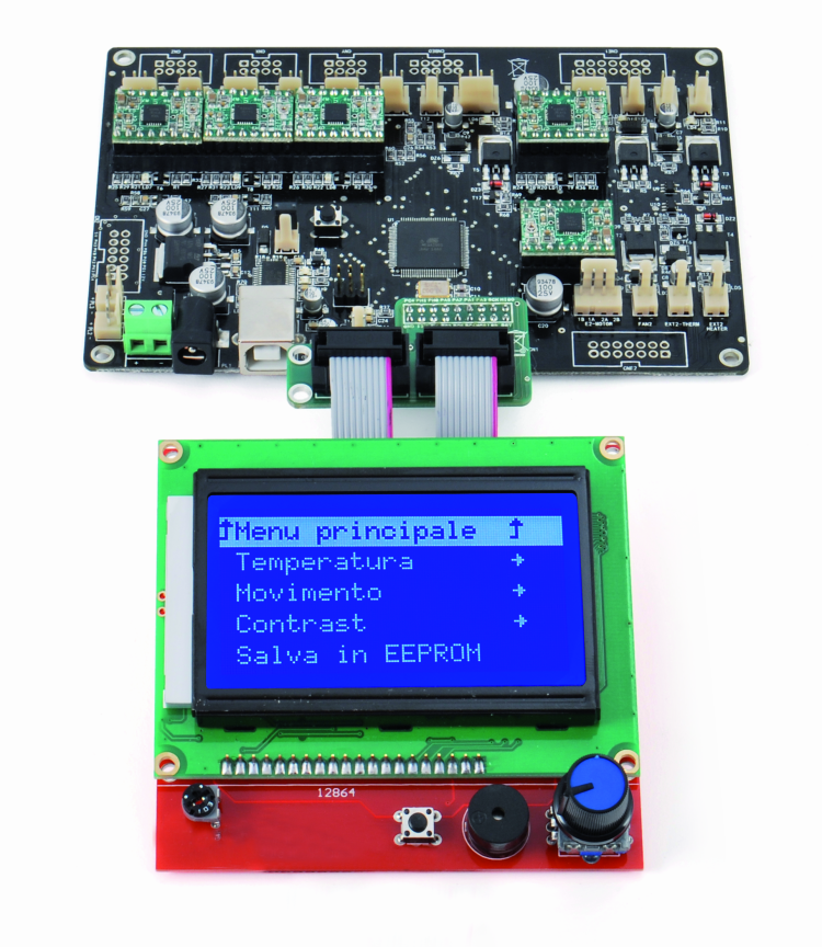
Full Graphic Smart Controller display for 3Drag 3Dprinter

Let’s substitute our 3D printer’s command panel with a dot-matrix that enables the display of graphics, function icons and animations.
We would like to remind you that our 3Drag printer (that prints plastic items of the size of 200x200x200 mm) may be supplied with a command panel, so to locally manage the printing processes without the need for a computer; this is very handy when you have – as an example – to bring your gear to a customer, so to print him a demo, and also when you need to print items that require several hours, since in this way it is possible to save the electric power that otherwise would be drawn by the computer, in order to drive the printer for all that time. This is possible, because of the fact that in the panel a SD-Card is included, from which the print file is loaded.
In these pages we will present a new panel, supplied with a dot-matrix graphic display. This enables both the obtaining of animations and the visualization of icons during the print execution, and the visualization of more menu entries and files contained in the SD Card, thanks to the increased size.
The panel requires the installation of a new firmware in the 3Drag’s controller board – and naturally an open source one, as it is for the whole 3Drag project – thus allowing the most “daring” ones to build customized animations, to be assigned to the execution of the print steps, or to be used to characterize the menu. But we will talk about this later; let’s take a look now at the new panel’s hardware.
Circuit diagram
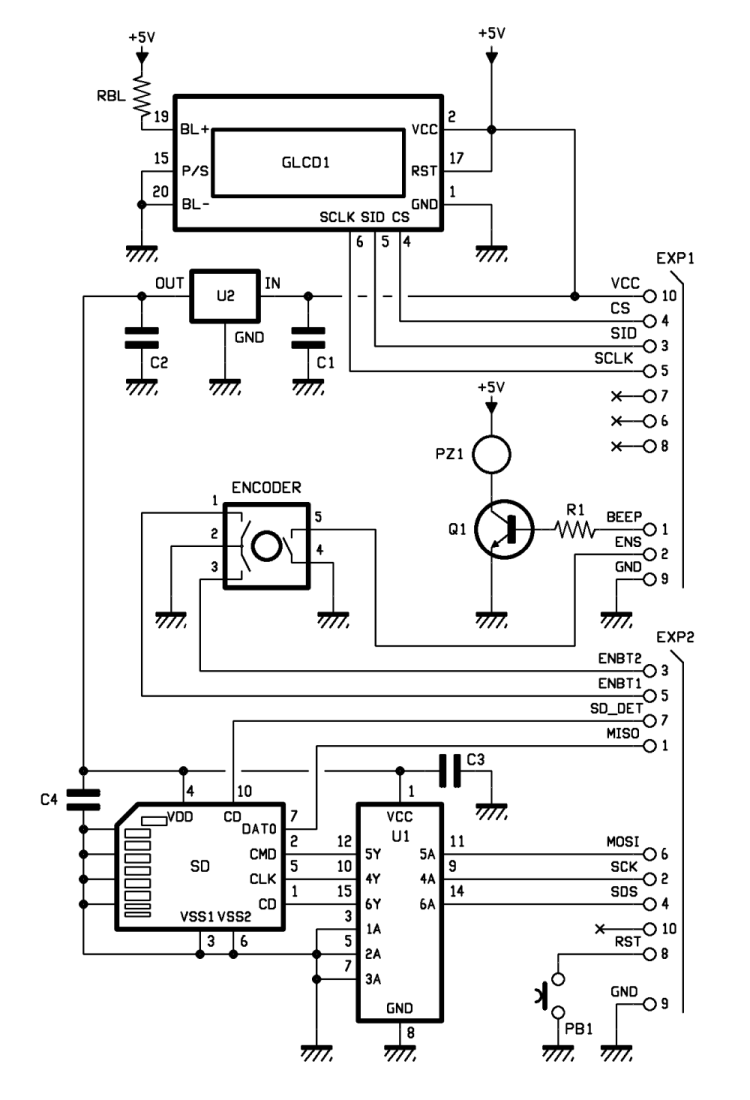
In this case, however, the display is a graphic LCD one, 128×64. The display board is connected to the 3Drag controller board’s expansion connector, so to bring the data lines to the LCD display, to the SPI bus in order to interface the SD card, to three digital inputs for the digital encoder and to the selection click, besides the reset line.
The panel is managed by means of the free Atmega2560 lines on the controller board; the 256 kbits possessed by Atmega’s Flash memory enable to load Marlin’s firmware, that this time is richer since it has been compiled with the SD and LCD options activated.
The display does not work in the parallel access mode (the alphanumeric one had RS, R/W, E, in addition to the four parallel bits: DB4, DB5, DB6, DB7) but in the serial access mode, that is based on a 3-wire SPI bus, having the SCLK (clock), the SID (bidirectional data line) and the CS (Chip Select).
The retroillumination is a fixed light one, and is powered by means of the RBL resistor, that brings the current to the BL+ positive; the LED retroilluminator’s negative is connected to the ground (BL-). The display’s reset line has not been used and has been deactivated, by setting it to a fixed logical 1. The P/S line, that is found in the KXM12864M-3 display version only, determines if the communication interface with the controller (in our case, the 3Drag board) has to be in parallel or serial mode; in our case it has been connected fixedly to the ground, thus the display will operate in the serial bus mode, while if it had been connected to the +5V, the viewer would have been commanded just like all the parallel LCDs. In the serial mode, the RS (4), R/W (5) and E (6) lines become, respectively, CS, SID and SCLK.
In order to manage the graphic display, a dedicated library has been written, so to generate the data accordingly to the serial protocol needed for the purpose.
The graphic LCD panel is connected to the controller board by means of the EXP1 connector, from which the 5V Vcc power comes as well: the latter is reduced by the U2 integrated regulator that stabilizes it at 3.3 volts, for the purpose of the usage by the SD-Card; in fact this memory card is powered between 2.7 ad 3.6 volts and does not tolerate 5 volts, which is why in the circuit diagram you may see it as interfaced to the EXP2 connector (from which a second flat-cable begins: it reaches the 3Drag controller board) by means of a level shifter from 3.3V to TTL(0/5V). The voltage regulator is a MCP1702-3302E, that enables the adjustment of the power supply for the memory board, from 5 to 3.3V.
The level shifter is a 74HC4050, that is internally composed of six non-inverting buffers, that accept voltage levels up to 15V on the inputs – that are marked with A – for the logical level 1, while this level on the outputs – that are marked with Y – is limited to the integrated circuit’s power voltage that, in our case, comes from the 3.3V regulator. The logical signal to command the buzzer comes from the EXP1 connector, that polarizes the NPN Q1 transistor at the base, thus causing PZ1 to sound when on the BEEP line there is the logical 1; anyway this function is not managed by the 3Drag controller. Even the ENS line, that is used by the controller board in order to read the encoder’s click, passes through EXP1.
On the other hand, the SD Card is connected – by means of the U1 level shifter – to the EXP2 connector, from which it interfaces the pins (for the purpose of the SPI dialog) that are found on the controller board, in parallel to the lines for the in-circuit programming of the bootloader and the firmware.
The lines that are used by the SD Card are the CMD, the CLK and the CD, that are respectively “adapted” on the MOSI (Master Output Slave Input). The data line coming from the controller board’s microcontroller, the SCK (the serial communication clock) and the SDS (the chip select); the other SD Card’s control lines are outputs and are not translated since the 3Drag controller board’s microcontroller lines are 5V-tolerant, therefore they read the 3.3 volts just the same as a logical 1. It is a DAT0, operating as a MISO (Master Input Slave Output), that is to say, as a data channel from the card to the microcontroller, and a SD_DET, that is used in order to detect the SD Card being inserted in the reader. The EXP2 lines’ set is completed by the ENBT1 and the ENBT2, that supply the encoder’s pulses to the controller board in a direction and in the other one, thus allowing both the step count and the detection of the rotation direction.
As required by the library related to the usage of the SD Cards and of the SPI bus, in addition to the native pins of the ATmega 2560’s SPI port, a pin must be destined to the device’s CS and in our case the PA3 has been used, and it was initialized as an output. The component that has been indicated as Encoder is a device that enables us to scroll the pointer in two directions, “up” and “down”; the two switches inside it are connected to the pins 1, 2 and 3, and generate pulses with the rising edges that are out of sync, so to allow the microcontroller to understand if the rotation is a clockwise or counterclockwise one.
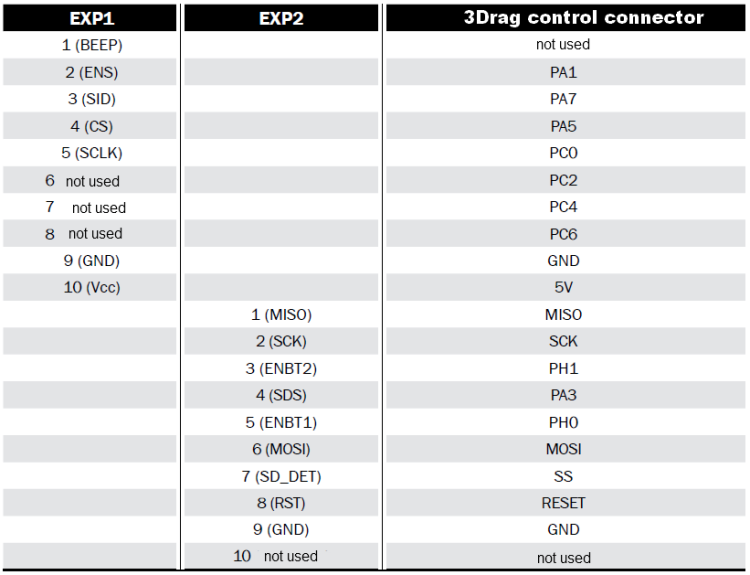
The closing of the contact between the pins 4 and 5, that is generated by a pressure on the post, is detected by the software, and interpreted as a selection command; in practice, this component behaves as an interaction wheel of the turn-and-click system, a very effective one for scrolling menus that are composed by lists on more than one level. The microcontroller’s lines that are used in order to read the encoder are highlighted in Table .
A reset button can also be found on the panel: it is connected to the microcontroller’s reset pin, and repeated on the ISP’s six-pin connector and needed in the programming phase; the button is needed as well, during the print, in order to “unblock” the printer in the case of crashes, errors or other situations in which it would be otherwise impossible to retake control of the situation. The flexibility of the Marlin firmware, that has been installed on the controller board, allows anyway to remap all the pins in the appropriate way, by modifying the PINS.H file; for your convenience, the file for the controller board – with the definition of the managed pins – is available on our website.
The hardware is completed by the C1 capacitor (used in order to filter the power coming from the controller, that might gather interferences when passing on a flat cable) by C2, C3, C4 (used in order to filter the 3.3V supplied by U2), by the RBL resistor (that limits the current absorbed by the display’s LED retroillumination).
The SD Card is read by means of the SD1 printed circuit board; the SD format (and not the microSD) has been chosen since it is sturdier and more suitable for a usage characterized by repeated insertions and extractions. Moreover it is more versatile, since you may even mount a microSD, by means of the specific adapter.

Assembly
As regards the installation: after having mechanically placed the panel – with the printer turned off – you may connect the cable from both sides, seeing that there is correspondence among pins (please refer yourself to the coloured side of the cable).
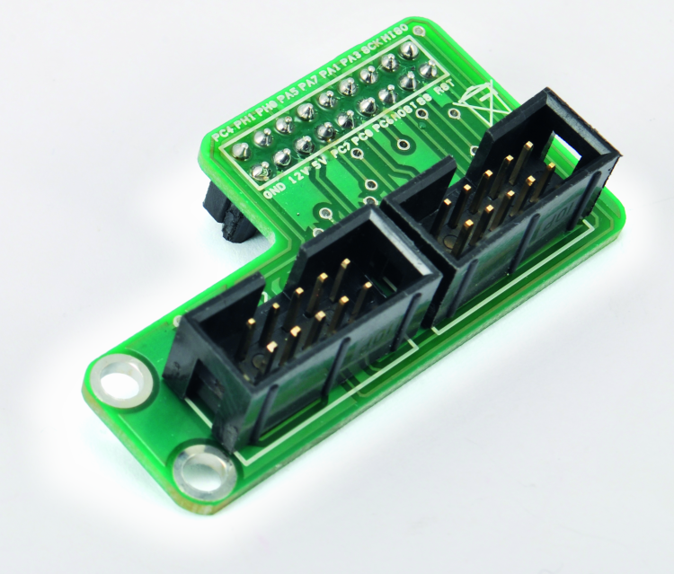
Since there are two connectors in the display, while in the 3Drag controller there is only one, an adapter has been created (it can be seen on the picture in the opposite page), on a side it has the male connectors for a flat-cable, and on the other it has the female connector to be inserted in the controller board’s male; as for this adapter (that you may create by assembling the connectors on a stripboard), you will find in Table the correspondence between the EXP1 and the EXP2 of the display module and of the controller’s connector.
The adapter board is compatible with the electronics of our 3Drag, as per versions V1.1 and V 1.2.
The new firmware
In order to manage this new panel, a new firmware has been prepared: it takes advantage of some functions of the Marlin firmware (found in the 3Drag controller board’s ATmega2560), so to manage the functions for independent printing.
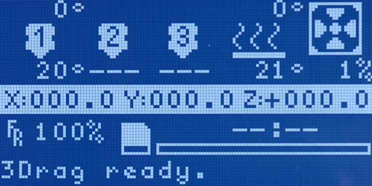
In the firmware, there are some modules that are dedicated both to the LCDs’ piloting and to the SD memory card’s management. While printing files found on the SD Card, but with a printer connected to a PC – thanks to a series of messages and commands sent and received by the firmware via serial communication to the host computer – it is possible to control the printing process to such a degree of completeness that all the options offered by the best printing packages for a PC are available. Without a PC, on the other hand, it is possible to have – via display and encoder – a control concerning real time temperature, acceleration, speed, flow rate, preheating, motors’ block and release, movement and everything regarding the plan (or the extruder) positioning control. With the activation of the part related to the SD Card, the firmware adds commands and functions, so to enable the file management even via computer, and without having to extract the card (which would be needed in order to add or modify the files that will then have to be printed).
With the onboard memory, the firmware is then capable of queueing various jobs, always by communicating with the printing software by means of specific messages. As for the SD card management, the major printing clients (Repertier-Host, Cura Engine) provide a dedicated section, by means of which it is possible to interact specifically with the printer that, when having a SD card inserted, has enough local memory available: it is needed in order to “buffer” one or more files.
The panel shows, if a SD Card is needed, all the GCODE files that it is possible to print, and hides instead the system files, or those that cannot be printed. The files that are already there cannot be deleted or sent for the printing, while from the panel it is possible to create a folder or to load a file that will be printed later.
In order to proceed with the firmware update concerning the graphical panel management, it is sufficient to follow this simple procedure:
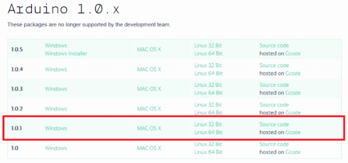
The code has been written for Arduino IDE version 1.0.1, therefore if you want to manually operate on the firmware you will have to:
- Access the arduino website, and then download the version 1.0.1 from the “Download” section;
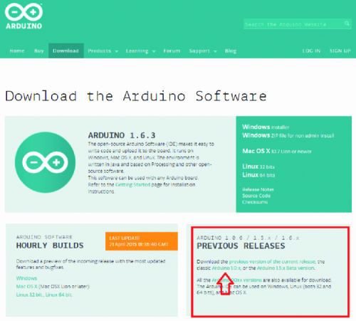
- Download the version 1.0.1 for the operating system being used;
- Download the version 1.0.1 for the operating system being used;
- Once the download has been completed, please install the IDE or decompress the compressed folder, so to open the development environment;
- Once the IDE has been installed, given that we want to use the graphical display, we have to recover the display management library and Marlin firmware’s source code, that will have to be modified in order to be then loaded inside of the 3D printer’s control board; in our case we will have to download the dedicated library for Arduino, by accessing the web page and by clicking on Download;
- From the following page, please download the library file;
- Once the library has been downloaded, please decompress the content and copy the “U8glib” folder inside the “libraries” folder, that can be found where Arduino’s IDE has been installed;
- Please load the firmware by pressing the Upload button on the IDE, and wait for the indication that the download has been completed: it can be found on the environment development’s status bar.


Controller card for 3D printer dual extruder
Once the loading has been completed, the board is ready for the usage. Please remember to regulate the display’s contrast, by means of the trimmer found on the display itself (on the back), otherwise the images and the texts may not appear sufficiently clear, or may not be visible at all.
From Openstore
3D Printer Full Graphic Smart Controller with 3Drag adapter

Related Posts


-
 Arduino ISP (In System Programming) and stand-alone circuits
We use an Arduino to program other ATmega without...
- Posted 12 years ago
-

-

-
 GSM GPS shield for Arduino
Shield for Arduino designed and based on the module...
- Posted 12 years ago
-
 Small Breakout for SIM900 GSM Module
Some post ago we presented a PCB to mount...
- Posted 13 years ago
-
 ESP32 Low Power Module
ESP32 Low Power Module, based on Espressif’s SoC capable...
- Posted 1 week ago
-

-
 Application For Maker Faire Rome 2024: Deadline June 20th
Learn More About the Ideas, Makers + Projects at...
- Posted 2 weeks ago
-
 GSM/4G Remote Control with DTMF Commands
Two-way remote control system, based on the GSM/4G A7682E...
- Posted 4 weeks ago
-
 Join Maker Faire Rome 2024: Innovation Unleashed at Gazometro Ostiense | Calls Now Open!
All Calls Now Open for Maker Faire Rome 2024...
- Posted 1 month ago