- Building a 3D Digital Clock with ArduinoPosted 4 months ago
- Creating a controller for Minecraft with realistic body movements using ArduinoPosted 5 months ago
- Snowflake with ArduinoPosted 5 months ago
- Holographic Christmas TreePosted 6 months ago
- Segstick: Build Your Own Self-Balancing Vehicle in Just 2 Days with ArduinoPosted 6 months ago
- ZSWatch: An Open-Source Smartwatch Project Based on the Zephyr Operating SystemPosted 7 months ago
- What is IoT and which devices to usePosted 7 months ago
- Maker Faire Rome Unveils Thrilling “Padel Smash Future” Pavilion for Sports EnthusiastsPosted 8 months ago
- Make your curtains smartPosted 8 months ago
- Configuring an ESP8266 for Battery PowerPosted 8 months ago
Back To The Future – Build your Flux capacitor
We will show here a modern take on the equipment that enabled time travel in Back to the Future.
Those who have a few “decades” of ageing on their shoulders should know Back to the Future (but the younger ones as well, since they could know and see it thanks to YouTube streaming), the famous movie that then became a saga… in three installments. The great appeal of the movie – directed by Robert Zemeckis, and with no less than Steven Spielberg as an executive producer – lies in the bizarre and futuristic adventure of a teenager, Marty McFly (played by Michael J. Fox), that managed – with the help of an eccentric-looking scientist – a certain Emmett L. “Doc” Brown (whose real name is Christopher Lloyd) – to travel in the future (and in the past as well) by means of a time machine. The messy gear, the car on which Marty travelled, was created by the Doc and became a cult. It was the DeLorean DMC-12, chosen by the professor, who was sure that: “if you’re going to build a time machine into a car, why not do it with some style?” This car, a new time machine, had to receive an electric power of 1,21 Gigawatt in order to be able to make the jump: an enormous amount that was then used by the “flux capacitor”, placed behind the DeLorean’s seats. Initially, the flux capacitor was powered by some plutonium, while in the follow-up movies it was simply needed to introduce some garbage in the Mr. Fusion conversion device, in order to start the nuclear fusion and to develop the power needed.
In the movie, after the time circuits were activated, and the destination date and time were set, McFly had to start the engine and accelerate up to 88 miles per hour (141,6 km/h), so that the flux capacitor could be activated. Once the time jump was performed, the DeLorean was to be found in the same physical position on Earth of the time of the departure.
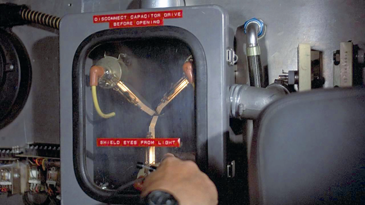
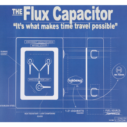
The “Back to the Future” fans will remember that the panel showing the flux capacitor’s state was composed of a three-pointed star, with the points being lamps, to which three cables with the typical rubber pipe insulation were applied. They will also remember that in the first installment, the data chosen for the experimental journey in the future – by the uncertain destiny of the two main characters – was the 21st October 2015; yes, right: it’s a day of this current month.
Back to the future encouraged the curiosity and the imagination of many fans, so that for this date many commemorative events have been organized, some of them even promoting some suggestive comparisons with what the movie proposed (as regards the future destination scenario for Marty McFly and Doc). As an example, the video communication (if you want, it can be rendered today with Skype) and the flying cars (that, by the way, were speculated in movies such as Minority Report as well) that, unfortunately for the screenwriters and fortunately for us, still do not exist…
But after all, during the ‘80s of the past century (as well as even before), the progress led the most optimistic directors and screenwriters to dream an evolution that turned out to be much faster than the one that the laws of Physics could and have imposed; on the other hand Back to the Future was not the only futuristic diversion, since from the conquest of the Moon (and of the Space more in general) led the cinema and the television to propose series such as Space: 1999 (in which it was theorised that the Moon had become the depot for radioactive wastes and that was populated by 300 inhabitants of the futuristic Space Base Alpha, that it was pulled out from the earth orbit and projected in an infinite journey in the Space) and Star Trek or Star Wars.
The fact that the first time travel jump in Back to the Future has the 21st October 2015 as a destination, made us surrender to the enthusiasm that is currently overwhelming the fans of the trilogy, and that stimulated the Maker part of us, a part that everyone has inside. It is a short step from the passion to the idea, and it was as fast to render it in practice: a few hours in the workshop and the project proposed in these pages was born. It is a modern take on the flux capacitor device, and with it we want as well to pay homage to the great dream that Robert Zemeckis shared with the “Back to the Future” fans, and to the passion raised by a time machine version that was more realistic than the ones proposed in other movies, that were certainly unlikely. This was surely because in those years, electronics made us believe what in the end happened up to a certain measure, that is to say that it was the technology to create what once was impossible.
And in a certain way the appeal of electronics is somehow this one, since differently from other disciplines, and being it something that cannot be seen and cannot be immediately explained, we humans are inclined to entrust our dreams and our hopes to it (and differently from mechanics, for example, that is more immediate and can be seen, and thus lends itself less to make us imagine space age creations made by means of it).
Our project
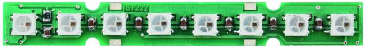
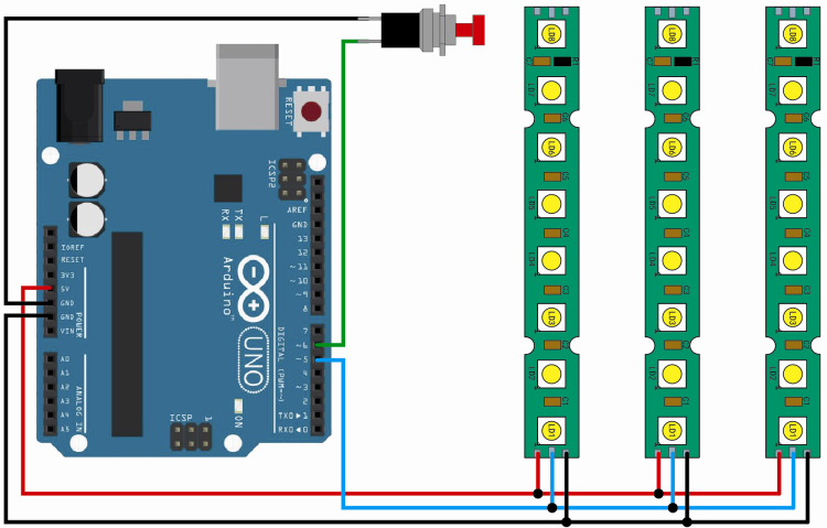
In order to simulate the flux capacitor device that once casted the DeLorean in time, we made use of the now ubiquitous Arduino Uno that, with a dedicated sketch loaded (and this time without need for any shield) drives three strips, each one with 8 Neopixel LEDs. The strips are managed in parallel, by a single Arduino line, that in our case can be easily modified at leisure by specifying it in the sketch; the communication is a one-directional one and manages a group of LEDs, that in our case are 24.
The connections of the set are illustrated in these pages in the wiring diagram.
Before continuing, it is appropriate to spend a few words about the Neopixel technology, since it enables the creation of “smart” RGB LEDs with a controller onboard. They can be easily integrated in the Arduino environment, thanks to proprietary libraries that Adafruit (www.adafruit.com) has made freely available. A distinctive trait of the Neopixel LEDs is that they can be connected in cascade, so that the data line from one may pass to the following one. The price to pay, however, is that a beyond a certain number of LEDs the management speed must be considerably reduced; because of that, if in need to create matrices to show some fast graphics, one must use many lines with few LEDs for each one.
But this kind of limitation does not concern our project.
Each RGB LED can be individually managed by means of a dedicated command, included in the serial string and can produce up to 256 tones of its own colour, thus determining a total of 16.777.216 colour combinations. In practice, Neopixel is a solution that considers the integration of a driver and of its relative RGB LED in a SMD case, thus allowing the direct command, LED by LED.
The data channel that is used for the communication with the Neopixel LEDs, and thus with the strips, is similar to those of the oneWire type. The power source considered for the Neopixel LEDs is a 5 volts one; the communication takes place at a maximum of 800 kbps.
For each LED strip it is possible to set the refresh frequency at leisure, in order to make certain tricks of the light imperceptible. In our case, the scan frequency of the LEDs is 400 Hz, for each strip.
Further strips may be connected in cascade or in parallel, in order to create various effects, but in this case such a configuration does not concern us. Keep in mind, however, that the more strips are connected to a single data channel, the more the refresh frequency will be limited (it being understood the maximum data-rate allowed). Briefly, the refresh frequency and thus the turning on/off speed for the single LEDs is inversely proportional to the number of LEDs to manage.
The Neopixel system’s command protocol considers the sending of three bytes in a 24 bit string, each one of them containing the lighting state for each base colour (the eight bits of the green first, then those of the red, and finally those of the green). Let’s analyze, therefore, the strip’s circuit diagram. The extreme simplicity of the creation is obvious: each smart LED is connected in cascade, given that the data line entering the terminal DI exits from DO, that repeats its data. The power source is a 5 volt one (the strip’s voltage), that can be drawn from Arduino’s 5V contact, given that the current absorption for each strip does not reach 200 mA, and that the Neopixel three coloured LEDs are alternatively lighted. The reference ground for the power source and data (it is the only one, depending on the strip’s G contact) is always Arduino’s one and goes to the GND of this last board. The many capacitors placed on the power source are needed to filter the impulses created on the tracks as an effect of the absorption by the LEDs, when they are lighted. This is necessary, since the pulsation of the diodes’ power supply’s is at a high frequency, and otherwise the noises (that in the end are voltage drops, even if feeble ones, that are concurrent with the lighting of the single LEDs) could interfere with the proper operation of Arduino.

Let’s get back to Arduino, now, and see that beyond the the board and the three strips in parallel we connected a button, that we need in order to be able to choose among the tricks of the light considered by the sketch. The button is normally an open one and is connected to Arduino’s pin 6 and to the ground (the pull-up resistor of the corresponding Atmega’s pin is enabled by the software, so to save us an external resistor and to simplify the wiring). Everything is powered via USB, thus via a PC, but it is also possible to power Arduino by means of a dedicated plug; in this case it is advised to use a power supply with an output voltage not greater than 7,5V, in order to not “stress” too much Arduino’s internal regulator. Once the powering has been supplied, Arduino loads the sketch and periodically checks the button’s state; at the same time it starts the default trick of the light, that considers the LEDs lighted with a white colour, and moving from the periphery to the center, all being synchronized while converging. Pressing the button once makes all the LEDs turn red in the same fashion, another pressure does the same with the green light LEDs and a further intervention on the button repeats the game with the blue lighted LEDs. Pressing the button further will produce more light games, for a maximum of 10 as a total. Among these, you will find a trick we created, that perfectly reproduces the effect of the movie’s flux capacitor. Once the tenth one has been reached, it will restart from the default one at the start.
Practical Realization
Since we wanted to create something that would replicate the panel of the movie’s Flux Capacitor in the most faithful way possible, our project had to have, in addition to the electronic parts, mechanical parts that would look as much as possible like the original ones. Since the switchboard in the movie was the typical one, in metal with a glass window and rubber gasket, we created therefore a “fake” one, made with a grey cardboard box, painted grey, in the place of the switchboard. Then we applied a thick acetate leaf with a fake rubber gasket, 3D printed in black PLA, by means of our 3Drag printer.
You could make a plastic box instead, but still you would have to paint it grey.
The strips have been arranged in the shape of a three-pointed star, and applied to a false bottom made in corrugated cardboard and painted black, while Arduino has been assembled behind it (between the false bottom and the bottom), secured with distance rings glued to the bottom of the box by means of hot glue.
To make the emitted light more uniform, and more similar to the tubular discharge lamps that were used in Back to the Future, we inserted each strip in a transparent plastic sheath, obtained from a part of a transparent pipe (of those used for watering), having a diameter a bit greater than the strip’s width. You could use a transparent and smooth pipe, as well as a translucent one, or one having a machined surface.
The strips’ connection wires come out from a hole in the center of the star (at least the real ones, that is to say, the three ones that go to Arduino). They can be obtained with pieces of a twin lead having three wires, that then have to be connected in parallel with three points (or Arduino’s jumpers), inserted in Arduino’s expansion connectors, in the position that is indicated by the wiring diagram.
The wires that are applied to the other end of each strip are purely for scenery purposes (they are totally fictitious) and simulate the wires of the discharge lamps’ ends that are found in the panel, as seen in the movie. Each one of them can be secured by means of (red) pipe insulators, coming from the spark plugs of a petrol engine, applied on metal screws that are tightened on round 40mm insulators, that are 3D printed and glued to the black cardboard. The fake wires, that in the original machine in the movie would bring the high voltage, can be obtained by painting transparent rubber pipes (with a diameter of 6÷8 mm) in yellow: you will take care to introduce them in the cardboard.

The sketch
To obtain the tricks of the light, the sketch that we make available on our Internet website www.elettronicain.it (along with the other project files) has to be loaded in Arduino, by means of the dedicated IDE or via a USB connection to the computer. The sketch makes use of the Neopixel.h Adafruit library, that is included since the beginning (before pins and variables are defined) by means of the following line:
#include <Adafruit_NeoPixel.h>
Soon after that a pin is assigned: it is used for the connection of the button used to select the tricks of the light (the sixth one, in this case), that is achieved via the following instruction:
#define BUTTON_PIN 6
The communication with the LED strips is assigned to the Digital I/O 5 (D5) pin via the following instruction:
#define PIXEL_PIN 5
Thus, if you wish to change Arduino’s line (for example if you mean to use Digital I/O 5 for other purposes), please modify (by editing the sketch via Arduino’s IDE) this line, by writing the desired pin number in the place of the 5, then save the sketch and load it again in Arduino.
Finally, within the sketch the number of LEDs to be driven for each strip is defined, and it amounts to 8:
#define PIXEL_COUNT 8
At this stage the firmware can be started, it can manage both the reading of the button in loop, and the visualization on the LED strips (obtained by means of a switch/case structure and the usage of the Adafruit library).
From the celluloid to the reality
As it often happens when one dares to forecast something about the world of tomorrow in a literary narrative or a movie, even in Back to the Future the director and the screenwriter created some scenes that proposed their vision of the time to come, and of the innovative things that would have come with it. But, in the same way as in Space: 1999 (the English serie), where it was theorized that already in 1996 we would have had a lunar base inhabited by humans, while today we barely have the ISS wandering in the Space around the Earth, even in Back to the Future we saw things that amazed us, and in the reality they are “yet to come”.
It is evocative to try to make a list of what came true and what didn’t. Surely there are things today that the movie had forecasted and that we find today in the real world. The first one is video communication, that is enabled by video chat services, such as Skype; the second one is given by the security systems accessing biometric parameters, that is to say identification technologies that are based on the fingerprint recognition, on the face shape and iris recognition, etc. The third one is given by flat screens (LCD, OLED, etc.) and multivision or, if you want, PIP (Picture in Picture) technology and the same multiple view technology used in video surveillance.
The fourth invention is given by flexible displays, for example like the panoramic ones of the most modern curved screen TVs and the OLED ones of smartphones such as Samsung Galaxy.
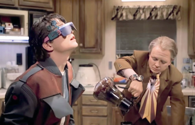
And how could we forget to talk about the PC Tablets, a fifth prediction from Back to the Future? To them we may add the video glasses, an almost oniric vision of Google Glass.
The 3D holograms, that were by the way proposed by other movies (for example, Total Recall, starring Arnold Schwarzenegger…) are now a possibility, thanks to the holographic laser. The eight innovation is given by the video games that, instead of a joystick, use a gesture recognition system: e.g., we are talking about the Microsoft Kinect, the Wii, and other systems having wearable sensors.
A ninth prediction that came true is the Slamball, a team sport inspired by basketball. They are distinguished since on a Slamball field there are four trampolines, placed under each basket, that enable the players to amplify their jumps and make some slam dunks. In other words, it is a sort of acrobatic basketball game…
At the tenth place we find high-tech clothing, of which a forerunner is the one worn by McFly: special fibers, sensors and actuators that enable it to adapt to the body and communicate the condition of the person wearing them, in the perspective of wearable electronics and IoT.

The Robotic dustbins that chase the Doc in one of the most funny scenes in the movie can be compared to the street cleaning robots, that have been introduced since a while in various research centres (for example, by the Sant’Anna School in Pisa).
A twelfth prediction that came true concerns the camera drones: in Back to the Future there are small planes that chase the news, shoot the facts and broadcast them (in the movie they also shoot the trial at the court). Nowadays drones are very much in use, and amateur multicopters, supplied with a video camera for aerial photography, are very popular.
The disappearance of the LaserDisc (a forerunner, albeit bigger, of the dvd format) was announced to Marty McFly: they were used in the video juke boxes and were available for sale until 1998.
In 2015, Marty and Jennifer McFly had a house in which everything was connected and could be commanded; this is something that came true, thanks to the always growing appeal of home automation, smart technologies and IoT. A similar situation can be made for the Homechat system, that was presented by LG during the last CES in Las Vegas: it enables the possibility to exchange messages with the household appliances, as if they were a person.

Finally, the hoverboard: the flying skateboard in Back to the Future, akin to a hovercraft, could become available for sale for real, by the end of this year. So it was promised by the company Haltek Industries.

Related Posts


One Comment
Leave a Reply
-
 Arduino ISP (In System Programming) and stand-alone circuits
We use an Arduino to program other ATmega without...
- Posted 12 years ago
-

-

-
 GSM GPS shield for Arduino
Shield for Arduino designed and based on the module...
- Posted 12 years ago
-
 Small Breakout for SIM900 GSM Module
Some post ago we presented a PCB to mount...
- Posted 13 years ago
-
 Join Maker Faire Rome 2024: Innovation Unleashed at Gazometro Ostiense | Calls Now Open!
All Calls Now Open for Maker Faire Rome 2024...
- Posted 3 weeks ago
-
 Building a 3D Digital Clock with Arduino
Project to create a digital clock consisting...
- Posted 4 months ago
-
 Acoustic amplifier – in DIY Kit
This kit creates a microphone amplifier with an output...
- Posted 5 months ago
-
 Creating a controller for Minecraft with realistic body movements using Arduino
Project of a controller that maps body movements...
- Posted 5 months ago
-

Pingback: Build your own LED powered light Saber | Open Electronics