
In this second “episode” (here the first one), we will go deeply inside Fishino features, showing the main libraries and code sketches.
In the last post we have presented the Fishino UNO board, compatible with Arduino UNO but offering WiFi connectivity, a microSD slot and a built-in RTC.
In this second post we begin describing the available software libraries, explaining the main functions with some simple examples of use.
As anticipated, both the board firmware and the software libraries are constantly under development, so we recommend keeping them constantly upgraded.
Libraries
To take advantage of all the Fishino features we must obviously have a set of software libraries to handle all the additional components.
If the SD card and the Real Time Clock (RTC) functions are already available in the corresponding Arduino libraries, the ESP12WiFi module is not present in the suite, that’s why we had to develop a proprietary library.
We will start then from the Wi-Fi features, but later we’ll provide details on those already available in the IDE too.
The supplied libraries, freely downloadable from our site are:
- ‘Fishino’
- ‘FishinoWebServer’
- ‘Flash’
The last library, Flash, is freely available on internet but we have inserted it in the downloadable package anyway, since it is a necessary component for the functioning of the previous two.

‘Fishino’ Library
Let’s start with the description of the library (which can be downloaded from fishino website) that handles the Fishino WiFi module lower and middle level.
This defines three classes:
- FishinoClassand its global variable “Fishino”
- FishinoClient
- FishinoServer
The project is constantly evolving, well supported by a very active community on Facebook;
Thanks to this community, we will add in a second phase the FishinoUdp, FishinoAnalog, FishinoDigital and FishinoSerial libraries to manage respectively the UDP network protocol, the analog inputs, the digital I/O and the additional hardware serial port built on the WiFi module.
Let’s begin with the FishinoClass description (single instance in the global variable Fishino), explaining with practical examples the various functions.
With bool Fishino.reset () we can initialize the WiFi module by sending a software reset. Required at the very beginning of your sketch to ensure a successful module boot. Returns TRUE if the module has been properly initialized, FALSE otherwise.
The reset function also checks the firmware version. If outdated, sends an error message over the serial port and the program is stopped. Listing 1 shows an example of proper initialization routine in the Setup function. Apart from the usual serial port initialization (to be done at the beginning of setup), you see:
- initializing the SPI
- Fishino.reset ()to init the module
Listing1
void setup()
{
Serial.begin(115200);
while (!Serial);

SPI.begin();
SPI.setClockDivider(SPI_CLOCK_DIV2);
if(Fishino.reset())
Serial.println(“Fishino WiFi RESET OK”);
else
{
Serial.println(“Fishino RESET FAILED”);
while(true)
;
}
Serial.println(“Fishino WiFi web server”);
<span style="font-weight: 400;"> </span>
The first procedure has been intentionally left “manual”, not included in a function, to have more flexibility in order to change the communication speed, if there are other shields using the same interface. In this example, we set it to the maximum available speed.
The section containing the Fishino.reset () call, initializes the module and sends a message over the serial interface if successful. Otherwise, in case of problems, reports the error and blocks the sketch.
Warning, the WiFi module DON’T start without this command.
bool Fishino.setMode (uint8_t mode) and uint8_t Fishino.getMode (void) functions set (or read) the module working modes (Listing 2), that can be as follows:
- STATION_MODE It requires a Wi-Fi router to connect to. It is the normal working mode.
- SOFTAP_MODE creates an access point you can connect to. Useful in the absence of an existing network infrastructure.
- STATIONAP_MODE Dual mode, the module works either as an access point or connecting to an existing router.
Listing2
Fishino.setMode(STATION_MODE);
To connect to the access point / router you must use the bool Fishino.begin (SSID, PASSWORD) function. Obviously, SSID is the network name and PASSWORD, if not needed, can be left blank.
To check whether Fishino is properly connected, the command is uin8_t Fishino.status (). The function returns TRUE if the connection is successful, FALSE otherwise. In the code snippet in Listing 3, the connection function is invoked in an endless loop until it is successful.
Listing3
while(true)
{
if(Fishino.begin(“MY_SSID”,“MY_PASSWORD”)) {
Serial.println(“Connected to MIO_SSID”);
break;
}
else {
Serial.println(“Failed connecting to MIO_SSID”);
Serial.println(“Retrying.....”);
}
}
This type of connection procedure (executed in the Setup function) is suitable for a fixed application since it is a high resource consuming, of course. If using Fishino in mobility, you can move the connection function in the loop () and invoke it on a schedule while doing other activities.
This way you can, for example, collect data from a sensor, store them on the SD card and when a working connection is detected, send them to a remote computer (Listing 4). In this example (intentionally abbreviated), in setup () it is read the current time and stored in the connectTime variable; later in the loop () we check the elapsed time (millis () – connectTime) and every 10 seconds run a connection test. If not connected you try to connect to the server and, if successful run a function (to be defined) that saves on the network the previously read data.
Listing4
uint32_t connecTime;
void setup()
{
..............
connectTime = millis();
}
void loop()
{
if(millis() - connectTime > 10000) {
connectTime = millis();
uint8_t stat = Fishino.status();
if(stat != STATION_GOT_IP) {
if(Fishino.begin(“MIO_SSID”, “MIA_PASSWORD”))
stat = STATION_GOT_IP;
}
if(stat == STATION_GOT_IP) {
salvaDatiSulServer();
}
leggiSensoriEMemorizza();
}
The loop then continues through another function (also to be defined) that reads from a sensor and stores the data locally, i.e. on the SD card.
With this sketch is thus possible to make a simple data logger which not only reads and stores data on the SD card, but which, in the presence of a network connection, is able to save them in a completely automatic manner at predefined time intervals.
To configure a static IP and DNS servers, Gateway, and the subnet on the local network use these functions:
bool Fishino.config (IPAddress local_ip)
bool Fishino.config (IPAddress local_ip, IPAddress DNS_SERVER)
bool Fishino.config (IPAddress local_ip, IPAddress DNS_SERVER, IPAddress gateway)
bool Fishino.config (IPAddress local_ip, IPAddress DNS_SERVER, IPAddress gateway, IPAddress subnet)
In practice, the first sets a static IP, if necessary. In Listing 5 we see how you can set a static IP (192.168.1.251). If you don’t use this function, the IP address will be automatically set by the DHCP.
Listing5
Fishino.config(IPAddress(192, 168, 1, 251));
We could also disconnect the network. The command to do this is bool Fishino.disconnect (void).
Here are also some functions used to control the connection parameters:
- To read the WiFi module MAC: const uint8_t* Fishino.macAddress (void)
- To get the IP acquired by the WiFi module (useful if you set a dynamic IP) invoke IPAddress Fishino.localIP () as shown for example in Listing 6.
- To get the subnet mask and gateway IP address, you can call these functions:
- IPAddress Fishino.subnetMask ()
- IPAddress Fishino.gatewayIP ()
Listing6
Serial.print(“My IP: “);
Serial.println(Fishino.localIP());
The functions listed above were named in a similar way to the corresponding ones on Arduino Ethernet and WiFi library, in order to simplify the porting of existing code.
However the higher Fishino potential, and especially the possibility to operate also in access point mode without needing an existing infrastructure, requires us to study the new functions introduced by the station mode, including:
bool Fishino.setStaIP (IPAddress ip)
bool Fishino.setStaMAC (uint8_t const * mac)
bool Fishino.setStaGateway (IPAddress gw)
bool Fishino.setStaNetMask (IPAddress nm)
While the access point mode uses:
bool Fishino.setApIP (IPAddress ip)
bool Fishino.setApMAC (uint8_t const * mac)
bool Fishino.setApGateway (IPAddress gw)
bool Fishino.setApNetMask (IPAddress nm)
bool Fishino.setApIPInfo (IPAddress ip, IPAddress gateway, IPAddress netmask)
In particular, the last is used to set all Fishino IP parameters when configured as a WiFi router, with a single command (Listing 7).
Listing7
Fishino.setApIPInfo(
IPAddress(192, 168, 100, 1), // IP
IPAddress(192, 168, 100, 1), // Gateway
IPAddress(255, 255, 255, 0) // Netmask
);
We will see how to use them at the end of this article with a complete example. In order to read WiFi connection data and settings, such as the network SSID you are connected to, the router MAC (BSSID), the signal strength in dBm (RSSI) and the network security, you can use these functions :
const char * Fishino.SSID ()
const uint8_t* Fishino.BSSID ()
int32_t Fishino.RSSI ()
uint8_t Fishino.encryptionType ()
As shown for example in Listing 8.
Listing8
Serial.print(“Connected to: “);
Serial.println(Fishino.SSID());
There are also some functions used to list available WiFi networks with their characteristics:
uint8_t Fishino.scanNetworks ()
This will scan for available WiFi networks and returns the number of found networks.
After the scanNetworks, you can use the following functions, passing the network number as a parameter (total number is given by scanNetworks () – 1).
The function const char * Fishino.SSID (uint8_t networkItem) returns the SSID, i.e. the network name as shown in Listing 9. This example prints on the serial interface a list of the wireless networks found.
Listing9
uint8_t n = Fishino.scanNetworks();
if(n) {
Serial.print(“Find “);
Serial.print(n);
Serial.println(“ wifi:”);
for(int i = 0; i < n; i++) {
Serial.print(“Network #”);
Serial.print(i);
Serial.print(“ : “);
Serial.println(Fishino.SSID(i));
}
}
else
Serial.println(“No WiFi found”);
To know the type of network security, the right command is uint8_t Fishino.encryptionType (uint8_t networkItem).
We can also know the network signal strength with int32_t Fishino.RSSI (uint8_t networkItem).
FishinoClient and FishinoServer
These two classes are the Arduino Ethernet and Wi-Fi shields EthernetClient / WiFiClient and EthernetServer / WiFiServer equivalents, and their use is virtually identical.
For example, to send a request to a web page and print the response on serial interface check Listing 10.
Listing10
FishinoClient client;
if (client.connect(“www.google.com”, 80)) {
Serial.println(“connected to server”);
// esegue un request Http
client.println(“GET /search?q=arduino HTTP/1.1”);
client.println(“Host: www.google.com”);
client.println(“Connection: close”);
client.println();
do {
while (client.available()) {
char c = client.read();
Serial.write(c);
}
}
while(client.connected());
Serial.println(“Client disconnected”);
}
}
At the end of this post, we present a complete example that shows one of the most attractive features of Fishino, i.e. the possibility to create a network infrastructure without an external router, connecting to it for example with a mobile phone.
A similar application could be used, for example, to remotely monitor a number of outdoor sensors via a mobile phone, making so fully portable devices.
Another interesting application could be a WiFi remote control always via the phone web browser.
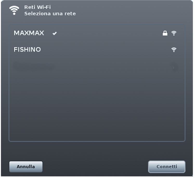
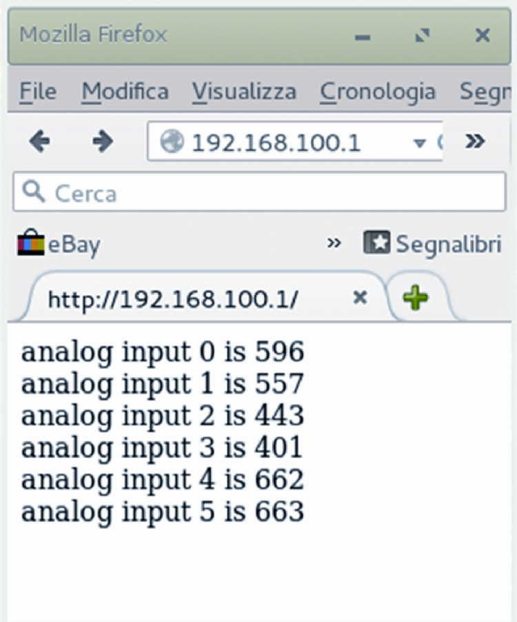
The example in Listing 11 creates a WiFi network named (SSID) ‘FISHINO’ without a password (open network) and starts a small server that provides on demand a reading of the six analog inputs present on Fishino. Once launched the sketch, you must select your wireless network (FISHINO) between available networks and connecting to 192.168.100.1 on the browser you get the result shown in figures.
The examples presented here are included, along with others, in the Fishino library.
Listing11
#include <Flash.h>
#include <FishinoUdp.h>
#include <FishinoSockBuf.h>
#include <Fishino.h>
#include <SPI.h>
#define My_SSID “FISHINO”
#define My_PASS “”
FishinoServer server(80);
void setup()
{
Serial.begin(115200);
while (!Serial);
SPI.begin();
SPI.setClockDivider(SPI_CLOCK_DIV2);
if(Fishino.reset())
Serial << F(“Fishino WiFi RESET OK\r\n”);
else
{
Serial << F(“Fishino RESET FAILED\r\n”);
while(true);
}
Serial << F(“Fishino WiFi AP web server\r\n”);
Fishino.setMode(SOFTAP_MODE);
Fishino.softApStopDHCPServer();
Fishino.setApIPInfo(
IPAddress(192, 168, 100, 1), // IP
IPAddress(192, 168, 100, 1), // gateway
IPAddress(255, 255, 255, 0) // netmask
);
Fishino.softApConfig(My_SSID, My_PASS, 1, false);
Fishino.softApStartDHCPServer();
server.begin();
}
void loop()
{
FishinoClient client = server.available();
if (client)
{
Serial.println(“new client”);
boolean currentLineIsBlank = true;
while (client.connected())
{
if (client.available())
{
char c = client.read();
Serial.write(c);
if (c == ‘\n’ && currentLineIsBlank)
{
client.println(“HTTP/1.1 200 OK”);
client.println(“Content-Type: text/html”);
client.println(“Connection: close”);
client.println(“Refresh: 5”);
client.println();
client.println(“<!DOCTYPE HTML>”);
client.println(“<html>”);
for (int analogChannel = 0; analogChannel < 6; analogChannel++)
{
int sensorReading = analogRead(analogChannel);
client.print(“analog input “);
client.print(analogChannel);
client.print(“ is “);
client.print(sensorReading);
client.println(“<br />”);
}
client.println(“</html>”);
break;
}
if (c == ‘\n’)
{
currentLineIsBlank = true;
}
else if (c != ‘\r’)
{
currentLineIsBlank = false;
}
}
}
delay(1);
client.stop();
Serial.println(“client disonnected”);
}
}
One last note on I / O already used by devices: those can’t be shared with other applications when these devices are used. The WiFi module uses the following pins: 7, 10, 11, 12 and 13. It is completely deactivated with a jumper between CH_PH ESP and ground pins.
The microSD card uses the following pins: 4, 11, 12 and 13 and requires the pin 7 set to digital output. To release those resources, simply do not put a memory card into the connector.
The RTC module communicates by using i2c pins SCL and SDA, coupled on Arduino UNO to analog ports A4 and A5.
From open store
