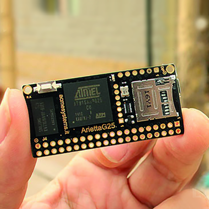
If you have “broken the ice” with GNU / Linux through Raspberry Pi already, here is a board that allows you to jump into the real professional world, with all the needed support and with totally “Open” instruments and, why not, in an enjoyable way. Arietta G25 is the “mascot” of a series of professional boards designed and made in Italy by Acme Systems. That also provides support to its boards for the next 5 years.
Arietta G25 condenses into a few low-cost square inches many years of experience in embedded GNU / Linux, concretized in the manufacturing of professional systems currently distributed over thousands of units.
The technical features we will describe below are definitely innovative for a board of this size. Besides, the technical level of the board design and the software approach is so high that assigns to Arietta an important role in the professional use of embedded GNU / Linux, allowing customizing and optimizing the GNU / Linux kernel on our project requirements.
“Factotum” Kernel such as Raspberry Pi, full of plug and play drivers and modules simplifies the management for most peripherals, but generates a heavy distribution, both in terms of memory usage and performance. In our case, we can keep the kernel as “lean” as possible, saving memory and CPU cycles while maintaining respectable performance. This also for the benefit of a limited energy consumption, making it possible to use a battery to feed the whole board.
The board is equipped with a 40-pin configurable GPIO I/O. In addition to the standard digital I/O, there are several pins that can be configured either as generic digital I/O or as analog ADC and PWM inputs/outputs, as well as I2C, SPI, I2S and UART. The engineers of ACME Systems wanted to add value to their offering with a website full of information and tutorials for users of their boards. In particular, there is an application to configure the different pins and automatically generate the file .dtb (Device Tree Blob) used to bind the desired functions to the corresponding physical pin. The .dtb file is read by the kernel at boot time for the initial system configuration, associating the SoC pins of the physical GPIO pins, and loads their drivers.
There are instructions on the website on how to recompile the kernel to include specific drivers, but also to use precompiled images directly.
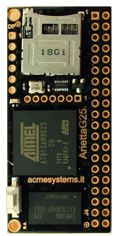
Arietta G25 Features

We can see the layout of the board with the indication of the connectors and the main and additional components.
Let us see the main features:
- CPU Atmel AT91SAM9G25 SoC (ARM9 a 400Mhz)
- Ram DDR2 available in two versions, 128 or 256 MByte
- Power feed: single plug, 3.3 Volt DC
- Digital Levels: TTL 3.3V (doesn’t support the 5V level)
- PCB layers: 8
- Supported for at least 5 years
- Designed and manufactured in Italy
- Connector J4 – Designed to host a connector with two rows of 20 pins 2.54mm spaced (100 mils). In some cases, more functions are configurable on the same pins through the web-guided process, using the file “acme-arietta.dtb” that is in the root partition.
Consequently, the functions described below are not all available at the same time:
- 1 USB host
- 1 hi-speed USB host (shares the lines with microUSB port)
- 1 hi-speed USB host (shares the WiFi adapter lines)
- 3 lines UART
- SPI bus: 1 bus with the ability to select up to 3 chips (5 to 50 MHz)
- four lines:
- 4-channel ADC with 10-bit resolution (1024 “steps”)
- audio interface SSC / I2S
- There are no video outputs or to TFT display, but you can use the SPI bus for small TFT display and the I2C bus for small alphanumeric LCD
- There isn’t a LAN interface directly but the USB ports can be used to connect a USB2LAN
- Connector DP – Prepared to host a 6-pin male connector of 2.54mm (100 mils) to connect the USB / Serial DPI converter (Debug Port Interface)
- Connector WiFi – Ready to host a female connector, 7-pin 2mm pitch to connect the IEE802.11 WiFi b / g / n adapter;
- Slot for Micro SD board (up to 64GB capacity) with the GNU / Linux distribution (bootable)
- Connector microUSB to connect the Arietta G25 to PC and access the system. The port is managed like an USB2LAN emulator (USB gadgets)
- LED configurable by the user
- Button configurable by the user
Software features
- Kernel Linux 3.14.7
- Distros: EmDebian Grip Linux “Wheezy” 7.4
- Programmable in: C, C++, Python, Java, PHP, Perl, Node JS, Lua, Basic, Shell
- GNU C, Python, Perl and PHP preinstalled on the microSD for an immediate use
- IDE Codiad with Web interface, to edit code and programs directly on web browser
- Terminal emulation with web interface “Shell-in-a-box” to remotely manage the system with a command line approach
Documentation and Tools
- Micro SD board with preinstalled GNU/Linux, on sell in the Acme eShop; you can also download the software images for free from Acme binary repository to flash them directly on your microSD boards.
- Step by step guides to compile your own distribution starting from source code
- Open source firmware, free software IDE and toolchain
- Tutorials and code sketches available for free
- Thousands of Open Source packages you can find on Debian Wheezy repository
Let us prepare the Arietta G25 board
For the first use, we recommend to use the board with his WiFi adapter and the FTDI converter to access to the console. Those two tiny devices can be soldered directly on the board or mounted on a 7mm female stripe, 2mm spacing for the WiFi and on a 6mm male, 2,54mm spacing for the serial interface.

We have chosen the WiFi adapter with the external antenna connector. We assemble the pigtail cable and the antenna on the module, and then we plug both modules on their connectors. If we do not think of using any GPIO pin, the board is ready. Now we need to power the board and connect to it for the customizations.
In this case there are several possibilities. You can connect via “serial console”, or connect via micro USB “Device Port”, in which case the board is “seen” as a LAN adapter. We can connect to WiFi using the extension module that we mentioned or finally using a wired Ethernet cabling to GPIO a USB port and using a LAN adapter / USB.
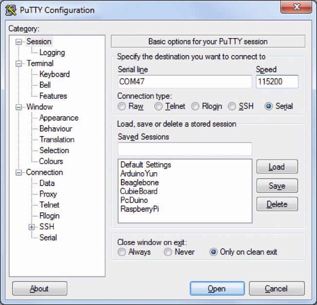
For a first “exploratory” use we still have several possibilities. To begin, let us connect the mini USB cable to DPI serial module. Open a PuTTY terminal on our PC and configure it as shown.
We configure the field “Connection type” to “Serial”. In Serial line, insert the COM port number assigned to the DPI converter. We set “Speed” to “115200”.
This opens the serial communication, currently inactive. Let’s take a couple of returns and we will see red LED flashing on the DPI module. Now connect the Micro USB cable to the micro USB connector “Device Port” and the other side to another USB port on the PC. Arietta G25 will start on boot, and we can see the messages in console.

Meanwhile, being the first time that we connect Arietta G25 via USB, the RNDIS / Ethernet Gadget drivers will be installed for the adapter. If you use a PC with XP or however the driver is not retrieved automatically, you can download it from address
http://www.driverscape.com/download/rndis-ethernet-gadget
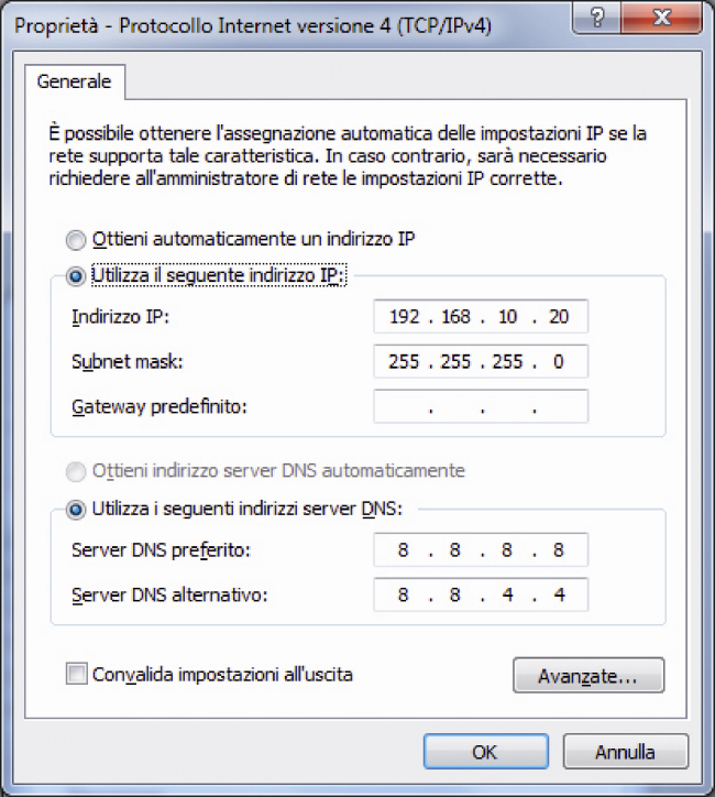
Choose the correct version for your system. Unzip in a folder specially created and run the driver update pointing to the newly created folder. At the end, if you go to Settings >> Network Connections, you’ll see a new LAN connection. Click with the right mouse button on the new tab and select “Properties” from the drop down menu. Here you set the adapter’s IP address and subnet mask with the following values:
IP 192.168.10.20
Subnet Mask: 255.255.255.0
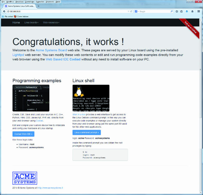
Give all the necessary confirmations and close. Open a browser and type the address 192.168.20.10, which is the default address of the board. You will see the page to confirm that everything is working fine. This page confirms that on the board is activated a web server “lighttpd”, a “light” version of the web server and there are a couple of interesting applications: “Codiad Web IDE” and “Linux Command Prompt”. The applications are accessible from the home page just opened. The userid and password to be used are indicated in the page itself. As easy as that.
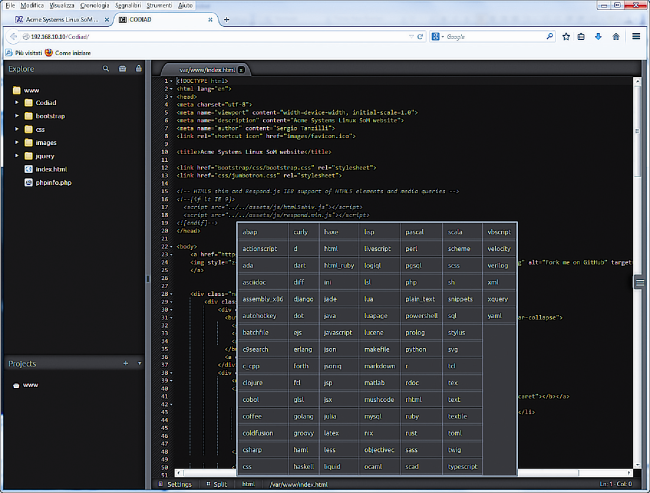
The first is an IDE for development and management of multi language projects that will be very useful in our implementations. To access it, click on the blue button “Codiad Web IDE.” On the next page we insert given userid and password to get the page. As we see, the structure is typical of an IDE. In the upper left corner, the Explore window allows you to browse files and folders that belong to the www folder. The frame at the bottom left allows us to manage projects, while the large window on the right allows editing code. You can highlight the syntax of code by setting the correct language, by selecting it in the rich list that opens by clicking on the
“language tab” in the contextual menu bar at the bottom. You can split the window into different sections and the merge content between two windows.
The second application is a remote terminal via the web. You must sign in with the general user, “acme” in our case. Once inside we have a terminal window useable remotely. As an example, we gave the command that allows us to verify the occupation of partitions:
df –h
The thing is not accidental. The characters “-” and “+” must not be typed using the normal keyboard but the numeric keypad, or, if you use a laptop as it is in our case, obtained with the key combinations that emulate the numeric keypad. In our case simultaneously pressing the “Fn” and “-” associated with the matrix “Fn”. To use the user “root” you must type the command “superuser”
su
and then type root password (“acmesystems”).

These two applications allow us to handle almost the entire board remotely. We continue to analyze the different possibilities to connect the board, via SSH server and via serial console with the module DPI. We check the presence and operation of the SSH server with the command
service ssh status
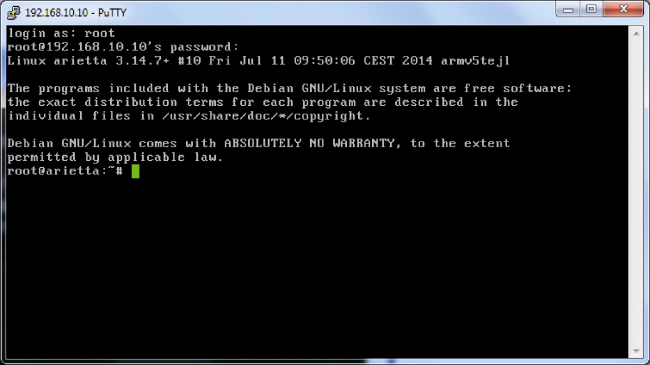
The response confirms that the server is installed in the default configuration and is activated at boot. We connect using the remote terminal “PuTTY” and the remote File Manager application “WinSCP”. The operating system is virtually the same used with Raspberry Pi. To connect with both applications use the board address 192.168.10.10. We execute the login with userid and password and get visible results.

We take advantage of file manager to anticipate a topic that will be essential for the next configurations and customizations. We go to the folder / boot that “points” to the boot partition, and is mounted automatically at boot and let us verify its content.
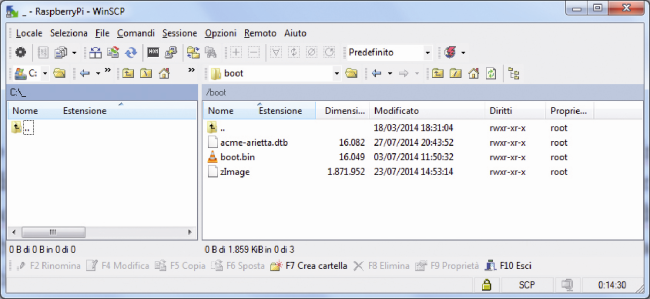
Two files are particularly important. The zImage is the image file of the Linux kernel. It is the result of any compilation processes to customize the configuration of operating system according to our needs. In the website of Acme Systems are available pre-compiled kernel for specific requirements, as if we would enable the analog to digital converter. The file “acme-arietta.dtb” contains the pin configuration obtained from the “web” configurator.
Now let’s go back a moment to the terminal emulator connected to the serial “console”. We can use this window as a window terminal, with some limitations that we will see case by case. The main use of the console is to display all the messages output at boot and shutdown of the system. After login with userid “root” and password “acmesystems” try to give a command:
reboot
You will see that the console does not disconnect, as do the connections via the SSH server. To see the boot messages from the start, just make the connection before powering the board from the micro USB connector. Now we explore the management of GPIO. To know the meaning of the GPIO pins of Arietta G525 the best tool is the Web configurator.
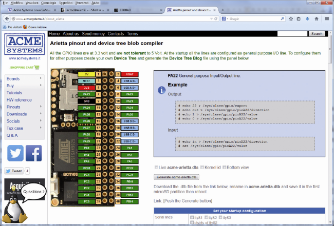
In the basic version we see the default configuration of the GPIO pins. By clicking on any of the pin at the top right of the page we see the description of the pin function. For some pins, instructions to access, read and modify the content of pin are also given. If we want to customize the pin configuration we can use the configuration section on the right of GPIO representation, under the pin configuration. The configuration is done by selecting with a check mark the functions you want to enable. If you do some test, you can verify that some functions share the same pin as ADC and PWM, that share pin 34. 36, 38 and 40. Therefore, we can choose only one of the options, mixed configuration of these pins will not be accepted. Another case is the I2S bus, which requires the simultaneous activation of the I2C bus. In our case, we opted to activate the bus i2c-0 and the ADC.
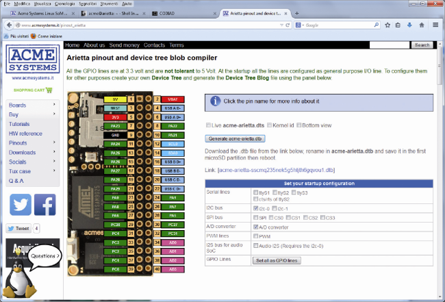
Obtained the configuration we want, we request the preparation of the customized file .dtb by clicking on the button “Generate acme-arietta.dtb”. After creating the file is being proposed a link to download the file on your PC. Now we invite you to check the “Tutorial” site to see if additional steps are necessary. In the subsection “Using the A / D converter lines” we find a surprise. In the Linux image distributed with Arietta G25 is not present the driver Atmel ADC so it must be enabled using the “menuconfig” (see appendix to the book mentioned) and recompile the Kernel. Fortunately in the tutorial there is provided a link to download a pre-compiled kernel that includes the required driver. We download it to a folder on your PC. Now we have to update the boot partition of our board with the two files we downloaded. We decided to use the tool WinSCP that allows us to move and swap files between the board file system and PC.

First we create a backup folder on your PC, move the original files zImage and acme-arietta.dtb to the backup folder. We mount in acme-arietta.dtb the configuration file that we downloaded from the Web configurator. Move the zImage and acme-arietta.dtb to the boot folder. Well check the file names and their presence in the folder. Now we go to the console window and type the command:
reboot
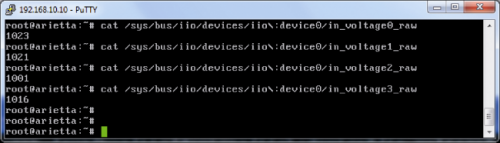
Once completed the boot process, reconnect the Terminal Putty window and check the functioning of ADC converter giving the following command:
root@arietta:~# cat /sys/bus/iio/devices/iio\:device0/in_voltage0_raw
1023
root@arietta:~# cat /sys/bus/iio/devices/iio\:device0/in_voltage1_raw
1022
root@arietta:~# cat /sys/bus/iio/devices/iio\:device0/in_voltage2_raw
1001
root@arietta:~# cat /sys/bus/iio/devices/iio\:device0/in_voltage3_raw
1017
root@arietta:~#
We can also connect a trimmer 4,7KOhm and try to acquire the digital values at different positions of the trimmer cursor, obviously using the command corresponding to the channel ADC to which we connected the trimmer, the first in our case. We should always remember not to exceed 3.3V input to each pin, otherwise we will destroy the board. The inputs of the SoC AT91 DO NOT tolerate voltages above 3.3V.

We see now that we have activated the I2C bus. As a first test of his presence we’re going to verify the presence of the device files in /dev. Effectively we find the file i2c-0, indicating that the configuration operation is successful.

To manage and control at best the I2C bus we should install the i2c-tools package, which is part of the repository of the distribution. To do this we must connect the board Arietta G25 to Internet. At the moment we can use wireless WiFi. We have already connected the module to the board, so we just have to configure the file / etc / network / interfaces to work with our network. In figure is visible a FACSIMILE file. In fact the essential parameters to configure are those for the SSID, type of protection and password. For a connection with WPA you can use the example shown, of course entering the parameters related to your network. For a connection with WPA you can use the following example:
auto wlan0
allow-hotplug wlan0
iface wlan0 inet dhcp
# wpa-scan-ssid 1
# wpa-ap-scan 1
# wpa-key-mgmt WPA-PSK
# wpa-proto RSN WPA
# wpa-pairwise CCMP TKIP
# wpa-group CCMP TKIP
# wpa-ssid “ZyXEL_Roberto”
# wpa-psk “8B6A5F9D1C”
wpa-ssid “AP_FE2”
wpa-psk “8B6A5F9D1C”
This configuration is valid for a secure network with WPA. For a network protected with WPA2 key you can refer to the article “Internet radio with Raspberry Pi and LCD shield” in the number 184 of the magazine and the configuration examples available at:
http://www.lsi.upc.edu/lclsi/Manuales/wireless/files/wpa_supplicant.conf

Once connected to the local network we can install the package i2c-tools, or all of the packages that we want. We update the database package, and the distribution itself, with the commands:
apt-get update
apt-get upgrade
Then we install the package with command:
apt-get install i2c-tools
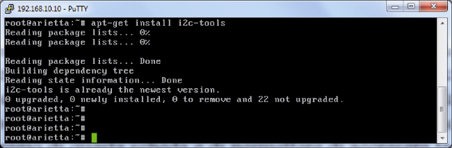
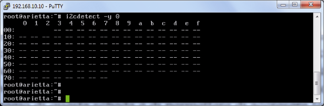
Finally we verify the proper installation of the driver I2C with command:
i2cdetect –y 0
that will give us the results as shown in figure. Just a warning. You have to give the command from a terminal window open with PuTTY, or from the web terminal “Shell in a box”. If you give the command from the serial console terminal, you will get error messages. Do not be alarmed … and change window.
At this point we can say to have made acquaintance with the board Arietta G25 and the principal ways to access and manage it. The value of this board is that it allows to increase your skills in embedded GNU / Linux pretty easily, by guides and tools provided by manufacturer Acme Systems, which make the learning process even entertaining, without the “frustration” often accompanying those who goes deeply into GNU / Linux without proper guidance. For now, if you are going to base your future, even in part, by focusing on the digital evolution of our world, do not miss this opportunity.

I has question! Would it be possible to make a cluster (hadoop, others) of those little things? How much will it cost? Where can I buy it? Thank you.
https://store.open-electronics.org/index.php?route=product/search&filter_tag=arietta
I bet this thing cost over $50.
You lose
https://store.open-electronics.org/index.php?_route_=Linux_Embedded/ARIETTAG25256
Hi, I’ve tried to download the zimage and .dtb file for ADC operation, and I’ve tried to replace the original ones with those files downloaded from acmesystems.
The systems seems to restart cause the led blink right but with the new zimage and .dtb files I cannot reach the IP anymore, the PC doesn’t see any network card like before.
Thank you
Could this be a solution for small, embedded Android in commercial apps?
[…] 2. Arietta G25 – The Embedded Linux Board […]