- Building a 3D Digital Clock with ArduinoPosted 4 months ago
- Creating a controller for Minecraft with realistic body movements using ArduinoPosted 5 months ago
- Snowflake with ArduinoPosted 5 months ago
- Holographic Christmas TreePosted 5 months ago
- Segstick: Build Your Own Self-Balancing Vehicle in Just 2 Days with ArduinoPosted 6 months ago
- ZSWatch: An Open-Source Smartwatch Project Based on the Zephyr Operating SystemPosted 7 months ago
- What is IoT and which devices to usePosted 7 months ago
- Maker Faire Rome Unveils Thrilling “Padel Smash Future” Pavilion for Sports EnthusiastsPosted 7 months ago
- Make your curtains smartPosted 8 months ago
- Configuring an ESP8266 for Battery PowerPosted 8 months ago
ArdIR a programmable and remotely manageable Infrared control with Arduino
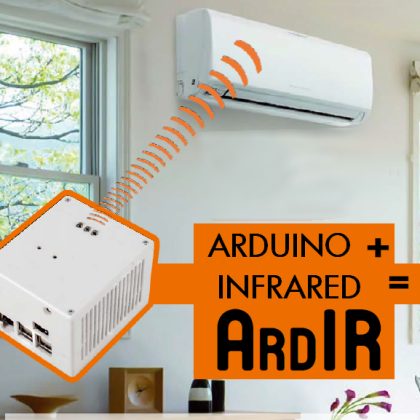
This project presents a universal infrared remote control that can also be managed via Internet, based on RandA (supplied with a dedicated shield) and on Raspberry Pi2.
Despite the fact that still only a few people take advantage of the “smart” revolution in home automation (intended as a complete and integrated automation and computerization of the devices in our homes), it must be said that the number of such applications grows day by day, and that they offer a solution to many big and small problems of everyday’s life. The ArdIR project we present in these pages is a very particular application in domotics, since it simulates the remote control for the TV, for electrical appliances and for air-conditioning, by sending the same data those would be sending to the wanted device. However, it is entirely programmable and remotely manageable, since it can be “seen on a network” such as a Web Server showing its own pages, to which to connect to give orders.
With such premises, it appears clear that its “elective” usage is to control the air conditioning system: those who are away from home may connect to the Internet to turn it on, and giving time to it, so that it may bring the temperature to the wanted level before our return. But even if staying at home, there might be need to control a device (such as the television or the stereo) from different rooms, without having to move. Finally, ArdIR can be used as simple substitute for the remote control, in the case this was out of order; or in order to exceed its coverage limits.
Operating principle
At the basis, ArdIR operates as a common “universal” remote control: in the beginning, it needs a learning phase to memorize the codes of the remote control(s) and after, when required, the said codes are sent to the device to be managed. The plus resides in the fact that ArdIR is not driven by a physical keyboard, but by a “virtual” one, presented on the HTML/JS page, and shown by its Web Server with HTTP protocol. Therefore it can be seen by connecting yourself with a smartphone, or via PC by means of a web browser.
At a practical level, we have to consider that, as a principle, the hardware system could simply be composed by Arduino, to be connected to an appropriate shield supplied with a receiver (for the learning phase) and with Infrared LED emitters. To add the network connectivity, however, Arduino is not enough: our choice therefore fell on the usage of the RandA board, that we presented a few numbers ago on this magazine. It is as easy to use as Arduino, and adds to it the computing power and the amount of memory offered by Raspberry Pi and Arduino, as “separated” boards. To all of this, RandA adds different advantages:
- the installation of Raspberry Pi’s software includes different libraries to communicate with Arduino and to simplify the integration between the two systems. For example, Arduino may send Linux commands directly to the Raspberry Pi and write/read files on it;
- Arduino’s programming may be carried out by means of Raspberry Pi, whose software supplied also includes the IDE; but another IDE is also available, for a “modified” PC capable of connecting remotely to Arduino, when Raspberry Pi is connected to a network;
- included in the software package, which is configured and immediately operative, there are: the web server that supplies different applications and sample web pages as a base to develop your applications;
- a real time clock (RTC) has been added, and supplied with a backup battery, it is useful if you want -for example- to schedule the devices’ activation on a time basis;
- from the point of view of the hardware, the system as a whole proves to be more compact: it can be powered by a single source and there are no “loose” wirings connecting one board to another.
With such an “equipment”, the only hardware board yet to develop is the shield with the interfaces needed for the infrared communication. We shall describe them in detail now.
Shield’s circuit diagram
The figure shows the the ArdIR shield’s circuit diagram, that certainly proves to be simple, both as a concept and as for the number of needed components.

Starting from below, we notice the IR1 infrared receiver, whose output is directly read by Arduino/RandA’s D6 line, during the learning phase, from the “original” remote control. The very well-known DS18B20 temperature sensor is connected to D11, so to return the environment’s temperature to the user. By still going up, we reach the T1 bipolar transistor, used as an electronic switch controlled by the D5 line (configured as an output), that is programmed by the sketch so to apply the modulated signal, which is relative to the channel we want to broadcast. The choice of D5 was not a random one, since it corresponds to the TCCR0 timer’s output, used to acquire the modulation frequency.
The LD3÷LD5 infrared diodes (driven by this signal) send the data in the form of infrared light pulses: with a 5V power supply and a (R5) series 22Ω resistor, the direct current in the diodes’ series is confirmed at about 50mA, a value that allows a transmission at a distance of about two-three meters (the exact range also depends on the alignment among the photodiodes and the receiver, and on the sensibility of the latter). To further increase the range, the power must be increased, and that can be achieved (by decreasing the electrical resistence’s value and/or by increasing the voltage), provided that the duty-cycle of the signal applied to T1 is reduced (by decreasing the ratio between the starting and switching off times) in order to avoid damaging the same diodes. A yellow LED (LD6) is also connected to the T1’s base, and it is used to monitor the execution of the transmission cycles (it will flash quickly during the transmission).
LD1 and LD2 LEDs are needed in order to display the system’s status during the execution of the various phases (as we will explain later), while P1 and P2 are needed in order to give orders, specially if concerning the acquisition phase (and they will be seen in detail later, as well).
Finally, U1 is an EEPROM memory, managed via I²C bus, and needed to memorize the codes of the acquired channels: by using a 24LC256 (32 kB) type memory, up to 127 different codes can be memorized. We had to recur to an external memory since Arduino microcontroller’s internal EEPROM has a limited capacity, one that doesn’t allow the memorization of more than four channels.
Let’s pass now from the hardware to the software, by going to see how the shield we just described is managed.
The sketch for Arduino
Download all files from our repository.
The program for Arduino resident in RandA has been developed as a finite-state machine, whose diagram has been summarized. From the idle state, with both LEDs turned off, it keeps waiting that a button is pressed or that a command arrives from remote (from a web page, that -as we will see later- from Arduino’s point of view corresponds to receiving some characters on the serial port).
By pressing P1 we enter the acquisition mode from the remote control: the red LED will flash, thus informing that the user has to click the key (on the virtual keyboard of the web page) he wishes to associate with the remote control’s code that will be acquired. If the operation is not completed within ten seconds, the phase will be aborted and the system will return to the wait state. Vice versa, the LED will turn on with a fixed light, to indicate that the wanted button on the remote control has to be pressed (after having “pointed” it towards the IR1 infrared receiver, at a distance of about 10 cm), so to send the code to be acquired. Once this has been done, the green LED should turn on for about five seconds, so to indicate the correct learning of the new code. Even in this case, a time-out is present: if within a short time the infrared signal doesn’t arrive, the red LED will flash three times so to warn about the operation being unsuccessful, then the machine will return to the wait state.
Please notice that the acquisition phase can only be activated by pressing the P1 button, and not from the web page. This solution has been chosen mostly in order to avoid that, by remotely activating it by mistake, some channel may be overwritten. Anyway, having to press the button is not a problem, since we have to be near to the board in order to “point” the remote control (from which to learn the codes) at it.
Let’s return to the diagram: if from the wait state we press P2, the red LED will flash two times so to indicate that the local mode has been activated, meaning that the acquisition and communication operation can be carried out by acting on the two buttons, thus without having to connect “remotely” by means of the web page. This option enables the usage of the system in the “stand-alone” mode, for example to make a quick operation test, even when we are far from a PC.
The only limitation is that we do not have the virtual keyboard, and therefore we chose that learning or communicating will regard the first channel only. The operating mode is clear from the diagram: once we enter the “local” operation mode, by pressing P1 the acquisition phase will be activated, with the red LED turned on with a fixed light, waiting to receive a code from the remote control (the code will then be saved, as we explained before, on the number one channel). On the other hand, by pressing P2 the red LED will flash three times and the IR communication will then be activated.
Finally, if from the wait state a command is received from remote, the IR communication is activated for the channel whose number is specified by the command itself (that obviously corresponds to the relative button clicked on the web page). A command has then been added, and it is identified by the (number of channels +1), that asks Arduino to read the temperature from the DS18B20 sensor and then to send it back to the web page.
Reading the remote control’s data
The common infrared remote controls (from televisions, decoders, video recorders, etc.) work by associating each pressed key to a binary code that is then sent serially (one bit at the time) by using different encodings (OOK, FSK, etc.) and by modulating the light emitted by the infrared transmitter with a certain carrier frequency (typically 36÷38 kHz) so to minimize the possibility to be disturbed by environmental light sources that (since they are “noises”) have continuous components instead, or “random” frequencies.
The modulation being used the most is certainly and by far the OOK (On-Off Keying, about which a large documentation can be found on the Internet) one. For each bit to send, the modulator/transmitter will check its value: if it’s 1 it will be sent by an infrared pulse train to the frequency of the carrier; if it is 0, on the other hand, the trasmitter will be turned off (or vice versa).
The receiver, on the other hand, is “attuned” so to recognize this impulse train only if it has a frequency corresponding to the carrier one, and to send a value as an input. The value will be ‘1’ (or ‘0’) if it is detected, and ‘0’ (or ‘1’) otherwise. Basically, the start signal can be found at the output, thus “cleaned” of the carrier frequency (thus called demodulated signal).
In our shield this demodulated signal can be found on the IR1 output, which is a receiver designed to operate with 38 kHz modulated signals. The figure shows the oscillogram of the signal detected (on the IR1 output) by a remote control for a television, and a “zoom in” made to detect the duration of the single bits.

At the software level, the sketch contains a “real time” section, in order to be able to acquire these signals and in addition to the implementation of the state machine we just described. That is to say, it has to be executed at very tight and regular time intervals, so to guarantee that the signal may be sampled and correctly reproduced, and without losing information. For such a reason that code has been embedded in an Interrupt Service Routine called by the microcontroller’s Timer1, whose simplified diagram (restricted to the acquisition part) can be seen in figure.
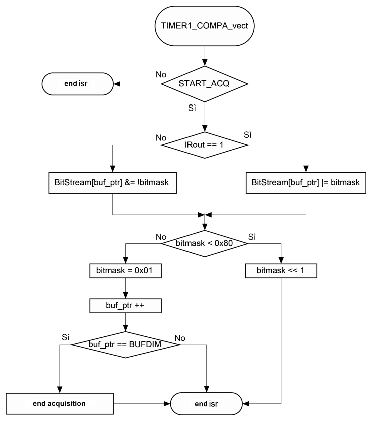
The time interval has been chosen so that it is short enough, in order to sample any signal that may come from the remote control, without “losing” information bits. Theory teaches that the (minimal) sampling frequency has to be equal to twice the input signal (in the case of a digital one this is true if the duty-cycle remains at about 50%, however). Relying on the wave forms, we decided to opt for a sampling period of 100 µs, which is certainly inferior to the analyzed data interval. During the learning phase (the flag ‘START_ACQ’ is active), for each sampling the input line status depending on IR1 is copied and memorized in one bit. Every eight samplings a new data byte of the Bitstream[] vector is created: it is a ‘long’ BUFDIM (a constant stated within the program) byte. Thus, the number of bits that we can memorize is equal to BUFDIM * 8 and the input signal duration may be up to 100µs * BUFDIM * 8. At present, we stated a 256 (BUFDIM) elements vector, thus the remote control’s working signal may last up to 200ms, which is more than enough, given that just a few tens of ms are needed in order to send a command. The remote control’s code, for example, is sent in just 60ms, and then repeated later (and until the button is kept pressed).
On the other hand, in the communication phase (the flag ‘SEND_IR’ is active) the BitStream[] vector is read bit by bit, in the same sequence it was written and at the same rate (100µs): thus the reproduced ‘bit stream’ will necessarily turn out to be identical to the one previously read. These bits are needed in order to turn on and off the PWM output of the T0 (Arduino’s D5) timer, which is programmed so to reproduce a square 38 kHz wave. And thus we will end up with a bit sequence that has been modulated at such a frequency, capable of driving the shield’s infrared diodes, by means of T1.
Web Interface
As we said before, to communicate with the sketch from the outside of Arduino’s “domain”, we took advantage of the “other half” of RandA, that is, Raspberry Pi and the software tools made available by the Linux world. In particular, among them is the Apache Tomcat program: it is a web server, or better a web application server since in addition to managing all the server’s functions, it enables the execution of programs (written in Java and identified as servlets in this context), on the basis of accurate calls remotely made by the client. Without delving deeper into details (the whole documentation needed to examine the various concepts in depth can be found on the Internet), we shall only say that, among other things, the usage of these programs enables the management of Raspberry Pi’s serial communication, and therefore the communication with Arduino. In our case we will take advantage of the “SerialIO” servlet, supplied during RandA’s software installation, since it is already used by other web pages (Arduino Console, Arduino I/O management, etc.) that are included in the installation. This servlet accepts the requests coming from the client (we will shortly see how) and filters them on the basis of the “cmd” parameter, in order to call the corresponding function that in turn will send the information on Raspberry Pi’s serial port, towards Arduino. Following the communication, it waits the (possible) reply coming from the serial port (and therefore, from Arduino) and sends it back to the client. To better understand the details (if you know some Java), you may naturally edit the servlet’s source (SerialIO.class) that can be found in the /home/apache-tomcat-7.0.47/webapps/RandA/WEB-INF/classes/ArduIO folder. Just keep in mind that, if you want to modify it at leisure, it is needed to deploy it again on Tomcat (talking of which, we refer you to the guide, that can be found on https://tomcat.apache.org/tomcat-7.0-doc/appdev/deployment.html).
In figure we can see the general plan of the data stream and the actors taking part in it, from the web page to Arduino’s micro. In it we may notice the SerialIO servlet’s interface function, between the web server and Raspberry Pi’s serial port (described by /dev/ttyS0).

In the same picture, we may now “move” ourselves towards the left to reach the client-side, that is to say the web page to be displayed remotely. This page is divided in two parts: a global one made in html, which is used, more than anything, for the purpose of building the introduction (that is to say, the graphics), and a javascript code section that deals with the events management (basically, “clicking” on the keys) activated by the user.
The mechanism that has been used is a very simple one: for each key in the graphical interface a javascript function is associated, and it will be activated every time the button is pressed. This function may carry out in local processing (on the client machine). In our case, in which we want to send commands to the RandA board, the function will in turn call the ajax() function that, with appropriate parameters, establishes a talk with the server; or better, with the SerialIO servlet. More specifically, the client sends a request to the server that (as we have seen) will activate a function on the servlet: this one will in turn convert it into serial communication to Arduino. The latter’s reply, by following the course in reverse order, will then be intercepted and returned by the same ajax() function (under the form of a characters string), so to be possibly displayed and to give to the user the result required, or at least an answer concerning the operation’s outcome.
System’s preparation
Let’s move onto the practical side of the matter: the first thing to create is the ArdIR shield, by welding the few components needed on the dedicated printed circuit board. There are no critical issues (all the components, that can be easily acquired, are in a “traditional” format) and thus the recommendations are the usual ones, concerning the assembly of the electric components (above all, please pay attention to the polarities!) and we will not repeat them again here. The only advice is the one to not weld the LD3, LD4, LD5 infrared diodes too close to the board, but to leave the legs with a length of at least 1-2cm, so to optimize the bearing towards the device to be managed.
As regards ArdIR’s sketch programming on Arduino’s micro, after having powered and connected RandA to the local network, so to access it via TCP/IP, we may choose to proceed in two ways:
- to install Arduino’s modified IDE (included in RandA’s distribution) on PC: it allows to “see” RandA’s Arduino board at the corresponding IP address (please verify that it is selected on the menu: Tools → Serial port); later it is enough to load the sketch and to program Arduino as usual;
- to use Arduino’s IDE for Raspberry PI: please connect to RandA via ssh (for example, by using MobaXterm) and transfer the sketch on the file system (for example, in the home/pi/sketchbook/ folder); later it can be opened and compiled by means of the “local” Arduino’s IDE.
In this last case, Arduino is “seen” on the /dev/ttyS0 serial port (the only one to be available).
In any case (and if you never did it before), you should also download the OneWire library (needed for the DS18B20 temperature sensor’s management) and copy it in the libraries folder found under the IDE installation folder (if in Windows), otherwise in /usr/share/arduino/libraries (if on Raspberry Pi). On the other hand, the other libraries for the project are already included with the IDE for both platforms.
Please notice that Arduino’s IDE for Raspberry Pi should be included if you managed to obtain a SD-card with the RandA system that is already installed; otherwise, please make sure that the board is connected to the Internet during RandA’s package installation, since Arduino’s tools are downloaded online. To verify that, please type on a Raspberry Pi console the following command:
ping 8.8.8.8
where 8.8.8.8 is the IPv4 address of Google’s primary DNS server. If the result is a positive one, then the Raspberry Pi board “sees” Internet.
After having made some tests, we advice to use the first method: Raspberry Pi’s IDE is certainly slower, especially during the compilation, but on the other hand the computing power cannot be compared to that of a PC!
Once the ArdIR sketch has been programmed and its shield has been connected to RandA, a first system test may be immediately carried out. First of all we may verify that, after each reset (or after each programming) the red LED will flash three times, so to indicate that the sketch is loaded and ready to use. Please press P2 afterwards, until you see the red LED flashing two times, in order to enter the local operating mode. At a later stage, we will press P1 so to enter the acquisition mode, and the red LED will turn on with a fixed light: we will then point the remote control towards the IR1 receiver (at a distance of 5-10cm), and we will activate the command that we want our board to learn (for example, switching television channels).
The red LED should turn off, and the green one should turn on instead, to confirm that the operation was successful. Otherwise, please repeat the operation. If, for one more time, a positive ending isn’t reached, please verify that the remote control is working and that the carrier frequency is of 36-38 kHz; if in doubt you may try with another remote control.
Assuming that the operation reached a positive ending, after five seconds the green LED will turn off and we will return to a wait state: let’s try then to send the command we just acquired towards the device we used. We will take care that the infrared LD3-5 LEDs are pointed towards the device, at a distance that possibly does not exceed a meter (at least for the first test). Let’s press P2, then, until we see the red LED flashing two times, and after that let’s press P2 again: the red LED will flash for three more times, and upon completion a communication towards the device will be carried out. Please notice that, at the same time, the blue LED will have to turn on briefly. If the “test” device executes the command (the one that we wanted it to acquire), we may consider the test as complete.
Let’s transfer the control on the Web
With the last implementation step remote access to our board is gained: as we have already seen, we will take advantage of RandA’s web server (Tomcat), in order to give visibility to the html pages that we want to make publishable on remote clients. Consequently, at an installation level we just have to worry about putting them in the folder below:
/home/apache-tomcat-7.0.47/webapps/RandA/
from where Tomcat will take it to transfer it to the client requiring it.
The page specifically created for this application, that we called IRConsole.html, may be seen infigure: the graphical style has been set along the lines of other web pages that have already been created for RandA’s remote control. Moreover we added its reference on index.html (that allows to open other pages by means of the applications for RandA’s remote management) as well, so that it may host the connection to our IRConsole.html.
Once the pages have been loaded in the abovementioned folder, we may immediately verify that they are properly working, by means of a PC that is connected to RandA’s local network, and by typing in the browser’s address bar: http://<Indirizzo IP RandA>/RandA/IRConsole.html,
<Indirizzo IP> here stands IPv4 address of RanA’s board within the LAN. The page shown in figure, should then be loaded, and as we already said it corresponds to the IRConsole.html file that we loaded previously.

The first key may be immediately noticed on this page, it is connected to the serial communication: it is needed to activate the communication channel, from the servlet to the /dev/ttyS0 serial port (and therefore to Arduino). Therefore, it is the first thing to activate, and then we have to wait that the window on the side will state “open”. It is worth to remember that Arduino’s serial port is also used for programming, thus if we activated the communication with the web page we cannot program the board and vice versa. In order to avoid leaving the serial port uselessly busy, it would also be a good practice to remember turning off the the interface (by using the key again), before leaving the web page.
Immediately under that, we placed a list of the keys corresponding to the various channels in our virtual remote control; speaking of which it must be said that it is possible to add more of them (and up to 127) and maybe to customize their names, so that they may describe the associated function (for example, “turn on the air conditioner” instead of “Channel 1”). To do so, the IRConsole.html file must be edited, and the code between the two comments, <!–Channel list begin –> and <!– Channel list end –>, must be modified. To change the name, it is enough to change the relative field, “value”. For the sake of clearness, the procedure needed to add the buttons is described separately within this same article (in the box named “How to add channels to our remote control”).
After the list of the keys/channels, there is the “Processing status” box, that relates the outcome of the communication with RandA: for every command given, it will show “wait” while waiting the reply, “fail” if the command was not executed or if Arduino didn’t reply within a certain time (there is a timeout on the SerialIO servlet), or “OK” if the command was successfully executed. By going down in the web page we encounter two buttons we will describe below.
- Get room temperature: for each “click” it updates the temperature value detected by the DS18B20 sensor that is found in the shield. This information can be useful if we use ArdIR to control the home air-conditioner. Please keep in mind that at the first query, since there are no valid conversions yet, it might show the default value (85°C): do not worry, but click again.
- Arduino reset: it forces a reset in Arduino’s micro. In the case of (unlikely) need, it enables the “restart” of the sketch.
The “HOME” link, finally, has been “borrowed” from other RandA’s web pages, and allows to return to the home page shown in figure.

It is quite easy to replicate an infrared remote control’s code, by using a few components and an Arduino board. On the other hand, by using RandA, other possibilities are added, such as the Web access and the remote control.
From the store
RandA: the union from Raspberry and Arduino
FT1219K

Related Posts


2 Comments
Leave a Reply
-
 Arduino ISP (In System Programming) and stand-alone circuits
We use an Arduino to program other ATmega without...
- Posted 12 years ago
-

-

-
 GSM GPS shield for Arduino
Shield for Arduino designed and based on the module...
- Posted 12 years ago
-
 Small Breakout for SIM900 GSM Module
Some post ago we presented a PCB to mount...
- Posted 13 years ago
-
 Join Maker Faire Rome 2024: Innovation Unleashed at Gazometro Ostiense | Calls Now Open!
All Calls Now Open for Maker Faire Rome 2024...
- Posted 2 weeks ago
-
 Building a 3D Digital Clock with Arduino
Project to create a digital clock consisting...
- Posted 4 months ago
-
 Acoustic amplifier – in DIY Kit
This kit creates a microphone amplifier with an output...
- Posted 5 months ago
-
 Creating a controller for Minecraft with realistic body movements using Arduino
Project of a controller that maps body movements...
- Posted 5 months ago
-

Pingback: Supreeth (supreeth128) | Pearltrees
Pingback: Control all your IR appliances through Bluetooth (or internet) | Open Electronics