
A Bluetooth enabled remote that will help you control one or more IR-controlled electric payloads.
In this post, we are going to present a project for emulating an IR remote control composed of a RandA board (an Arduino that has connectors to interface with Raspberry Pi on one side and connectors for Arduino shield on the other) and a dedicated shield (ArdIR), that allows to control house appliances by reproducing the signals emitted by respective controllers. The peculiarity of this project is the possibility to control them remotely, via the internet, thanks to a dedicated web interface that can be accessed via the browser of devices connecting to it. Given that we had used an Arduino shield for that project, we thought it could be a good idea to use it again by reviewing the entire project from an Arduino perspective, that is by taking off Raspberry Pi and RandA and applying the shield directly to an Arduino Uno board. And…voilà! In these pages we will see how to control the ArdIR shield through a Bluetooth connection, therefore a close range one; this means that the “remote” controlling device will have to operate inside the same building of the system’s, at a distance not over a few meters, especially if there are big walls interposed between transmitter and receiver. This requirement may appear as a limitation and may lead to asking why did we choose this system. Well, if one needs to manage some devices inside one’ house although out of line of sight of classic IR remotes (e.g. if you want to listen to the music on your Hi-Fi which is in another room, and you want to be able to control volume, track, etc.), Bluetooth communication may be the most convenient because it doesn’t need an active LAN (with router and Wi-Fi to connect to mobile devices); connection between devices is direct (point-to-point), provided that each is equipped with Bluetooth interface. This is (almost) always true nowadays for tablets and smartphones, which in this project act as controlling devices; in the controlled device, that is the system composed of Arduino and the ArdIR shield, this is not the case because generally, Arduino doesn’t have this interface. We opted for a shield available as a kit (code FT1032M).

In Figure we can see a recap of our Bluetooth remote controller; the user can utilize any mobile device (equipped with Bluetooth interface), through a dedicated app that we are going to analyze below, to send the desired commands; these will be radio-transferred to the Bluetooth shield, thus making them available to Arduino which, through the dedicated sketch, will manage the ArdIR shield to emit the infrared signal direct toward the device to be controlled.
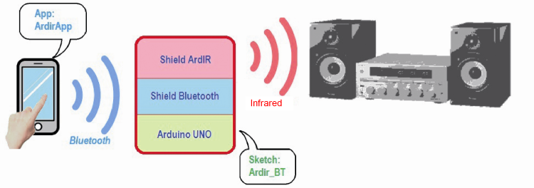
On a logical level, the figure shows, on the other hand, the hardware/software “Andes” involved in the data exchange between the devices.

Now that we have established the scenario, that takes a look at the application software (app and sketch) responsible for the functioning of the respective parts. Ask for a detailed description of the two shields (and to also get to know their pros and cons) please see this post (bluetooth shield and IR shield).
The ArdirApp application
This application has been developed for Android systems, therefore it can be installed on devices based on this platform, starting from version 4.1 (jellybean). The development environment employed is Android Studio, recently sponsored by Google as official software for developing Android application instead of Eclipse.
From a user perspective, our app needs two phases to be handled:
- Research and connection to the target Bluetooth device, i.e. shield FT1032M;
- Selection of the channel to be activated, for transmitting the code to the shield FT1032M.
from a programmer perspective, in order to execute the bow, we need to structure a program composed (at least) of the main class, in charge of handling starting activities (graphics and resources initialization) and events management (callback of the user interface buttons) that we have called “MainActivity”. Bluetooth handling, on the other hand, is assigned to a separate class called “bt_Clientclass” in order to keep the code clean and easily maintainable.
The logic flow of “MainActivity” behavior is outlined in the figure; at launch, after assigning and initializing the various resources, the program verifies the presence of the Bluetooth interface; if the interface is not enabled, the program asks the user to do so. If the user denies, or if said interface is not detected on the device we are using, the program will terminate. ViceVersa, once the interface is enabled the program will allow access to the list of active Bluetooth devices nearby Colin and the user will have to select the one he desires common in this case, we are selecting the RN42 module of the Bluetooth shield referring to the system the ArdIR is connected to. After that, the program will learn the physical address (MAC) of said device and will be able to connect through the connect() method defined in the “bt_Clientclass” class.

Once the connection with the Bluetooth shield is established, our app will wait for the user to select one of the available channels on the graphic interface, which will then be transmitted via IR from the ArdIR shield. When this happens, the message formed by a precise number sequence is created, which contains the code for the children channel, at the same time we call the write() method from “bt_Clientclass” class, which is in charge of transmitting said data via Bluetooth.
Once done that, the program is ready to handle a subsequent command by the user and will be listening to possible messages returned by the remote Bluetooth device. In our case (similarly to what would happen on the web controlled version) this data can come from Arduino which, after receiving and processing the command, will activate the ArdIR shield and transmitted back the result of the operation via Bluetooth using character strings (“OK”, “Fail” or the temperature value requested). Therefore, this strings will be received by the app directly displayed on the user interface.
Please note that the message reading thread is separated from the main program flow: this way, we can avoid a crash if the return message is not received for some reasons. To be precise, we are using an android mechanism employed for exchanging data between different threads, that is the message queue (MessageQueue): specifically, we have allocated a handler-type object in MainActivity and then transmitted its reference to “bt_Clientclass” class (when the object is created); the latter will use it in order to transmit messages containing information and data coming from Bluetooth, thus automatically triggering the handler method call handleMessage() and making the message available to MainActivity that will finally put it on the display.
Let’s now analyze functionality of class “bt_Clientclass” that manages the Bluetooth, dedication to Arduino by configuration of the device (as the name itself says) as client peripheral, while the Arduino side will act as server (specifically, the base architecture has been modified from the “BluetoothChat” project, a demo on Bluetooth communication available on the website www.developer.android.com). The logic diagram for functioning can be seen in the figure; since this is a “service” class to the main application, we illustrated only the interface methods that refers to the flow diagram shown in previously.
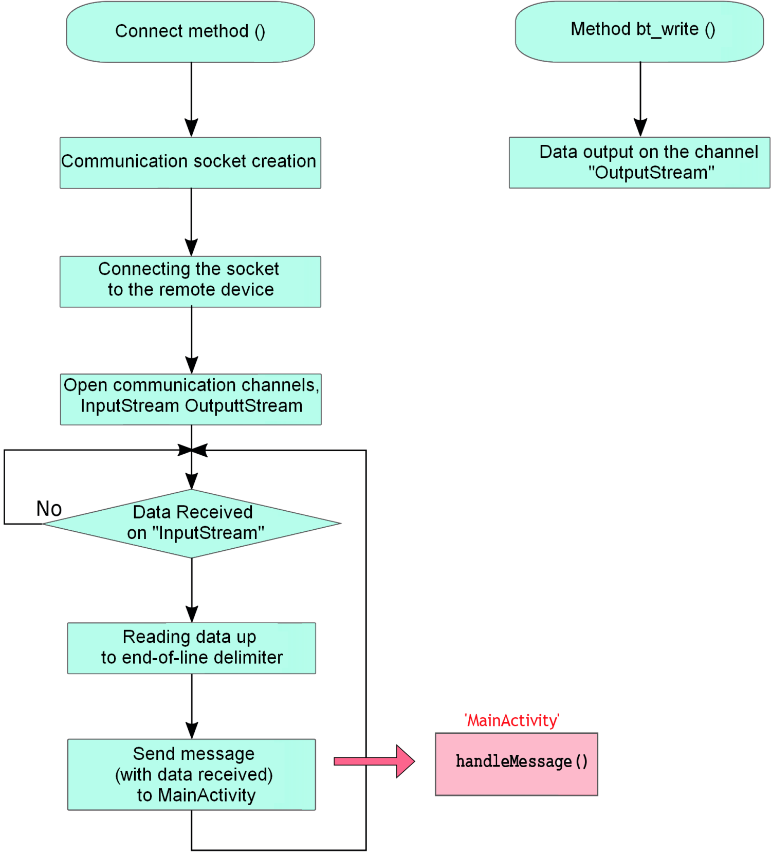
By calling connect() method from MainActivity we establish Bluetooth communication which, in Android, once identified the device to connect to (and their relative address), is done in two steps:
- A communication channel (socket) to the server is opened;
- Connection to the socket.
In the first step, we try to establish a connection to the device relative to the specified address, using the createRfcommSocketToServiceRecord() method of “android.bluetooth.BluetoothDevice” class; said method requires to transmit a universally unique identifier (UUID), i.e. a unique 128-bit number for each device in the Bluetooth network we are working in. In our case, in order to connect to the RN-42 module, we use a preset “generic” UUID. As the name implies, the China we are asking to open is an RFCOMM channel (a communication protocol “simulating” an RS232 serial port), which the Bluetooth profile SPP (Serial Port Profile) is based on. This type of protocol is one of the most commonly used for transmitting data between devices using Bluetooth, says it is used by many applications that were designed to make use of the serial port for communication and it is supported by all the main operating systems on both mobile and non-mobile devices.
Back to our program, after successfully creating and opening the socket, we call the connect() method in order to activate the connection to the server; even if this fails, communication is established and ready to exchange data between the parts. To do so, we associate to objects of types “InputStream” and “OutputStream” to the socket on which we will work in order to read and write data.
If we take a look at the code, we can notice these procedures are executed within two nested classes, called “ConnectThread” and “ConnectedThread”. These classes, which extends the Thread class, have been indeed used to handle connection and communication stages within the two respective threats, which executions are independent of that of the main program: this way we can avoid crashes in case of connection problems or communication problems with this Bluetooth server. Moreover, because of this we can notice how, in the flow diagram, once connection stage is over the code stays “hibernated” waiting to receive data from the Bluetooth, on the “InputStream” object; given that this is executed we’ve seen a thread, this does not compromise the main program functioning. Therefore, we can say that data reception logics is handled by a process running in background, asynchronously and independently from the main application. When the server (managed by Arduino) transmits the data string, it will be recouped old the code until it receives the end-of-queue character. Now the process will use the handler provided by MainActivity in order to transmute the receipt string, in the following manner:
- creation of a message by: obtainMessage() and passing the data string;
- from the instance of the message just created, SendToTarget() method is called; this will trigger, as mentioned above, activation of its “counterpart” (the handleMessage()) of the handler, that will make the data available in the MainActivity class since it is implemented within that class.

On the other hand, in order to transmit data to Arduino, MainActivity only has to call the bt_write() method, passing as argument the data vector we wish to send; this will be then transmitted to the Bluetooth peripheral through the write() method of the previously initialized “OutputStream” object.
Sketch ArdIR_BT
On the Arduino side, as mentioned above, we have the ArdIR shield that is handled thanks to a firmware largely derived by the ArdIR.ino sketch, also explained in the article relative to the above-mentioned shield; for this reason, we will focus our attention on the changes made from that sketch.
This time, the Arduino serial port is connected to the RN42 module of the Bluetooth shield, therefore, we have to manage communication with shield accordingly, with a communication speed of 115,200 Bauds, as well as a possible initialization stage. For this reason, the serial interface is probably initialized within the setup() function of the shield, then only “minimal” info is transmitted to the RN42 in order for it to work correctly, that is by setting it on SM0 mode (see the module manual for more info) so that it will act as server in communication towards Bluetooth devices.
From a functional perspective also, the program perfectly recreates the behavior of the original “ArdIR.ino”; its state diagram is illustrated in Figure.
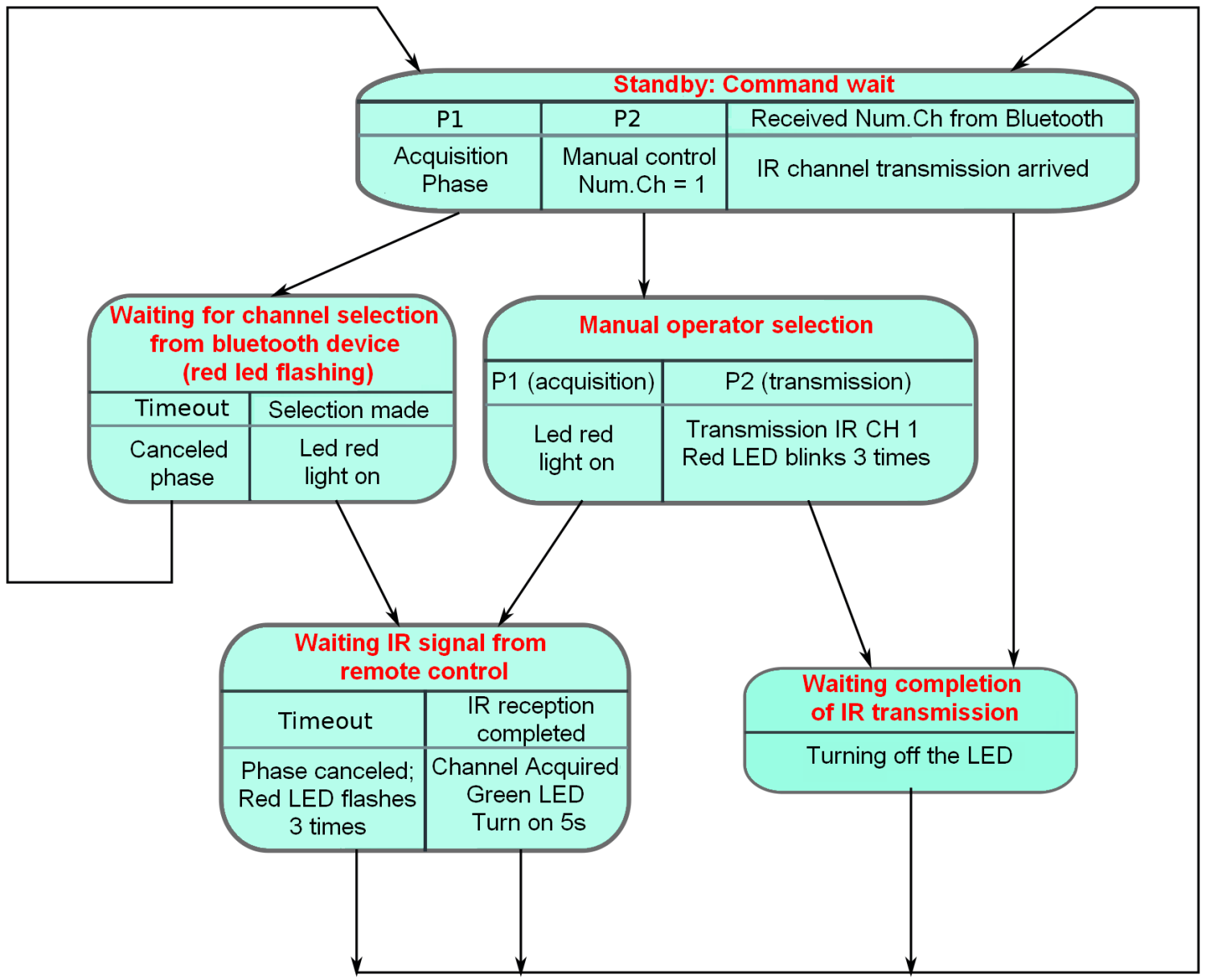
Let’s briefly recap the function and logic: we start from the waiting stage, in which both LEDs of the shield are off, and we wait for an action to happen, which can be:
- Pressure of P1 key on the shield, in which case code acquisition stage of one channel of the remote control is activated; this way the key (channel) activated by the app is associated with the infrared code that we want to transmit to the receiver (TV set, etc.); below, we will describe the practical operations to carry on;
- Pressure of P2 key on the shield; acquisition and transmission of the first channel is managed “locally”, that is without help from the remote Bluetooth device;
- Reception of a channel number from the Bluetooth module (therefore from a smartphone/tablet equipped with the app mentioned above); this is the “normal” functioning stage of the system, in this case, IR transmission of the code associated with the channel of the previously acquired remote control is activated.
From theory to practice
Now, let’s take care of preparing and activating our system; to do this, we need:
- An Arduino Uno board or equivalent (e.g. Fishino Uno);
- An ArdIR shield (FT1219K);
- A Bluetooth shield (FT1032M);
- A smartphone or tablet with Android OS (version 4.1 or higher), of course complete with a Bluetooth interface.
Before connecting Arduino to the shields, we have to upload the sketch, since this operation is executed through the lines of the hardware serial port (D0 and D1), which are seen used by the Bluetooth shield: if this was already inserted, we would, therefore, have a conflict which will make programming impossible. On the Bluetooth shield we also have to disconnect, perhaps by cutting it off with an X-Acto knife, the line going from a fourth signal of the Arduino connector to PIO9 pin of the RN42 module, since this interferes with the I²C boss used by Arduino to interface with the EEPROM of the ArdIR shield. In the same illustration, we can also notice the setting of the fort dip-switches: AUTO” must be ON, while the others must be OFF.

As for the ArdIR shield, if you have an Arduino Uno board revision 1 or 2, you have to connect signals a four and a five through two “flying” wires respectively to SDA and SCL. The figure shows the complete system of these “bridges” on the ArduIR shield. Please note, finally, that the Bluetooth shield has to be mounted under ArdIR.

Once your system is “assembled”, you can power Arduino through the USB plug or through an external power source. Immediately you will see the LD1 LED (on ArdIR) flashing three times to indicate that the system is ready to be used. Besides, on the Bluetooth shield, you are going to notice the continued flashing at around 1 Hz of the red LED (also called LD1) to indicate that it is waiting to be detected by another Bluetooth device.
So, let’s also install and activate “ArdirApp” in our Android smartphone of choice; at startup you will be asked, if you haven’t done it already, to activate the devices Bluetooth peripheral: of course you are going to confirm it. Then you will be presented with the screen you can see in figure, where the “not connected” label under the title indicates that we still have to establish a connection with the module on Arduino. Let’s enter the menu then (magnifier icon next to the title) which shows the list with all the previously “paired” devices. First time, therefore, you will not see yours, so we are going to activate the “scan for devices” command; this way, the Bluetooth shield voice should also appear, reporting name and “MAC” address of the RN-42 module, e.g.:
FireFly-E6CB
00:06:66:4F:E6:CB
Where “FireFly” is the local name aside by the microchip to its Bluetooth modules by Roving Networks (the module name can also be changed; whoever is interested in doing that can reference to the dedicated documentation in the module).

By selecting that voice on the manual, the program will try to establish a connection (pairing) with the module; the first time you will be asked for authentication via passkey that is “1234” by default. If the operation is successful, you will see the centers “connected to (module name)” appearing in the title.
We can then proceed with learning one code from the remote control, for instance, the mute button on the TV, that we will assign to channel 1 on our app.
Note: if the learning the phase of the ArdIR shield had already been implemented, perhaps through the webpage (using RandA), said procedure is no more necessary since all the codes acquired by the remote control will be written in the EEPROM memory of ArdIR and not therefore permanently safe (unless you want to overwrite them).
After making sure that the JP1 bridge on the ArdIR shield is NOT inserted (otherwise the EEPROM will be protected from riding), we press P1 enter in acquisition mode from the remote control, the red LD1 Led of ArdIR will start blinking, communicating that it is waiting for one of the channels on the app screen to be activated; let’s select Channel 1. The LED will be fixed on to inform us that we have to activate the volume reset key on the remote control (after “pointing” towards the infrared receiver IR1 at about 10 cm) in order to transmit the code to be acquired. Once Don that, the green LED shoot light on for five seconds in order to communicate the new code has been learned successfully. We can then try it out, by pointing the infrared LEDs of ArdIR tour the TV set and making sure that, by pressing the “Channel 1” key on the smartphone, televisions volume is muted.

We can, therefore, continue memorizing other commands from other channels that, as suggested on the HTML version, can be increased at will (compatible with the displaying capacity of the mobile phone screen), as discussed in the dedicated box in this article.
This time too, we have the possibility to poll the DS18B20 sensor mounted on ArdIR in order to read ambient temperature, by clicking on the “Vis. Temp” key. Remind that, at the first polling, the return temperature will be 85°C (default reading the value of DS18B20 sensor) since the are no conversion commands previously executed.
From openstore

[…] project by Open Electronics demonstrates how to build and program such a device. Its hardware side consists of an Arduino with […]
[…] proyecto de Electrónica abierta demuestra cómo construir y programar tal dispositivo. Su lado de hardware consiste en un Arduino […]
This is a letter I just wrote to manufacturer about 6k miles away from me … that’s the level of need and my thoughts on it. For reference, the manufacturer was Hammer, and also, obviously, I’m no rocket surgeon and I’m certainly not an engineer or a developer, but I have a strong feeling this can be done, after reading this pretty “heady” article, I figured you guys were in the “know” and maybe you can make something of it that folks can just buy for 40 bucks or so … They definitely WOULD!!!
Hello,
I hope this message finds you well, healthy, and most importantly … Happy!!!
Does the IR Blaster and/or Smart Plug you manufacture have the capability of using OEM apps to control devices like A/V and home theatre systems, or is their usage confined to control by the Smart Life app? I have a deep feeling that the answer will be, “only use the Smart Life app” and that is the SINGLE biggest factor in limited sales of products like your IOT devices here. People have to DIY external IR blasters for their Android and iOS phones and hope the OEM apps they truly need will “pick up” the IR device. Products like an external IR blaster, whether it be a “dongle” attached to the phone itself, or external devices like yours that “translate” WiFi or Bluetooth (RF) signals and transmit them via IR should have “drivers” to communicate with the Android or iOS devices. All the apps are already out there and made by the manufacturers, even for my vintage A/V equipment like my Yamaha(analog) and Onkyo(Digital) surround sound amplifiers, which is great for your company, as there would literally be NO limitations of products that could be controlled. All we need is our phones w/o IR capability to use Bluetooth and/or WiFi to send data to a “translator” that converts it into IR … PERIOD. Why limit your devices capabilities in the first place, right? ¯\_(ツ)_/¯
Of course, if your product does work with other “apps”, then just disregard all that 😊 … and obviously, that is just one man’s humble opinion, but a simple device that functions in that way, which I see no reason it couldn’t, would destroy all other “IR Blasters” on the market right now, so that’d be GREAT for you as well … less work in the long run AND more money for your company. More and more manufacturers are NOT installing IR Blasters OEM in their phones anymore, as I’m sure you know, which leaves a BIG gap for you guys to fill. I hope your product is already doing this, and if not, I hope this helps you make your great products even better!!!
Please let me know at your earliest convenience. I sincerely appreciate your valuable time. Namaste
Best Regards,
Eric S. Cook
Thanks for your time guys, gals, and non-binary pals!!!
Much love!!! ✌
ϻя.ƹ
“Without ART, the eARTh would just be ‘eh’!”
ოΓ. ǝ
_____
/ \
(____/\ )
|___ §(____
_\L. | \
/ /”””\ /.-‘ |
( / _/u | \
\| \\ / / \
| \\ / / |
| ) _/ / )
_\__/.-‘ /___(
_/ __________/ \
// / ( )
( \__|___\ \______ /
\ (___\ |______)
\ |\ \ \ /
\ | \__ ) )___/
𝓮\ \ )/ /__(
___ | /_//___| \__________
_/ ( / OUuuu \
`—-‘(________ϻя.ƹ)