
Here’s an application to control the brightness of an RGB LED strip wirelessly (via Bluetooth) using a smartphone. The whole project is presented in a dedicated Bluetooth shield for Arduino and a RGB shield.
The Bluetooth Module
You’ll know already that the market is full of different Bluetooth modules: these modules are all based on different chipsets and, therefore, they require a different type of driver, they have a different number of pins with different functionality. On the other hand, all can be both a server and a client supporting SPP (Serial Port Profile): the ability to emulate a serial RS232 port converting radio signals in both directions. Also, just like a with common serial port, they can be connected directly to a microcontroller via two wires (TX and RX) and are able to handle different communication speeds.
The question is then, how to configure them if they are connected using two wires only? Well, there are at least two different modes of operation: command and data mode.
In command mode the signals of the serial port are used to give instructions to our module, for example to set the configuration (server / client) or to request information about the version, the MAC address or the name (and many other features) to which the module will respond with confirmation (or error) strings.
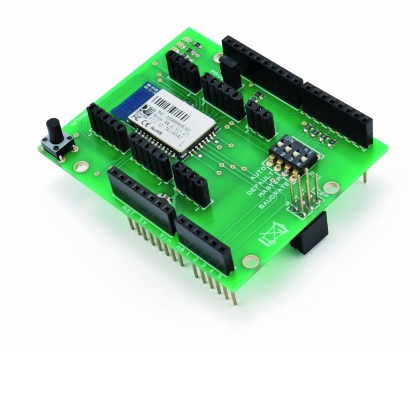
Our project is based on a shield carrying a RN-42 Bluetooth module.
Normally, by giving power to the module, we make it go directly into the data mode: in this mode, serial port pins are only used to exchange messages.
To enter the command mode, however, you can use a particular characters sequence, called escape sequence, which in our case is “$$$”. Therefore, by sending this sequence on the RX pin of the Bluetooth module, it responds with a confirmation string and waits for other commands. To return to data mode, there are other escape sequences that vary from module to module.
We can send these commands to the Bluetooth module by using the Arduino’s Serial, in our project we will do so.
The bluetooth RN-42 shield
The Arduino based RN-42 shield is suitable for all applications where you need to establish a Bluetooth connection with an Arduino board. Below you’ll find a brief description, starting from the available connectors, which are used to interface with the outside world (we don’t mention those granting the connection with Arduino).

The first is labeled RS232, whose connections are the following:
• 1 = CTS
• 2 = RTS
• 3 = TX
• 4 = RX
• 5 = GND
Such a connector is the serial interface through which data and commands are communicated. You can enter the command phase by sending the “$$$<cr>” escape sequence on the RX pin of the Bluetooth module via the local serial connection with the PC or directly from the Arduino. To get out of this phase and enter the data phase is necessary to send the sequence “—“.
During the data phase, and once a Bluetooth connection is established, what is sent to RX pin will be directed, by the radio interface, to the remote device, while on the TX pin we will find what is received from the remote device.
Usually we use only these three pin (TX, RX and GND), while CTS and RTS are used for flow control, but are still available.
In case you also want to use CTS and RTS you need to disconnect the PROG jumper. The CTS pin can also be used to “wake up” the Bluetooth module from the sleep phase (in which it consumes less than 2 mA) through the transition from logic state “0” to logic state “1.”
The second connector of the shield is the one dubbed IO and brings together three of the I/Os available on the RN-42. Its pinout is as follows:
• 1 = GPIO9
• 2 = GPIO10
• 3 = GPIO11
• 4 = GND
To read or drive these I/Os you need to enter the command mode (again, from a local serial port or directly from the Arduino). To control these I/O lines you must refer to the S*,<word> command, where word is a hexadecimal string of 16 bits whose most significant 8 bits represent the mask to determine the input and output pins, while the 8 least significant bits correspond to the pin values (1 is high, 0 is low).
Example:
S*,0202 enables GPIO9 as output and puts it to the value “1”
S*,0E00 puts all the GPIO in the strip to “0”
The GK command returns a hexadecimal string representing current pin values, these pins are also connected to the Arduino pins. In particular:
• GPIO9 is connected to A4
• GPIO10 is connected to A3
• GPIO11 is connected to A2
Let’s look at the AD connector now: its contacts are only analog inputs and they can be used by the Bluetooth module to acquire some information, such as the voltage level on the battery. The pin assignment of this connector is:
• AIO0
• AIO1
• GND
In this post we don’t really make use of the IO connector.
Instead Let’s look at the SPI connector, which pin are:
• 1 = S-MOSI
• 2 = S- SCLK
• 3 = S-MISO
• 4 = S-CS
• 5 = GND
This connector carries an SPI bus that could be used to write into the Flash memory internal to the RN-42 module in order to upgrade or replace the firmware; such connection is however not essential.
We also have a connector in the shield, dubbed PCM, whose pinout is as follows:
• 1 = GND
• 2 = P-OUT
• 3 = P-IN
• 4 = P-CLK
• 5 = P-CS
The PCM interface gives the possibility to send, a 64 kbps audio stream to another Bluetooth device. Again, this feature is not exploited in this application.
The last connector is the USB, which obviously carries a USB connection, and features this pinout:
• 1 = GND
• 2 = DP
• 3 = DM
• 4 = Vcc
However, this connection is possible only using the USB version of the RN-42 module (called RN-42-USB).
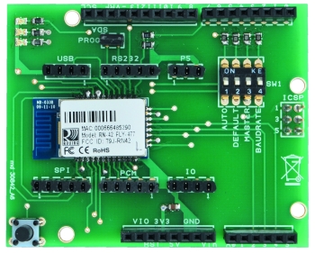

Once analyzed the connectors, let’s look at the other elements available in the shield, starting from the SW1 dip-switch, which can connect pins like GPIO3, GPIO4, GPIO 6 and GPIO7 from the Bluetooth module to the VCC pin (3.3V) though four resistors.
These pins are used to set certain modes of operation of the RN-42module. Moving the respective dip towards the word “ON” the pin of the module gets connected to Vcc and then at logic level 1, enabling its functionality. All these pins are interpreted at boot time, therefore if you change the state of the dips during the operation of the shield you will not see the desired effects.
Working modes can also be set by software, entering the control phase via the escape sequence “$$$”.
Below we describe the pins that go the dip-switch.
•AUTO: connected to GPIO3 pin of the Bluetooth module. If enabled, it allows automatic pairing with another Bluetooth device remotely, without therefore having to type the secret code (called “Passkey”). However, if the remote device is set to require authentication, a Passkey request will still be prompted before establishing a secure connection. The default Passkey is 1234, but can be changed, switching into command mode using the escape sequence “$$$”.
•DEFAULT. It’s connected to the GPIO4 pin of the module Bluetooth. It allows you to restore “factory” settings. It can be used when you issued conflicting commands. To reset the module, bring this dip to ON, before powering the shield; once powered you must switch the dip to OFF and then ON and do it again (ON/OFF). At each change of state you must wait at least about one second.
• MASTER. It’s connected to GPIO6 pin of the Bluetooth module. Note that, by default, the Bluetooth module behaves as a slave device: it can be detected by other Bluetooth devices and connect to them, but it is not able to start connections. Bringing the respective dip to ON, the module will work in MASTER mode. This means that it can’t be detected by other devices, but it will be able to make connections to particular remote devices that we have previously stored in the RN-42 Flash You can store devices through the SR command. The syntax is as follows:
SR,<address> (where <address> is the MAC address of the remote device you choose). If no is address stored, RN-42 will scan and connect to the first remote device found. Other Master mode behaviors are possible: these can be set only by software via the command SM, <x>, in which x represents the mode and can vary from 0 to 5. In particular, SM, 0 will make the module get back to slave mode.
• BAUDRATE. This dip is connected to GPIO7 pin of the Bluetooth module. Enabling it, it will force the communication speed for data and commands to 9,600 bps. Otherwise the desired speed should be written in the Flash using the command SU, <rate> (example: SU,57.6 will set 57,600 baud). By default, this value is equal to 115.200 baud. You can also set non-standard transfer rates.
Notice that you can also put two shields in point to point communication to allow two devices to communicate, by avoiding the use of a serial cable. In this case one of the two will have to act as a master and the other as slave. On both the AUTO dipswitch should be set so as not to require the authentication code.
Now let’s look at the LD1 status (red) LED connected to GPIO5 pin of the Bluetooth module: at the start, in slave mode, it flashes at a frequency of about 1 Hz to indicate that it is waiting for incoming connections.
Once entering the command mode it starts flashing at higher frequencies (around 10 Hz). Once connected with a remote device it stays on.
The second LED in the circuit (LD2, green) is connected to GPIO2 pin of the Bluetooth module: it stays always on and goes off only during a connection phase. The third LED (LD3, yellow) is connected to GPIO8 pin of the Bluetooth module and, during the connection phase, it shows data transmission (by means of a pulsation) both in one or the other direction..
Arduino code
At this point of the project we are ready to analyze the code for Arduino, which will receive the (already serialized) Bluetooth data from the external module and will translate them into actions, by changing LED bar colours. Bluetooth data are nothing more than earlier created messages (eg: the “R200\n” to bring the red component to a value of 200) that arrives to Arduino’s serial port on the RX pin.
Arduino will then pilot the LED bar through an RGB shield.
The module in question sports a default communication speed of 115,200 bps, but it can be configured with other values. It could even run at speeds that are usually not allowed for a standard RS232 serial PC ports, such as 1 Mbps. We actually set it up to work at 9600 bps.
Remember that using one of these external Bluetooth modules, we are going to use the full serial port of the Arduino board and we will miss a possible feedback that is useful in the test and debug phase to check the operating status of our code.
In this case we can always rely on an external serial library (SoftwareSerial) that allows us to emulate the serial port on any two Arduino pins and therefore to identify and solve potential issues.
Finally, still in the setup phase, we will put the Bluetooth module in command mode and then force it into the slave mode. Finally we’ll put it back into the data exchange phase.
Throughout the whole setup phase we kept all the three differently colored LEDs on (so the LED bar will be white), at the end, before moving to the infinite loop, we’ll turn off all the LEDs (through the digitalWrite() function) in order to point out the passage into the data phase. In Listing 5, you can see this part of the code. Now we will be able to control the brightness of the bar through our Android app: let’s see how. In the loop() function, Arduino will wait to receive all serial data and isolate strings that end with the ‘\n’ character through the getSerialLine() function. Once isolated, the single message will be parsed by getColorFromString() and getComponentFromString(), both created to extrapolate the information as the desired color component and intensity. Now we can drive the output pins with the system function analogWrite() that will set a PWM signal on the corresponding pin.
#include <SoftwareSerial.h>

#include <string.h>
#include <stdlib.h>
#include <stdio.h>
#include <ctype.h>
#include <avr/io.h>
#include <avr/interrupt.h>
#include <avr/pgmspace.h>

#include <EEPROM.h>

#define RED_LED    3
#define BLUE_LED   6
#define GREEN_LED  5

#define BOARD_LED  13

byte SerialIn;
bool _debug = false;

SoftwareSerial mySerialDbg(8, 9);

int _sequenceSize = 0;
bool _sequenceMode = false;

int _seqR[20];
int _seqG[20];
int _seqB[20];
int _seqT[20];
int _iSeq = 0;

int _currR = 0;
int _currG = 0;
int _currB = 0;
int _currT = 0;

int _lastR = 0;
int _lastG = 0;
int _lastB = 0;

void test3()
{
  while(true)
  {
    readColorAndTimeFromEeprom(0);
    //_currB =10;
    faderEffectFromTo(BLUE_LED, _lastB, _currB);
    _lastB = _currB;
    delay(3000);

    readColorAndTimeFromEeprom(4);
    //_currB =100;
    faderEffectFromTo(BLUE_LED, _lastB, _currB);
    _lastB = _currB;
    delay(3000);

    readColorAndTimeFromEeprom(8);
    //_currB =200;
    faderEffectFromTo(BLUE_LED, _lastB, _currB);
    _lastB = _currB;
    delay(3000);
  }
}

void test2()
{
  int addr  = 0;
  writeColorAndTimeOnEeprom(0, 0, 0, 10, 0);
  writeColorAndTimeOnEeprom(4, 0, 0, 100, 0);
  writeColorAndTimeOnEeprom(8, 0, 0, 200, 0);
}

void test1()
{
    int addr = 0;
     //for(int i = 0; i < 3; i++)
     while(true)
     {
       readColorAndTimeFromEeprom(addr);
       addr+=4;

       _currR =10;
       faderEffectFromTo(RED_LED, _lastR, _currR);
       _lastR = _currR;
       delay(3000);

        _currR =100;
       faderEffectFromTo(RED_LED, _lastR, _currR);
       _lastR = _currR;
       delay(3000);

        _currR =200;
       faderEffectFromTo(RED_LED, _lastR, _currR);
       _lastR = _currR;
       delay(3000);
     }
}

void setup()
{
  pinMode(RED_LED,   OUTPUT);
  pinMode(BLUE_LED,  OUTPUT);
  pinMode(GREEN_LED, OUTPUT);
  pinMode(BOARD_LED, OUTPUT);

  digitalWrite(GREEN_LED, HIGH);
  digitalWrite(BLUE_LED, HIGH);
  digitalWrite(RED_LED, HIGH);

  // Serial.begin(9600);  // mymodule bt
  Serial.begin(115200);  // rn42 bt

  mySerialDbg.begin(9600);
  delay(500);
  mySerialDbg.println("Test Serial");

  delay(1000);
  /*
  Serial.println("+++");
  delay(4000);

  Serial.println("at+btsrv=1");
  delay(2000);
  */
  lampLed(2);

  digitalWrite(GREEN_LED, LOW);
  digitalWrite(BLUE_LED, LOW);
  digitalWrite(RED_LED, LOW);

  //test1();  // ok

  //test2();
  //test3();  // ok

}

void lampLed(int nLamp)
{
  for(int i=0;i<nLamp;i++)
  {
      digitalWrite(BOARD_LED, HIGH);
      delay(500);

      digitalWrite(BOARD_LED, LOW);
      delay(500);

  }
}

String getSerialLine()
{
 String strReceived = "";
 //while(SerialIn != 13)
 while(SerialIn != '\n')
  {
    if (Serial.available() > 0)
    {
         SerialIn = Serial.read();
         char a = char(SerialIn);
         strReceived += a;
         if (_debug)
         {
           Serial.print(a);
         }

    }
  }

  SerialIn = 0;
  //strReceived +="r\n";
  return strReceived;

}

char getComponentFromString(String serialStr)
{
  char color = serialStr.charAt(0);

  return color;
}

int getColorFromString(String serialStr)
{
  String intStr = serialStr.substring(1,4);

  char* intChars = "000";
  intStr.toCharArray(intChars,4);

  int val = atoi(intChars);

  return val;
}

void getFullRgbAndTime()
{
  String strRec = "";
  strRec = getSerialLine();
  _currR = getColorFromString(strRec);

  strRec = getSerialLine();
  _currG = getColorFromString(strRec);

  strRec = getSerialLine();
  _currB = getColorFromString(strRec);

  strRec = getSerialLine();
  _currT = getColorFromString(strRec);

}

// change color with fade
void faderEffectFromTo(int pin, int lastColor, int currentColor)
{
  bool deltaPositive = true;
  int delta = (currentColor - lastColor);
  if (delta < 0)
  {
    deltaPositive = false;
    delta = -delta;
  }
  for(int i = 0; i < delta; i++)
  {
    if (deltaPositive == true)
    {
      lastColor++;
    }
    else
    {
      lastColor--;
    }
    analogWrite(pin, lastColor);
    delay(10);
  }
}

void writeColorAndTimeOnEeprom(int addr, byte r, byte g, byte b, byte t)
{
  EEPROM.write(addr+0, r); delay(50);
  EEPROM.write(addr+1, g); delay(50);
  EEPROM.write(addr+2, b); delay(50);
  EEPROM.write(addr+3, t); delay(50);
}

void readColorAndTimeFromEeprom(int addr)
{
  _currR = EEPROM.read(addr+0);
  _currG = EEPROM.read(addr+1);
  _currB = EEPROM.read(addr+2);
  _currT = EEPROM.read(addr+3);
}

void showSequenceInEeprom()
{
  int addr = 0;
  _sequenceSize = EEPROM.read(0);
  while(true)
  {
   addr = 1;
   for(int i = 0; i < _sequenceSize; i++)
   {
     readColorAndTimeFromEeprom(addr);
     addr+=4;

     faderEffectFromTo(RED_LED, _lastR, _currR);
     faderEffectFromTo(GREEN_LED, _lastG, _currG);
     faderEffectFromTo(BLUE_LED, _lastB, _currB);

     _lastR = _currR;
     _lastG = _currG;
     _lastB = _currB;

     int timeDel = _currT * 1000;
     delay(timeDel);
   }
 }
}

void loop()
{

   String strRec = getSerialLine();
   //String strRec = "ciao";

   digitalWrite(BOARD_LED, HIGH);

   Serial.println("Rec:" + strRec + "\n");

   char colComponent = getComponentFromString(strRec);

   int colValue = getColorFromString(strRec);

   if(colComponent == 'R')
   {
     analogWrite(RED_LED, colValue);
   }
   else if(colComponent == 'G')
   {
     analogWrite(GREEN_LED, colValue);
   }
   else if(colComponent == 'B')
   {
     analogWrite(BLUE_LED, colValue);
   }

   // sequence mode
   else if (colComponent == 'S')
   {
     _sequenceMode = true;
     _sequenceSize = colValue;

     // di default S=1
     getFullRgbAndTime();

     faderEffectFromTo(RED_LED, _lastR, _currR);
     faderEffectFromTo(GREEN_LED, _lastG, _currG);
     faderEffectFromTo(BLUE_LED, _lastB, _currB);

     _lastR = _currR;
     _lastG = _currG;
     _lastB = _currB;

     /*
     analogWrite(RED_LED, _currR);
     analogWrite(GREEN_LED, _currG);
     analogWrite(BLUE_LED, _currB);
     */

   }
   else if (colComponent == 'P')
   {
     showSequenceInEeprom();
   }
   else if (colComponent == 'M')
   {
     _sequenceSize = colValue;

     // read sequence for bluetooth android
     for(int i = 0; i < _sequenceSize; i++)
     {
       getFullRgbAndTime();
       _seqR[i] = _currR;
       _seqG[i] = _currG;
       _seqB[i] = _currB;
       _seqT[i] = _currT;
     }
     //analogWrite(BLUE_LED, 255);

     // store data in EEPROM

     EEPROM.write(0, _sequenceSize);
     int addr = 1;
     for(int i = 0; i < _sequenceSize; i++)
     {
       writeColorAndTimeOnEeprom(addr,_seqR[i],_seqG[i],_seqB[i],_seqT[i]);
       addr+=4;
       //delay(100);
     }
     //analogWrite(RED_LED, 255);

     // read data from EEPROM and show
     _sequenceSize = EEPROM.read(0);
     while(true)
     {
       addr = 1;
       for(int i = 0; i < _sequenceSize; i++)
       {
         readColorAndTimeFromEeprom(addr);
         addr+=4;

         faderEffectFromTo(RED_LED, _lastR, _currR);
         faderEffectFromTo(GREEN_LED, _lastG, _currG);
         faderEffectFromTo(BLUE_LED, _lastB, _currB);

         _lastR = _currR;
         _lastG = _currG;
         _lastB = _currB;

         int timeDel = _currT * 1000;
         delay(timeDel);
       }
     }
   }

   else
   {
    //  digitalWrite(GREEN_LED, LOW);
    //  digitalWrite(BLUE_LED, LOW);
    //  digitalWrite(RED_LED, LOW);
   }

}
Android code

Let’s start by opening a project on Eclipse and adding the functionalities that will allow us to manage the Bluetooth module of our device. We can do that with ease thanks to the APIs available in the ADT plugin (Android Development Toolkit), without the need of external libraries. You can simply add the following import in the main code before declaring the class:
import android.bluetooth.BluetoothAdapter;
import android.bluetooth.BluetoothDevice;
import android.bluetooth.BluetoothSocket;
You should also remember to add the request for the permission to use the smartphone’s Bluetooth in the AndroidManifest.xml file: you can do this thanks to the following lines of code:
<manifest>
…
<uses-permission android:name=”android.permission.BLUETOOTH” />
<uses-permission android:name=”android.permission.BLUETOOTH_ADMIN” />
…
</ manifest>
As said before, in a communication between two Bluetooth devices, one to act as a server and the other as a client. The server is started first and provides a “server socket” on which data will travel in both directions, in a half-duplex mode (ie not simultaneously). In order to communicate with the server, the client must first connect to the “server socket” (via connect() function) using the “MAC address” of the device that acts as a server.
In our project we use your smartphone as a client and the external Bluetooth module as a server. The MAC address is a six bytes unique identifier allocated to each network interface; knowing it, we are sure that the client will communicate only with the chosen server.
How do I know this address? Typically, the client performs a scan to verify the presence of other active remote devices, from which it gets the MAC addresses, so that the user can choose the servers he wants to connect to. Once you have chosen a MAC address, we will get the information of the remote device with the following lines of code:
mBluetoothAdapter = BluetoothAdapter.getDefaultAdapter();
BluetoothDevice device = mBluetoothAdapter.getRemoteDevice(serverAddress);
It’s worth noting that mBluetoothAdapter represents the local device obtained by the method getDefaultAdapter(); thanks to the getRemoteDevice() method – which accepts the MAC address of the remote device as a parameter – we get a BluetoothDevice from which we have information on its name, address and class. Finally, again from the remote device we can get the server socket (btSocket) as in the following line of code:
btSocket = device.createRfcommSocketToServiceRecord(MY_UUID);
and, to connect to the server we will use the line:
btSocket.connect();
For now we will deal with sending data in one direction only, ie from our smartphones to the Arduino (to which both the LED bar and the Bluetooth module are connected). This means that once we get connected to the server’s Bluetooth socket, we will use it only for writing, by sending data representing the color code from the interface, using the following lines of code:
outStream = btSocket.getOutputStream();
outStream.write(data);
At pressing the “On/Off” button we will have to initialize the Bluetooth module, making sure that our smartphone supports it and then that the module is enabled. In case of error, an error message will be displayed in a dialog box called MessageToast in the Android development environment.
Once connected, at each touch on the scroll bar a string with a message like: “R123\n” will be sent to the remote Bluetooth device: R indicates the red color (G for green, B for blue), while “123” is the value of the color component that can vary from 0 to 255 and with “\ n” wrap to determine the end of the message.
The message syntax is customizable. We could send strings of any kind: the important thing is to parse them consistently in the remote module (in our case Arduino will deal with this).
Notice that the API Log may have different levels depending on its relevance: Log.e() is used to identify an error message, Log.v() a simple informational message and Log.w() is for warnings. This diversity is reflected with different colors in LogCat (Android monitor).
The TAG, however, is always a text string and is used to differentiate the log messages so you can filter and analyze them without mixing them.
Moreover LogCat is active even without launching the application in debug mode simply plug the USB cable and enable debug mode on the Android device.
All functions for the management of the Bluetooth protocol are included in a new class (BtCore), contained in the file BtCore.java so they can be reused later in future applications that require the use of a Bluetooth module. You should, however, ensure that the java files in the same project (inside the src folder) have the same package in the header which in our case is ” package com.kiand.bt “
Android code: events
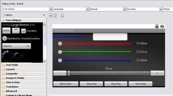
Now let’s see how to associate these actions to the graphical interface of our application: for example, let’s look at the _toggleOnOff button used to create the Bluetooth socket. First we define a ToggleButton object (also called widget): always remind to define the corresponding android.widget.ToggleButton import. In the OnCreate function() of the main Activity, we will associate that object to the resource that was previously generated in the file main.xml, using the findViewById() function:
_toggleOnOff =(ToggleButton)findViewById(R.id.toggleButtonOnOff);
At this point in time, we can change the _toggleOnOff button properties at will, for example by changing the wording (using the setText ()method) or the color (using setBackgroundColor()); we can then associate the (callback) function that will be called when the button is clicked. In fact, it will not pass exactly this function, but an interface class view.OnClickListener that already contains some methods including the onClick(), that we can fill as we wish. Usually this class is created directly (with the new operator) in parameter passing.
ToggleButton allows two states: we’re going to verify in which of the two states it is (either on or off) thanks to its onClick()method and we will act accordingly going to create the socket communication. By clicking a second time, we will close the Bluetooth socket.
The thing is easier for the buttons that we placed on the sides of the single progress bars to fine-tune the brightness.
The function to set the click callback is always the setOnClickListener(); in the onClick() function we’ll increase (for the + button) the value by updating the scroll bar via the setProgress() method and by changing the value of the _textViewG text string, via the setText() method. Of course, at the end, we’ll send the value reached to the Arduino board by using the sendMessageBluetooth() function, that will write the message (for example, the string “G234 \ n”) on the communication socket.
For the event related the scrollbars scrolling via touch, we will use a different method: while for the buttons all the code was within the onCreate() method of the activity, which is performed only the first time, in the case of the progress bar will use the method OnProgressChanged(). In any case in the onCreate() body will be necessary, first of all, to associate the seekBar object to the corresponding resource and set the callback to itself. In this way, each time that we will touch one of the three scroll bars the onProgressChanged() declared directly in activity will be called (note that it was necessary to implement a SeekBar.OnSeekBarChangeListener to be able to use it within the class itself).
In particular, the callback OnProgressChanged() sports three parameters that, at the time of the scrollbar touch, will be filled with the appropriate values in order to detect which of the three scroll bars (seekBar) has been moved and by which offset (progress).
The first value will be compared with each of the resources defined in the main.xml file (thanks to the method getId ()) while the second will be sent as a string to Android. Finally, the third one will be True or False depending on whether the movement has been generated by the user or not: in our case tough it will not be taken into account.
At this point in time our Android app has everything you need to control an external hardware platform, which, of course, shall be equipped with a Bluetooth module. The remote board (in our case an Arduino) will be in charge to catch the serialized messages and interpret them to trigger the related features (in our case, controlling the LEDs).
Download Code
![]()

Can this (or something similar) work for iPhone?
I’ve been waiting for someone to post a nice simple to follow tutorial on this – thanks very much
[…] For diagram see our previous post. […]
[…] Here’s an application to control the brightness of an RGB LED strip wirelessly (via Bluetooth) using a smartphone. The whole project is presented in a dedicated Bluetooth shield for Arduino and a RGB shield. […]
i really do like this project i am a student and i have a telecom project to present can you please help me i need some explanation about it please
Hi, we developed some projects with this shield
http://www.open-electronics.org/tag/bluetooth/
[…] Roving Networks RN-42, module. You can find the complete description of this module in a previous post here on this […]
You can buy Bluetooth 4.0 shields, arduino, usb adapter here: http://www.elecfreaks.com/store/products_new.html
Sorry my english. I wanted to ask, can you use a device to turn it on and off depending on the amount of light,(similar to This ) linking it to this project?