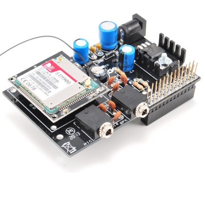

Today we present an expansion shield for Raspberry Pi to control the very effective GSM/GPRS SIM900 and SIM908 (with GPS) modules: in this way it is possible to extend the functionality of Raspberry Pi for mobile applications (eg: remote control) and, by employing the SIM908 module, even the GPS functionality. Even if we will describe the procedure to connect a Raspberry Pi, the same goes for all GNU / Linux equipped with a serial port.
We already created very similar expansion shields for Arduino that you can see here and buy on our store.
These Raspberry Pi shields are designed to be stacked on each other and be able to manage several tasks simultaneously: in this way so you can incorporate different “services” in one integrated solution. It may be the case of a home automation system, equipped with sensors and actuators, which uses the LCD for activation and deactivation, needing to add a remote interface via the GSM or TCP/IP networks.
In addition to this can you can add safety services for the elderly, that can be activated either locally or remotely, with voice or SMS capabilities to contact predefined numbers. We can even develop automated doors opening and associated with face recognition, or movement tracking: all these apps can send the same images in case of suspicious activities. The only limit is your imagination and the ability to design and implement applications. Applications of this complexity exceed the capacity of microcontrollers, although these can be used in the management of sensors and peripheral devices.
Back on the ground, clearly the different shields must not use the same pins, power aside, so as to avoid conflicts that cannot be managed via software. In the GSM/GPRS & GPS shield we used the GPIO pins connected to the serial port and two additional I/O pins for power (on/off) and SIM9XX module reset.
The Diagram
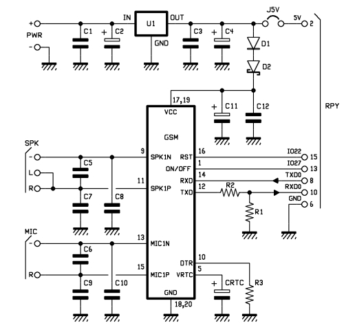
The GSM shield diagram aims to provide support for both SIM900 and SIM908 modules, to provide an autonomous power supply to the GSM module, to export the microphone input and audio output on two dedicated jacks and to connect properly the pins of the GPIO connector to those of the GSM modules.
Let’s start with the power supply circuit: it’s made by the U1 regulator, the 7805 integrated circuit and the network of the filter capacitors for voltage stabilization (C1, C2, C3 and C4). Through the D1 diode and the D2 zener to the positive voltage is brought to the VCC pin of the SIM9XX module.
Through the J5V bridge is also possible to supply the Raspberry Pi from the same source of the shield. It’s possible to connect to the PWR connector a power supply that delivers a continuous tension between 7 and 12 volts. The ON/OFF pin of the SIM9XX is connected to pin 13 of the Raspberry Pi GPIO (GPIO27) for switching on and off the module programmatically.
The RST reset pin of the SIM module is connected to pin 15 of Raspberry PI (GPIO22), again to allow to control it programmatically. The serial connection is attached on pin 8 (TXD) and 10 (RXD) of the Raspberry Pi. On the input line RDX voltage level to 3.3 V required by Raspberry Pi is realized by the voltage divider consisting of R1 and R2. No voltage adaptation is required in the opposite direction as the 3.3 V output from Raspberry Pi are compatible with the input of the SIM9XX modules. The DTR is constantly kept at a low level through the R3 resistor. The pin for power buffer of the Real-Time Clock (VRTC) is connected to the CRTC capacitor. Finally, the mike input line and the audio output are connected to the respective MIC and SPK connectors each with its network of filter capacitors, C6, C9 and C10 for MIC and C5, C7 and C8 for SPK.
Practical Use of the shield
As the first operation we should mount one of the GSM compatible modules on the shield and then assemble the shield to the Raspberry Pi, making sure that the bottom of the shield don’t touch the USB or Ethernet connectors. In case, just protect the connectors themselves with tape. Connect the peripherals to the shield and power the Raspberry Pi in the usual way.
By using GNU/Linux we can create applications that perform many functions, sharing resources such as the GSM shield. For example we could write an application that monitors external events such as an incoming voice call or SMS message, and is also able to react to internal events such as the activation of a given I/O and accordingly perform voice calls, send mass or individual SMS, send files (such as images), or emails etc… In the meantime, you may want to add geo referenced information thanks the GPS available on the board.
To perform all these functionalities you’ll need to design a modular architecture that can share resources without creating conflicts. An architecture consisting of server modules that interface and control resources and specialized modules providing the described functionalities and that can be recalled and executed when specific conditions are met. This will require communication services between the requestors (programs) and server modules, which can satisfy them according to a logic that ensures the priorities and avoid conflicts. To do this you need to delve down to the details of the functional requirements of the application and that’s the reason why, before going deep in the design of client/server apps, we propose you a in mode that allows an agile experience of the board. This mode allows you to use programs written for Arduino, with little modifications, so to familiarize with the shield in a more immediate manner. This mode will use the arduPi library made by Libelium Comunicaciones SL Distribuidas, available under the GNU General Public License and available from CookingHacks.
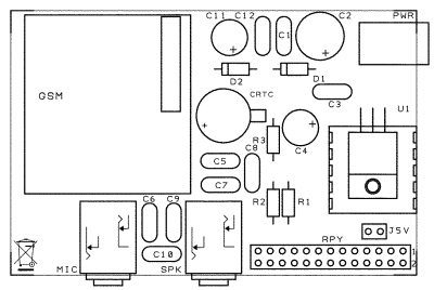
BOM
R1: 5,6 kohm
R2: 3,3 kohm
R3: 4,7 kohm
C1: 100 nF
C2: 470 µF 25 VL
C3: 100 nF
C4: 470 µF 16 VL
C5: 47 pF
C6: 47 pF
C7: 47 pF
C8: 47 pF
C9: 47 pF
C10: 47 nF
C11: 470 µF 16 VL
C12: 100 nF
U1: 7805
D1: 1N4007
D2: 1N5819
CRTC: 0,1F low profile
Send an SMS the Arduino style

The arduPi library can be installed by simply downloading http://www.cooking-hacks.com/skin/frontend/default/cooking/images/catalog/documentation/raspberry_arduino_shield/arduPi_1-5.tar.gz, and extracting the content in the /home. After that, just rename the folder as ArduPi and, for the sake of simplicity, put the programs we’re going to realize in the very same folder.
Before to compile the library open arduPi.cpp program and, if different, replace line 64 with the reference to the existing serial port with the line:
serialPort=”/dev/ttyAMA0″;
Now we go into the ArduPi folder with the command
cd /home/ArduPi
and compile the library with the command:
g++ -c arduPi.cpp -o arduPi.o
As for what regards the programs, we propose three modules. Two of them allow you to turn on and off the GSM module and will be very useful in the future. The third allows you to send a text message to a cell phone. To turn on the module you’ll need to raise the GPIO27 pin level for two seconds and then take it back to the low level, same procedure should be used to turn it off once on. To reset just raise and keep pin GPIO22 high half second (then putting it back to low). The programs are freely downloadable from www.elettronicain.it website.
First of all, to be able to use the serial port, we need to make a change to the boot process and disable the serial console, which otherwise would keep the serial port busy.
Disabling the serial console
Almost all GNU/Linux systems activate, when booting, the console feature, ie: the possibility to connect a terminal with the serial line – real or virtual – to manage the entire system via this communication interface. A reminder of the times in which we used to connected to computers thanks to modems using the phone line. To disable the console we use WinSCP, going to the “boot” folder with the command:
cd /boot
and opening, with a double click, the file /boot/cmdline.txt
and eliminate, paying attention, the following parameters:
console=ttyAMA0,115200 kgdboc=ttyAMA0,115200
and save the file.

Examples programs (turning on the module and sending SMS)
This code features the logic for module activation. As a first consideration you can see that the programs perform a single sequenceof instructions, in contrast to Arduino programs which work in a loop(). This allows you to use the individual programs as modules of a higher level application.
The activation process of the GSM module involves the following steps:
-
Control, by sending to the serial port an “AT” command to verify that the module is not is booted
-
In case of a negative reply (sending an AT command you should get the string “OK”), as a further check, the reset procedure is performed with a second AT command
-
In case of further negative response the ignition procedure is performed which consists in bringing the GPIO27 pin at high level for two seconds.
The purpose of the preliminary checks is due to the fact that switching on and off works with the same process, then if you run the program without the tests, if the GSM module is already on, it will switch off.
/*

*  GSMIgnition

*/

//Include ArduPi library

#include "arduPi.h"

int resetModulePin = 9;

int onModulePin = 8;

void switchModuleOn(){

   digitalWrite(onModulePin,HIGH);

   delay(2000);

   digitalWrite(onModulePin,LOW);

}

void resetModule(){

   digitalWrite(resetModulePin,HIGH);

   delay(500);

   digitalWrite(resetModulePin,LOW);

   delay(100);

}

int main (){

   Serial.begin(115200);

   delay(2000);

   pinMode(resetModulePin, OUTPUT);

   pinMode(onModulePin, OUTPUT);

   Serial.flush();

   printf ("zero\n");

   Serial.print("AT");

   delay(1000);

   if (Serial.available()==0)

      {

      printf ("uno\n");

      resetModule();

      delay(2000);

      }

   Serial.print("AT");

   delay(1000);

   if (Serial.available()==0)

      {

      printf ("due\n");

      switchModuleOn();

      }

return (0);

}
To compile the program using the command:
g++ -lrt -lpthread GSMIgnition .cpp arduPi.o -o GSMIgnition
To run the program, after moving to the ArduPi folder (cd /home/ArduPi)
you type:
./GSMIgnition
We can follow the steps to turn on the GSM module by observing the green LED: when turning on it stays on for about two seconds, then it goes off and starts flashing at intervals of about half a second, a sign that the module is searching for the GSM network. When the network is attached, the LED flashes at a much lower rate, about one flash per second.
This code shows the program to turn off the module, which expresses a very similar logic to the previous one:
-
Control, by sending the “AT” command on the a serial interface, that the module is not already off,
-
if not, as a further test, the reset procedure is performed by sending a second “AT” command
-
In case of a positive response the shutdown procedure is performed which consists in bringing the GPIO27 pin at high level for two seconds.
/*

*  GSMOff

*/

//Include ArduPi library

#include "arduPi.h"

int resetModulePin = 9;

int onModulePin = 8;

void switchModuleOff(){

   digitalWrite(onModulePin,HIGH);

   delay(2000);

   digitalWrite(onModulePin,LOW);

}

void resetModule(){

   digitalWrite(resetModulePin,HIGH);

   delay(500);

   digitalWrite(resetModulePin,LOW);

   delay(100);

}

int main (){

   Serial.begin(115200);

   delay(2000);

   pinMode(resetModulePin, OUTPUT);

   pinMode(onModulePin, OUTPUT);

   Serial.flush();

   printf ("zero\n");

   Serial.print("AT");

   delay(1000);

   if (Serial.available()==0)

      {

      printf ("uno\n");

      resetModule();

      delay(2000);

      }

   Serial.print("AT");

   delay(1000);

   if (Serial.available()>0)

      {

      printf ("due\n");

      switchModuleOff();                 //

      }

return (0);

}
To compile the GSMOff program use the command:
g++ -lrt -lpthread GSMOff.cpp arduPi.o -o GSMOff
To run the program, always after going to the ArduPi folder, use thecommand:
./ GSMOff
Finally, In this code, you can see the program that allows you to send an SMS.
/*

*  GSMSms

*/

//Include ArduPi library

#include "arduPi.h"

int timesToSend = 1;        // the SMS number to be sent

int count = 0;

int ok = 0;

int numCar = 0;

char phone_number[]="3........9";     // SMS destination number

void setup(){

   Serial.begin(115200);                // UART baud rate

   delay(2000);

   Serial.println("AT+CMGF=1");         // sets the SMS mode to text

   delay(100);

}

void loop(){

   while (count < timesToSend){

       delay(1500);

       Serial.print("AT+CMGS=\"");     // send the SMS(s)

       Serial.print(phone_number);

       Serial.println("\"");

       while(Serial.read()!='>');

       Serial.print("Se arriva funziona");     // the SMS body

       delay(500);

       Serial.write(0x1A);       //sends ++

       Serial.write(0x0D);

       Serial.write(0x0A);

       delay(5000);

       count++;

   }

}

int main (){

setup();

while(1){

loop();

             if (count == timesToSend)

             {

             break;

             }

}

return (0);

}
-
The variable phone_number[] contains the phone number to call,
-
AT + CMGF = 1 sets the SMS mode to Text,
-
AT + CMGS = sends the SMS messages set in the next instruction,
-
Finally, sends the “++” characters to end the call.
To compile the program you’ll type the command:
g++ -lrt -lpthread GSMSms.cpp arduPi.o -o GSMSms
and to run the program, as usual:
./GSMSms
Before to run the program you’ll need to run the GSM module activation routine, to make sure that the module is actually up and running. When you’ll go on in developing the control application, it should manage the correct sequence of calls, checks and the management of abnormal conditions. In Figure 5 you can see the status of the folder after writing and compiling your programs. In Figure 6 you can see the sequence of commands to compile and run the GSM module activation, SMS sending module deactivation. Finally, in Figure 7 you can see the actual SMS reception on the phone.
Store
The kit of GSM/GPRS & GPS Expansion Shield for Raspberry Pi is available in the store.
Remember you have to add the GSM module.

[…] A GSM/GPRS & GPS Expansion Shield for Raspberry PiPosted 7 days ago […]
You will have the pcb in pdf?
We’ll sell also the only PCB ;-)
[…] How to use the shield and write the program to build an SMS application is here. […]
[…] Step-by-step tutorial that shows you how to add GSM, GPRS and GPS functionality to Raspberry Pi: A GSM/GPRS & GPS Expansion Shield for Raspberry Pi; […]
[…] system which send a push notification when someone enters in a room. Inductive Proximity Sensor. A GSM/GPRS & GPS Expansion Shield for Raspberry Pi. Today we present an expansion shield for Raspberry Pi to control the very effective GSM/GPRS […]
Hi there,
I want to use this expansion shield for a project with my Raspberry Pi 2. Unfortunately I don’t know very much about electronics so I hope you can help me, because I really want to do this project using your components, the motivation to learn is there. The thing is I want to assure power supply using this USV:
http://piups.net/plus/#features
It says the Pin 3 and Pin 5 of the GPIO of the Raspberry will be used, if I consider plugging the USV onto my Raspberry. My question is can I stack the USV and your GSM/GPS shield up? Are the aforementioned pins also used by GSM/GPS and if so is there a possibility to get both shields to work?
Kind regards your time and help is much appreciated!
Jack
I forgot…USV is the German term for the more known English term UPS (Uninterrupted Power Supply)
Where can I buy this shield? Is it compatible with Raspi3?
Now a long time passed, I found out it is totally possible, there is no conflict with the USV shield and this expansion shield.
Cheers,
Jack
Is this compatible with the Raspberry Pi 2 Model B?
yes use the same pins
hello,
It is a GSM/GPRS & GPS Expansion Shield for Raspberry Pi. But the source code is for a arduino. could you explain to me?
Best regards
Is this compatible with the Raspberry Pi 3?
Yes of course
onModulePin = 8; doesn’t work for raspberry pi 3.It should be linked with GPIO27(Pin 13), but it is not. Anyone knows anything about this ?
Can the raspberry alone power the shield? Or do I need a second power converter?
[…] A GSM/GPRS & GPS Expansion Shield for Raspberry Pi – Today we present an expansion shield for Raspberry Pi to control the very effective GSM/GPRS SIM900 and SIM908 (with GPS) modules: in this way it is possible to … […]
onModulePin = 8; doesn’t work for raspberry pi 3.It should be linked with GPIO27(Pin 13), but it is not. Do you know about this problem?
The module is just starting the GPS but the GSM does not start, I am using Raspberry pi3. Could someone help me. Thanks.
Im trying to use this with a rev 1 B pi. The GSMIgnition seems to work fine but if i try to use the GSMsms. It never sends the sms text. Anyone get anywhere with this?
3rearguard