

No microcontrollers, just traditional and essential electronics for a light decoration you can hang anywhere, for a light effect very similar to the decorative lights on the Christmas tree…
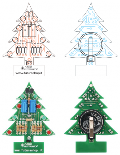
We have seen all kinds of Christmas decorations, especially when it comes to the Christmas tree: static and animated, passive and blinking, shaped as the globe, a bell, a star, a gift, a bow and so much more. But the one we have designed and propose in this article is even more original, because, although it has some lights that turn on, it is a small Christmas tree in its own right that you can hang anywhere. That’s right, a miniature tree with built-in lights that you can hang on the branches of your traditional Christmas tree, but which can also be hang to banners and any other decoration, since it is small and lightweight.
Our small tree is composed of a fir-shaped printed circuit with a base, and on its extremities we can find eight LEDs, half of which red and the other half green; everything is powered by a 3 V button cell battery, type CR2032; once powered on, i.e. when we insert the battery and close the dedicated jumper on the rear side, the LEDs start blinking alternatively and light on in order to execute a zigzag animation.
Let’s not waste any more time and see what this is all about, by analyzing the circuit, which is really really simple, as you can see from the circuit diagram.
Circuit diagram
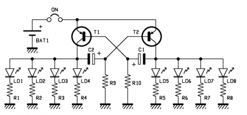
In order to light two LEDs on two groups thereof, all we need is a generator of two rectangular signals in phase opposition, which is known as astable multivibrator in its most essential form. The multivibrator is the heart of our project and can turn the LEDs on by itself; all it needs is a low voltage, direct power, which is provided in our case by a button cell battery through the jumper labeled ON, allowing to apply and remove voltage in order to activate or deactivate the light decoration.
Let’s take a brief look at the circuit diagram, where the astable multivibrator is the circuit portion composed of BJTs T1 and T2, both PNP type, surrounded by the R9-R10 resistors in the C1 and C2 capacitors; the LED-resistor dipoles on the sides are the collector’s load of the transistor, which therefore acts at the same time as switching element for the multi-vibrator and LED drivers. This allows to make everything really simple.
Our circuit, and therefore the astable, is a rectangular signal generator; the signal is created since the circuit cannot keep a stable state and therefore its transistors are continually and alternatively switching, so that T1 and T2 always show opposite voltage levels on their respective collectors.
This phenomenon starts when the circuit is powered on, and, although both capacitors are empty, the transistor with the lowest threshold voltage starts conducting first and blocks the other one, until the capacitor connected to its base is charged. The circuit can’t work because there are constructive differences between the components and particularly between the BJTs, even if they are of the same kind; in case of ideal transistors, the circuit couldn’t work. In fact, the so-called “characteristics deviation”, i.e. the differences between the parameters of BJTs coming from the same production lot, creates a difference in threshold voltage and in the hFE, and these differences are such that, in the circuit, one transistor starts conducting before the other one. Another element of difference is in the tolerances of R9 and R10 resistors and C1 and C2 capacitors.
| R1: | 180 ohm |
| R2: | 180 ohm |
| R3: | 180 ohm |
| R4: | 180 ohm |
| R5: | 180 ohm |
| R6: | 180 ohm |
| R7: | 180 ohm |
| R8: | 180 ohm |
| R9: | 47 kohm |
| R10: | 47 kohm |
| C1: | 22 µF 63 VL |
| C2: | 22 µF 63 VL |
| T1: | BC557 |
| T2: | BC557 |
| LD1: | LED 3 mm green |
| LD2: | LED 3 mm red |
| LD3: | LED 3 mm red |
| LD4: | LED 3 mm green |
| LD5: | LED 3 mm green |
| LD6: | LED 3 mm red |
| LD7: | LED 3 mm green |
| LD8: | LED 3 mm red |
In order to understand how the astable works, let’s suppose that when we supply power, T1 starts conducting, and its collector goes to logic level high (power positive) and positively short-circuits the C2 capacitor; this electrolytic capacitor, not charged at first, sends out an impulse to T2’s base which keeps the PNP in interdiction.
Then, C2 starts charging up through R9 with positive polarity on the -, up to the point when T2’s base shows a negative voltage that is strong enough to put that transistor in saturation; now, it’s T2’s collector that goes high and discharge C1, providing an high impulse to T1’s base that puts that transistor in interdiction, therefore its collector stops conducting.
Now, C2 starts charging up with positive voltage on the terminal + and after a while, it brings T1’s base to a voltage that causes it to go into interdiction once again, so that its collector goes back to 0 V and immediately discharges C1, which in turn provides a low level impulse to T1’s base, putting it back into conduction. The cycle repeats itself as long as the circuit is powered and causes the creation of two rectangular waves in phase opposition on T1 and T2.
These voltages are enough to polarize and therefore light on the LED groups placed between collectors and ground, which are each composed of four LEDs, half green and half red; this kind of connection and the particular disposition on the printed circuit, allow to light the green LEDs of one side of the tree and the red LEDs of the opposite side and vice versa. The resistors have been calculated so that the red LEDs can be powered on using a current which is a compromise between battery life and brightness; this current is just a hair over 5 mA for the red LEDs and something less for the green ones, since all the resistors are 180 Ω and voltage falls on the LEDs are different between red LEDs (1.8 V typical) and green LEDs (2.1 V typical).
From OpenStore
