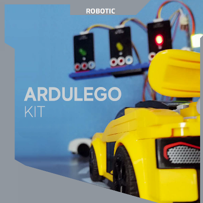
Lots of components to make applications that can be programmed with Arduino and assembled like LEGO bricks.
How many times did you dream of building something with LEGO bricks when you were a child and see it moving, animated, perhaps integrating a certain amount of programmable electronics to keep up with the times? Well, thanks to ARDULEGOKIT, that dream can come true, because it is a set of LEGO-compatible blocks equipped with electronic components of various kinds, to create animated constructions. But the fun doesn’t end there, because the electronic elements contained in the ARDULEGOKIT package can be managed through Arduino (an Arduino Uno board to be exact), which makes the world of LEGO electronics even more interesting and accessible to those who dabble in electronics and those who use it for educational purposes.
A LOOK INSIDE THE KIT
Designing, building and having fun: this is the aim of the ARDULEGOKIT, available from Open Electronics (www.open-electronics.org) in a practical toolbox, containing, divided into small boxes, a large number of modules designed to be placed on LEGO bricks and used to create robotics applications and exercises.
It comes with a handout, and a tutorial manual, which will help you experiment with sketches to test the various modules with the Arduino Uno and the Sensor Shield (we will explain what this is short).
But what are the features of the ARDULEGOKIT and how are its components made? Well, the first one is that each electronic component is not the classic single component to be soldered, but it is soldered on a printed circuit board, therefore supplied in the form of a breakout board, thus allowing those who use this kit not to have to deal with soldering and to realise with extreme practicality and simplicity the connections required by the circuit they are going to design.
As an example, if we wanted to connect an LED to the Arduino, we would normally have to calculate its falling resistance (R) using the formula:
R = (V – Vs)/ I
where I is the current absorbed by the LED, Vs the direct voltage of polarisation of the LED and V the supply voltage from which we start; but in the case of the LED module supplied in the kit, we can connect it directly to Arduino without worrying about protections. Furthermore, each module with an electronic component onboard has three or more holes that fit perfectly with the LEGO bricks, so in addition to the easy electrical connection, there is the advantage of perfect mechanical integration with the LEGO environment and also the physical support. With a view to handling the Arduino, the kit includes a shield specifically designed to connect the various components. This shield sits on top of the Arduino Uno and extends the ports present, the number of digital (14) and analogue (6) pins remains the same, but each of them is provided with two more pins, one for GND and one for VCC (5V), this shield also has pins dedicated to the use of certain sensors such as 6 pins dedicated to the SD card interface, 4 pins for the SR-HC04 ultrasonic sensor, 6 pins for the HC-05 and HC-06 Bluetooth modules, 6 pins for the APC220 wireless interface, 4 pins for the I²C-Bus interface, 4 pins for the serial communication interface, 6 pins for the serial LCD display and 14 pins for the parallel LCD display.
The connection between the Arduino and the PC for programming is made via a USB cable supplied in the kit itself, while the connection between the microcontroller and the various modules is made via three, four or five-wire Dupont cables, depending on the module being used. It is important to bear in mind that the three-wire Dupont cables have different colours according to the pin to be used: GND=black, VCC=red, Signal=yellow, while the four and five-wire Dupont cables do not have different colours.
Using the various modules is very simple even for those who have never worked with electronics since there is no need to size other components, but at the same time, it is also very interesting for those who are more experienced in this field since components are not included in the kit, such as those illustrated above, can also be connected to the shield.
We will now look at and describe a couple of practical applications designed to familiarise you with the various modules contained in the ARDULEGOKIT.
A TRAFFIC LIGHT FOR OUR BRICK CITY
Who among us has never tried to create their own city with LEGO? There are those who build normal cities, like the ones we live in, those who build cities set in different historical eras, those who have them colonised by aliens or those who build super-technological cities with Futurama-style flying cars. But in addition to people and vehicles, don’t we want to have a traffic light? Perhaps animated and working, with LEDs that actually light up, performing the light sequence of a real traffic light like the ones we find on the streets? And with a call button for pedestrians?
If this is what we want, ARDULEGOKIT can help us make it a reality.
The material required to make this application is as follows:
- red, green and yellow and RGB LED modules;
- touch sensor;
- Arduino One.
Once you’ve got all the tools you need, you can build your own traffic light. It can be tall, low, crooked, hung on a wire, you name it, and use the LED modules in the kit as light. We also use the RGB LED to create a pedestrian call light controlled by a touch sensor.
Once the traffic light is built, we connect the LED modules and the touch sensor with three-wire Dupont cables: GND, VCC and Signal (one of the D0-D13 digital pins) while we connect the RGB LED with a four-wire Dupont cable: VCC and R G B (three different D0-D13 digital pins are needed).
The pins intended for the LEDs will be outputs, while the touch sensor will be an input; in fact, the latter works practically like a button, so it releases a high value if it is pressed and a low value if it is not pressed. The sensor in question is based on the detection of the electrical capacity of a capacitor: the circle we see when we look at it constitutes an armature of the virtual capacitor and when a body capable of conducting (in our case a finger) approaches, it forms the second armature. At this point, a transfer of electrical charge occurs due to the electric field created between these armatures, and the resulting subtraction of charge is detected by the electronics built into the sensor.
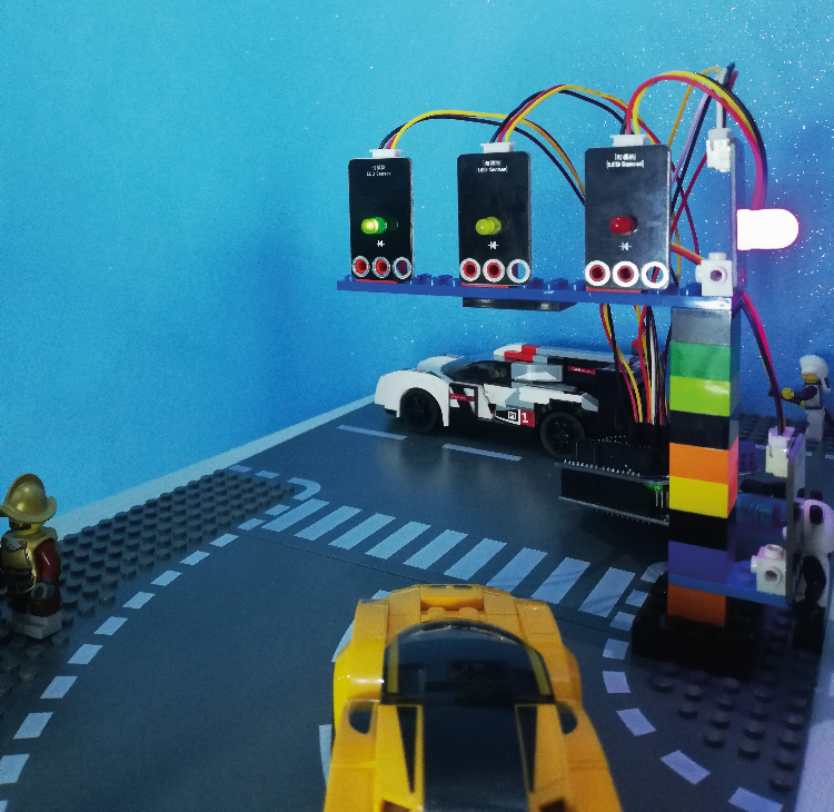
Fig. 1 shows our traffic light assembled and placed on a LEGO model.
Well, having said that, we have explained the electronics and we can now dedicate ourselves to the software aspect, with the application code shown in Listing 1: in it, we see that the traffic light LEDs are managed by digital pins 11 (green) 12 (yellow) and 13 (red), while digital pins 8 (blue) 9 (green) and 10 (red) are assigned to drive the RGB LED. The touch sensor is read via digital I/O 7, which has been initialised as an input.
Listing 1
#define ledAutoR 13 //red LED module
#define ledAutoG 12 //yellow LED module
#define ledAutoV 11 //green LED module
#define ledPedoniR 10 //RGB red
#define ledPedoniG 9 //RGB green
#define ledPedoniB 8 //RGB blue connected just to avoid having a cable around
#define touch 7 //sensor
//waiting time
int intervallo=5000;
int value; //variable for reading
void chiamata();
void setup() {
// definizione input output
pinMode(ledAutoR, OUTPUT);
pinMode(ledAutoG, OUTPUT);
pinMode(ledAutoV, OUTPUT);
pinMode(ledPedoniR, OUTPUT);
pinMode(ledPedoniG, OUTPUT);
pinMode(ledPedoniB, OUTPUT);
pinMode(touch, INPUT);
}
void loop() {
value=digitalRead(touch);
if(value==HIGH){ //traffic light call
chiamata();
}
//red car led green pedestrian led
digitalWrite(ledAutoR, HIGH);
digitalWrite(ledAutoG, LOW);
digitalWrite(ledAutoV, LOW);
digitalWrite(ledPedoniR, LOW);
digitalWrite(ledPedoniG, HIGH);
digitalWrite(ledPedoniB, LOW);
delay(intervallo);
//Yellow LED Car Green LED Pedestrian
digitalWrite(ledAutoR, L
A GARAGE FOR SORTING SUPERCARS
We don’t necessarily have to leave our supercar in the street, even if it is made of LEGO; for example, we can store it in a cosy garage. To make this garage more realistic, we can add some electronic signals to indicate to the mini-figures passing by in the model if and which car is about to leave its garage, in order to avoid unpleasant accidents!
A kind of active signposting that wouldn’t hurt in reality.
The material required for this exercise is as follows:
- LED module of your choice;
- buzzer with or without electronics;
- photo-resistance or ambient light sensor;
- Arduino One.
First of all, we have to build a garage suitable for our supercar(s). Once this is done, we will place the photoresistor inside the garage. The photoresistor is a variable resistor that reports a larger or smaller analogue value depending on the amount of light perceived, while the ambient light sensor works in the same way but is not a variable resistor. The brighter the environment, the closer the values are to zero; vice versa in the dark. The LED and the buzzer, on the other hand, we will place outside the garage.
As for the two light sensors, since they are analogue sensors, their Signal pin should be connected to one of the analogue ports of the Arduino Uno, while the buzzer and the LED are both assigned to digital outputs. Since they both work on the basis of light, it’s always best to test what they sense when the garage is open and when the garage is closed in order to find an approximate threshold value.
This can be done using the code below.
#define fotoresistenza A0

int valueF;

void setup() {

  pinMode(fotoresistenza, INPUT);

  Serial.begin(9600);

}

void loop(){

    valueF=analogRead(fotoresistenza);

    Serial.println(valueF);

}
The choice of the buzzer is subjective because on the market this component is found in various versions, capable of emitting sounds at different frequencies. But that’s not all, because there are buzzers with and without electronics: if we use a buzzer with electronics, we can also simply connect it to the power supply and it will start to sound thanks to a component in it that triggers the oscillation, whereas if we use a buzzer without electronics (which is a pure piezo pad) it must be driven with a one-way variable voltage, otherwise it will not emit any sound. In the case of use with Arduino, in the first case, digital output at high logic level is sufficient, while in the second case it is necessary to drive the buzzer with a PWM digital pin of Arduino Uno and activate it from software.
In this kit there are both types of buzzers: the one with electronics has a sticker on the top, while the one without electronics does not.
Once we have found the threshold value and decided which buzzer to use, we can concentrate on the final design. The LED and buzzer will remain off until the photoresistor detects a sufficient value greater than the indicated threshold value.
The firmware to be written to realise the application is shown in Listing 2.
In it we see that the acoustic signalling is done by digital pin 8, the switching on of the signalling LED that illuminates the road signal by pin 13 and the reading of the photoresistor is done by analogue line A0, which in this case acts as an input.
In the loop, we have the cyclical reading of the photoresistor status and the consequent management of the visual (LED) and acoustic (buzzer) signalling.
Listing 2
#define buzzer 8
#define led 13
#define fotoresistenza A0
int sensorValue = 0;
int soglia=150; //photoresistance threshold
void setup() {
// put your setup code here, to run once:
Serial.begin(9600);
pinMode( fotoresistenza, INPUT);
pinMode( led, OUTPUT);
pinMode( buzzer, OUTPUT);
}
void loop() {
// put your main code here, to run repeatedly:
sensorValue = analogRead(fotoresistenza);
Serial.println(sensorValue);
if(sensorValue>soglia){
digitalWrite(led, HIGH);
digitalWrite(buzzer, HIGH);
delay(100);
}
else{
digitalWrite(led,LOW);
noTone(buzzer);
}
}
SAFE DRAWER
We now move on to our third teaching application, which consists of making a “protected” drawer.
Run out of ideas about where to hide valuables? There’s no reason why you shouldn’t put them in a drawer made of LEGO, even better if it has a sophisticated burglar alarm system.
So let’s see what we need to make this application; the material required is:
ambient light sensor or photoresistor;
- LED;
- buzzer;
- IR receiver;
- IR remote control;
- button;
- Arduino One;
- 3V CR2025 battery (not included in the kit).
The operation of this “intelligent” drawer is, to say the least, simple but at the same time suggestive: the ambient light sensor or the photoresist, positioned at the top of the drawer, will detect when the drawer is opened; but the system is designed in such a way that in order not to trigger the alarm, it is first necessary to select the correct key using the remote control, in order to authenticate oneself.
If the button is the right one, the “intelligent” drawer will recognise us as the owner, otherwise, the buzzer will sound and the LED will flash. At the same time, a 16×2 display at the I²C-Bus interface will show either the message “welcome” or the message “to the thief” (Fig. 2) depending on whether the person opening the drawer has authenticated himself or not.
The 16×2 LCD (Liquid Crystal Display) (16 columns and 2 rows for writing) with I²C (Inter-Integrated Circuit, a protocol that allows signals to travel in parallel) interface is an alphanumeric display to show on screen writings, numbers or values that would normally be displayed on the Arduino serial monitor.
In this kit, the display is already soldered to the I²C interface. It has 4 pins: GND, VCC(5V), SDA (data) and SCL (clock signal) to be connected respectively to the pins dedicated to the I²C-Bus interface.
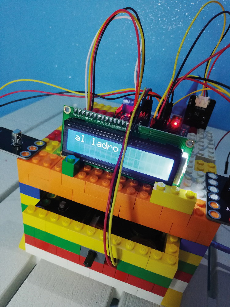
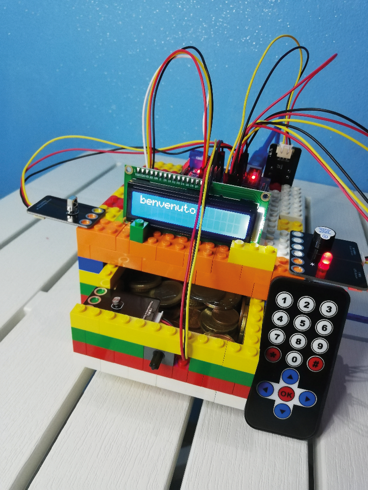
Fig. 2
Thanks to the SDA and SCL pins we can connect up to four displays in parallel, differentiating each device with a different address.
At the front of the LEGO brick drawer is a backlit LCD display, and at the rear, on the I²C interface, is a trimmer from which the brightness of the display can be adjusted.
To understand how it works, refer to the code in Listing 3.
Listing 3
//library required to use the display
#include <LiquidCrystal_I2C.h>
//lcd is the name of the display in this sketch
//0x27 is the display address
//16 is the number of columns (0-15)
//2 is the number of rows (0-1)
LiquidCrystal_I2C lcd (0x27, 16, 2);
void setup() {
lcd.init(); //initialises the display
lcd.backlight(); //initialises the backlight
}
void loop() {
//to move the display cursor
lcd.setCursor(colonna, riga);
//to write text I use ("")
lcd.print(“testo”);
//to write a variable I only use the ()
lcd.print(variabile);
}
The remote control uses infrared technology to communicate with the IR receiver module. The receiver has 3 pins: GND, VCC (5V) and Signal (digital pin D11), while the remote control has 10 numeric keys, 4 arrows, hash mark, asterisk and ok. Infrared transmission is at a high frequency (approximately 38 kHz) from the remote control, which emits a sequence of bits (0 and 1) representing the various buttons; this sequence is intercepted by the receiver which, via the program, knows which button it corresponds to.
The button has the task of making the program store the exact code, which is why it must be placed hidden.
Also, for this program (its code is shown in Listing 4) it is better to evaluate the exact threshold value of the photoresistor (read from analogue pin A0) contained in the light sensor. In the code we see first of all the inclusion of the library for the infrared sensor, which is read from pin D11; the LED is instead driven by Arduino Uno’s D13 and the buzzer by D8. D3 is used to read the button.
In the loop, the button is managed with its learning, as well as the update of the LCD display for which the LiquidCrystal_I2C.h library was included at the beginning. The reading of the light sensor to verify the opening of the drawer and the prior reception of the code of the alarm release button are also managed.
Listing 4
//library required for infrared control
#include <IRremote.h>
//library required for displya
#include <LiquidCrystal_I2C.h>
#define IR_RX 11 //pin del ricevitore IR
#define LED 13
#define button 3 //settings button
#define buzzer 8
#define luce A0
int soglia=150; //threshold value light
unsigned long tasto; //variable with the key code
IRrecv irrecv(IR_RX); //declaration iR
decode_results results; //conversion from bit to decimal
//lcd is the name of the display in this sketch
//0x27 is the display address
//16 is the number of columns (0-15)
//2 is the number of rows (0-1)
LiquidCrystal_I2C lcd (0x27, 16, 2);
void setup()
{
pinMode(luce, INPUT);
pinMode(LED, OUTPUT);
pinMode(button,INPUT);
pinMode(buzzer,OUTPUT);
irrecv.enableIRIn(); //IR activation
Serial.begin(9600);
lcd.init(); //initialises the display
lcd.backlight(); //initialise backlighting
}
int on = 0;
unsigned long last = millis();
void loop() {
Serial.println(tasto);
int buttonState = digitalRead(button);
delay(100);
if ( buttonState == HIGH) {
Serial.println(“Impostazioni...”);
if (irrecv.decode(&results) && millis() - last > 250){
tasto = results.value;
Serial.println(“Memorizzo il nuovo codice”);
Serial.println(tasto); //key is the variable where the correct key is stored
Serial.println(results.value);
last = millis();
irrecv.resume();
}
}
if (irrecv.decode(&results)){
if ((millis() - last > 250 && results.value==tasto )&&(analogRead(luce)>soglia)) {
//to move the display cursor
lcd.setCursor(0, 0);
//to write text I use ("")
lcd.print(“benvenuto”);
digitalWrite(buzzer, LOW);
}
else if ((millis() - last > 250 && results.value!=tasto )&&(analogRead(luce)>soglia)) {
digitalWrite(LED, HIGH);
digitalWrite(buzzer, HIGH);
lcd.clear();
lcd.setCursor(0, 0);
lcd.print(“al ladro”);
}
last = millis();
irrecv.resume();
}
}
THE INTELLIGENT VASE
And here we are at the last educational application that we will propose in this article and that concerns those who have a more or less “green” “thumb”. Nowadays LEGO bricks are used to make anything, so why not use them to build a pot for a plant? Perhaps with sensors applied to tell us when the little plant inside is “thirsty” and needs watering?
Well, if you want to do that and build this ‘smart’ pot, you need to use the following elements:
- soil moisture sensor;
- liquid level sensor;
- Red and green LEDs;
- Arduino One.
Perhaps we should use Lego Duplos to make a vase, to make life a little easier, but don’t worry about compatibility between the two ‘series’ of bricks, because the LEGO bricks fit perfectly into the Duplos.
The aim of this experiment is to monitor the health of a plant using two sensors.
The first is the one that measures soil moisture by detecting the volumetric water content, which is done by detecting the dielectric constant of the soil using capacitive technology. The measurement system uses a frequency of 70 MHz, which minimises interference due to salinity. The second sensor detects the level of water present, providing a corresponding voltage value on an analogue pin; it provides zero volts if it is not in contact with the water, but as it is immersed the conductivity increases and so do the output values.
The LEDs are used to indicate the current status of the plant. For both sensors, however, threshold values must be calculated, which are then imported into the final program; the routine for calculating the humidity using the liquid level sensor is as follows:
#define Lacqua A0

int valueL;

void setup() {

  pinMode(Lacqua, INPUT);

  Serial.begin(9600);

}

void loop(){

    valueL=analogRead(Lacqua);

    Serial.println(valueL);

}
Instead, the one for calculating the threshold value for the dry land condition is:
#define Hterra A0

int valueH;

void setup() {

  pinMode(Hterra, INPUT);

  Serial.begin(9600);

void loop(){

    valueH=analogRead(Hterra);

    Serial.println(valueH);

}
Once the appropriate measurements have been made, we can test the final program, which corresponds to the code shown in Listing 5.
Listing 5
#define Hterra A0
#define Lacqua A1
#define ledR 13
#define ledV 12
int sogliaTerra = 150;
int sogliaAcqua = 150;
int valueH, valueL;
void setup() {
// put your setup code here, to run once:
pinMode(Hterra, INPUT);
pinMode(Lacqua, INPUT);
pinMode(ledR, OUTPUT);
pinMode(ledV, OUTPUT);
}
void loop() {
// put your main code here, to run repeatedly:
valueH = analogRead(Hterra);
valueL = analogRead(Lacqua);
if((valueH>sogliaTerra)||(valueL>sogliaAcqua)){
digitalWrite(ledR, HIGH);
digitalWrite(ledV, LOW);
}
else{
digitalWrite(ledR, LOW);
digitalWrite(ledV, HIGH);
}
}
CONCLUSIONS
In this article, we have presented the ARDULEGOKIT, a set of electronic components in breakout board format designed to be applied to LEGO bricks and to be used in applications governed by electronic circuits managed by Arduino Uno through the interface provided by a specific shield.
These are four application examples to be considered as exercises in which we have tried to show you how to use as many circuit elements as possible, also explaining how to write firmware to implement the management through the Arduino Uno board.
Of course, on the basis of what has been explained, each of you can develop applications as you see fit.
Even before the appearance of educational sets such as the ARDULEGOKIT, it was difficult, to say the least, to limit your imagination when using LEGO bricks. Now, thanks to the possibilities of this kit, whether you are an expert or a beginner in the world of electronics and programming, you can finally say goodbye to the limits of your imagination and have fun with LEGO and its developments.
FROM OPENSTORE
