[bctt tweet=”A transceiver unit to broadcast audio MP3 files over Wi-Fi” username=”OpenElectronics”]
In this article, we want to propose you what can be considered as the natural evolution of project Ethernet Broadcaster; the goal is still the same, i.e. allowing broadcasting of music or customizable audio messages. Besides adapting to the ever-growing trend of a widespread Wi-Fi (for instance, we have Wi-Fi on all smartphones…). We wanted to create this new project in order to overcome physical barriers imposed by wired networks. As it was the case for the Ethernet Broadcaster, one circuit will act both as transmitter and receiving unit, in order to simplify the hardware.
The system will use the protocols defined by the IEEE 802.11 standard to create wireless connections and spread the sampled audio via RF. The circuit we propose is, therefore, a Wi-Fi Broadcaster and allows, when acting as the transmitter, to sample an analog audio signal and transmit the corresponding digital flow to another similar device or to any other digital player which is compatible with used standards (SHOUTcast and IceCast).
The circuit, set as the receiver, will reconstruct the analog signal previously digitalized. The Wi-Fi broadcaster is also compatible with ethernet broadcaster, therefore we can create both homogenous systems, i.e. exclusively made of Wi-Fi modules, and heterogeneous ones, composed of wireless modules and wired modules. In terms of solutions adopted, will have to choose whether to use a common network access point, in fact, in case we choose to only use Wi-Fi modules, we will be able to configure a unit in SoftAp mode and connect up to 4 modules (client) to the virtual access point, therefore creating a private network of just broadcaster units.
CIRCUIT DIAGRAM
Now, let’s take a look at the circuit diagram which is basically similar to the ethernet broadcaster. In fact, the main unit is still the PIC32MX695F512H microcontroller (U2), which is still the high-end representative from the 32MX Microchip family, having 512 kByte of program memory and 128 kByte RAM, besides, it has all the necessary hardware to interface with a USB 2.0 device. The microcontroller integrates standard peripherals such as Serial Peripheral Interface (SPI) used to communicate with chip U7 and module U4, Inter Integrated Circuit (I²C) to dialogue with the outside world through the connector J7 and the Universal Asynchronous Receiver-Transmitter (UART), also used to optionally communicate with U7 or with the outside environment through the J7.
Moving on with the description of the circuit, the second component in order of importance is U7: it’s a VS1063, which is a MP3 slave processor made by VLSI Solution, which we have already used in the past thanks to his excellent characteristics, such as the possibility to play or record audio streams coded in different formats, such as the widespread MPEG-1/2 Audio Layer 3 (MP3) and the royalty-free competitor Ogg Vorbis. The two main components U2 and U7 can communicate thanks to an SPI channel shared with U5; in particular, we have chosen SPI peripheral number 2 and four more digital lines: xCS, XDCS, RESET e DREQ. The first three lines are input signals for U7 and respectively corresponds to chip select (SPI mode) for the control section of the U7, to chip select for the data section and to the reset to synchronize the corridor and microcontroller when the system starts up. The last line, labeled DREQ, corresponds to one output of VS1063 and its purpose is to signal the host microcontroller (the one interfacing with VS1063) both space availability in its FIFO memory, and receiving new commands and new data.
On the same SPI bus there is the flash memory SST25VF032B labeled U5, which have a CMOS architecture and 2 MB memory, therefore it can host on the pages of the application and the jQuery library responsible for the webpages’ dynamism.
The integrated U5 is also controlled by two more signals generated by U2, WP and HOLD which allow, respectively, to block and momentarily stop the writing of new content inside it. On the other hand, channel 3 of the SPI bus is used to communicate at high priority with module U4, which is the Wi-Fi transceiver MRF24WG0MA.

As for the power section, the circuit has two Low Dropout regulators (LDO), hosted by the same package (SOT236) which is called U6 in the circuit diagram. The latter, labeled AP7312-1828, is an extremely precise and cheap regulator providing two stabilized output voltages, 1.8 V and 2.8 V respectively, with a maximum current of 150 mA for the output.
In order to provide 3.3 V to the main microcontroller and the rest of components (Wi-Fi module and SPI Flash) we chose to use a High Efficiency, Low Ripple, Step-down Converter (commonly known as high-efficiency DC/DC converter) labeled U3, capable to provide up to 1 A of current from a max power voltage of 5,5 V. In this case, it was necessary to use a switching instead of a LDO due to the higher power consumption and therefore, in terms of optimization of available resources, a DC/DC converter is more efficient than a LDO, even if it has a higher ripple residue on the output and a higher number of external components (C20, L2, R9, R12, C19 e C21) required; fortunately, we can do with a converter switching since we don’t have analog circuits on the 3.3 V line. For the analog sections, we have used an LDO instead, as previously described.
To finish off the description of the power section, we can say that the last component employed is the MC34063 (labeled U1) which is also a DC-DC converter, but a lot less precise than U3; its task is to accept an input power ranging from 7 V to 15 V and reduce it to 5 V, the maximum of 1.5 A from which the precision components (U3 and U6) will produce the respective work voltages. The 5 V voltages generated by U1 is also used to power the USB port.
In order to provide the 80 MHz needed by U2 we have chosen to use a 20 MHz, X2 quarts which, through appropriate multiplication and division sequences, which can be selected by software, can produce the 18 MHz signal for the CPU in the 48 MHz signal necessary to make the USB work. In the diagram, there is also the 32.768 kHz X1 quartz, used to generate the clock and set the clock in the RTC inside the al PIC in order to have the software features of time and date. Lastly, last quartz oscillator is the 12,288 MHz X3 component used to make U7 work, this last chip also uses a 2x multiplication stage inside it in order to generate the 24,576 MHz reference clock to correctly code and decode the 48 kHz audio streams (24,576 MHz divided by 512).
The circuit is completed by dedicated filters connected in series to inputs and analog outputs and especially by the use, on each of the audio channels, of 100 MHz, 600 Ω ferrites which task is to dampen electromagnetic disturbances.
APPLICATION SCENARIOS
The configuration of application scenarios, audio quality and streaming URLs takes place, just like with the ethernet broadcaster, through a common web browser. To this purpose, we suggest using a browser that supports HTML5 and JavaScript in order to correctly visualize all the parameters, including those generated dynamically.
The configuration of Wi-Fi modules is very simple, because each module at first startup is configured as a virtual access point, therefore you will have the chance to use a personal computer or smartphone to connect to the virtual Wi-Fi network (default name: BROADCASTER) in order to later access the configuration page and set the right parameters.

On the page shown in figure(Local Network) you can see how you can choose if you want to continue using the predefined SoftAP or, alternatively, can act as a client to a pre-existing Wi-Fi network, for instance your home network. In both cases (SoftAP or ClientAP) you can choose from different security levels such as: None, WEP-64bit, WEP-128bit and WPA. When you choose WEP privacy for SoftAP mode, you can choose between two security levels: 64-bit WEP and 128-bit WEP. In both cases you can enter the password in the passphrase field and use the hexadecimal code generated in the WEP key as an authentication key for the Wi-Fi network, an example is shown in the figure. In order to connect to a physical AP, all you have to do is click on the network’s name which will appear in the list and then choose the type of privacy required by entering the authentication key. In case of connection to a WEP-protected network, you will have to enter the hexadecimal code corresponding to the passphrase used by the physical AP in the passphrase field, while in case of WPA/WPA2 you will have to enter the entire authentication passphrase. The device will save the keys inside its memory and will leave that field empty in the future.

When the module is used as SoftAP, a DHCP Server will also start to assign a dynamic IP to a possible connected device, whether it’s a PC, a smartphone or another Wi-Fi module. In the last mode you can connect up to four clients at the same module at the same time. Vice versa, when the module works as ClientAP, and therefore you have two selects an access point to connect to, the device will be able to use a dynamic IP provided through DHCP or you can assign a static IP.

POSSIBLE USES
Given the versatility of the module we propose, the possible uses are many, this paragraph will only describe the main modes in order to demonstrate the different configuration capabilities offered by the module. In growing order of complexity, the first configuration requires the use of just one module (configured as a receiver) and one Internet access offered through Access Point, the figure shows the possibility to listen to a web radio using the WiFi Broadcaster module. In this case the only parameters to set are Remote address, Remote path and Remote port, for instance, if you want to connect to Italian radio station “Radio Company” the parameters are: ice05.fluidstream.net, /and 7050.

From the previous configuration, we can replace a remote server with another Wi-Fi module, in this case, the figure shows the configuration of the server module. Clearly, the client module must also be correctly set with the remote address field pointing to the server’s IP.

Finally, in the latest version of the currently available firmware (v0.3) there are two more functionalities. In particular, the first one allows to locally play.mp3 files on the USB stick. The mode also allows you used the module without ethernet or Wi-Fi connection. In fact, all you have to do is connect the module just once in order to set the feature after that, with each start the module will automatically play the songs found on the USB stick. The second extension of the firmware, on the other hand, allows transmitting sampled audio found on the input or on the USB stick to an IceCast or ShoutCast server. For this connection we propose, two websites providing, respectively, the IceCast and ShoutCast services F3 trial: www.caster.fm/ and http://myradiostream.com/. In figures, you can see Server and Client configuration for IceCast, whilst you can see Server and Client configuration for ShoutCast.


BOARD CONNECTIONS
Our board has some standard external connectors such as USB and other internal or once reserved for special uses. By taking a look at the board with the USB connector facing upwards, we can find, on the left side, a coaxial 2.1 mm connector with central positive and external negative terminal. Through this connector, we can power all the electronic circuit is my, for normal functioning, we need to a direct voltage ranging from 7 V to 15 V with a nominal current of at least 500 mA. In this case, jumper J3 must be closed on the right side terminal 5Vint (picture on the right in; in this case, the DC/DC U1 generates the 5 V necessary to make the board work and also for the USB peripheral that can be connected. On the other hand, by closing the jumper on the left side, i.e. on Vcc, the circuit must be powered using stabilized 5 V. On the same side of the power connector, right beside it, we can find the input and output connectors on the audio signal, respectively, the two connectors allow to insert a common 3.5 mm audio jack and are not compatible with -10 dBV consumer audio signals (nominal level of 316 mVrms) also labeled as Line-In and Line-Out (such as those commonly found on desktop computers).

On the opposite side of the board, we can find the host USB connector capable of hosting a commonplace USB stick (device Mass Storage). The range of devices supported is very wide, most of the standard sticks or microSD USB adapters can be used with no problem at all, main limitation deriving from the type of formatting on this mass storage devices, the software we have created can only recognize FAT16 or FAT32 formats and it is compatible with long file name. There are no major limitations on the capacity of those devices provided that they can be correctly formatted using of the file-systems previously mentioned. On the same side, we can find three keys and four LEDs. For simplicity, we will name the three keys as: left, center and right and, similarly, we will call the LEDs: green, blue, central red and red. During normal functioning, the blue LED blinks at around 1 Hz, when instead the device has not yet been configured, the LED will blink twice as fast. Now, let’s move on to the green LED: this blinks when waiting for a connection and will stay on when the connection is correctly established. The red LED, on the other hand, will blink at a frequency proportional to the codec used by the audio stream. Finally, the central red LED will only light on in case of malfunctioning support during the firmware update.
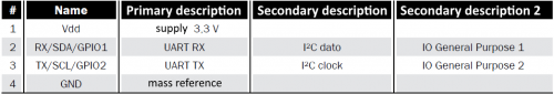
By taking a look inside the board we find the J7 connector: this is a 4-pin connector and respective connections are reported in Table 1. This connector can be used to extend software’s functionality by communicating with I²C, UART or through bit banging with an external device. On this connection a serial 115.200 bps is opened, on which we can print some informative messages.
table1
Finally, J1 connector is reserved to the programming of the main microcontroller and is used only when building the board in order to install the bootloader in a section of the flash memory dedicated to that purpose. The firmware updates can take place through the dedicated webpage, as explained later, or by manually loading the new firmware on the USB stick.
SERVER FTP
In the current firmware version (0.3) an FTP server has been added in order to allow remote upload or download files inside the USB stick. In order to use the FTP server you have two first insert a USB stick with FAT32 formatting inside the USB host of the board and then get a common FTP Client;

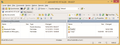
the figure shows the WinSCP application under Windows environment. Naturally, the IP address is the one assigned to the board, number of ports is 21 and access data corresponds to username and password for the admin. The implementation supports FTP clients both with active and passive connections in order to allow an easy configuration, also over the Internet.
Once logged in, you will have the chance to use base functionalities of an FTP server such as upload, download, file or folder renaming and creation or the raising of files and folders. figure shows an example from the resource list displayed after authentication.
FIRMWARE UPDATE
Inside the microcontroller, there is a boot loader that allows updating the firmware without using a programmer. The bootloader is loaded on a dedicated memory section of the microcontroller and will not be modified unless you are going to intervene again with a programmer, that the hand, the app is installed in a memory section which to bootloader can rewrite on, therefore allowing to update the firmware without having to have a dedicated tool. In this section, we are going to show you how to update the firmware to add new features or to correct possible bugs. Under normal usage, all you have to do is access to configuration page is a browser and click on
Advanced, this page shows current firmware and hardware versions. By clicking on Check now you will check if a new version of the firmware is available. This procedure will contact the remote server and, based on the hardware version, will look for possible updates. If there is one, you’ll see a message such as in figure and will see the button labeled Update now.

Before proceeding with the update you will have to insert a USB stick formatted with File System FAT16 or FAT32 and with at least 10 MB available, after that, you can proceed with the update by clicking on Update now. The firmware update procedure can take some minutes and it is important that, during this time, you don’t remove the USB stick nor power off the board, otherwise you might compromise the update.

To make sure the update will not compromise the board’s functioning, once the download of the new firmware is over, the microcontroller will calculate the MD5 of the downloaded file and compare it with that obtained by the remote server, only when there is a correspondence between the two hash strings the software will proceed with the update by copying the content of the file inside the flash memory of the microcontroller. If this is not the case, that is, if some bits have been altered during the download of the file, the PIC will stop upgrading the firmware and will return an error message.

During the download of the new firmware on the USB stick, the microcontroller will continue its operation and the blue LED will continue blinking regularly, when the process is over, the transmitter will then check the MD5 and signal the update started by lighting on the red LED, once the check is over, if everything is okay, the red LED will start blinking slowly, and from this point onward, the update procedure becomes critical and it is important not to power off the board. In this phase, the bootloader will you raise the old app and then install the new application. When the erasing process is over, the red LED on the top will turn off in the central red LED will start blinking fast. Once it stops blinking, and the blue LED goes back to blinking at 1 Hz, the board will be operational again. During all the updating phase, the webpage will autonomously change in order to indicate the advanced stages of the update procedure, for better understanding the update procedure we suggest to wait for the message that will automatically appear once the guided procedure is over.
On the other hand, if you can no longer access to web pages or do not have an Internet connection, you can manually update the firmware.
In this case, you have to manually load the new firmware on the USB stick, rename it exactly in “image.hex” and insert the USB stick in the powered off board, press and hold LEFT and RIGHT keys at the same time for 4 seconds and wait for the update that will take a few seconds and will be indicated by the usual blinking on the red LEDs. Once this stage is over, you will then have to update the webpages: you must access from a browser to the IP address assigned by the DHCP (the URL can be for instance http://192.168.3.4/mpfsupload) or alternatively, in case you are using a browser under Windows environment and NetBIOS support is enabled, you just have to go to http://MCHPBOARD/mpfsupload. From that page, you have to select the page.bin file related to the web pages that you can find on your computer and click on Upload.
From OpenStore
WiFi MP3/Ogg Vorbis Broadcaster

buy linkedin company followers