
We build a Fishino-powered weather station that allows you to collect data from sensors, view them in real-time, send push notifications and save data at regular intervals.
We cannot deny that the occurrence of extreme weather phenomena in areas of the Planet where they have never occurred is due to climate change, partly attributable to man-made pollution.
Preventing the damage caused by such events through weather forecasts is one of the factors that have made weather stations very popular and everything that allows detecting temperature, atmospheric pressure, UV intensity, the concentration of certain gases in the air, etc… To detect and measure these parameters we rely on professional weather stations with high cost, when you need extremely accurate information to build even predictive models, while if the purpose is to be placed in the amateur field, we go on mid-range products. There is, however, a third way, represented by self-construction, as we will demonstrate in this article, in which we propose to build a weather station with a low cost, which will allow you to obtain the main environmental parameters with the addition of some extra features.
The project
The task of the Fishino Weather Station is to collect data from some sensors, in particular:
- DS18B20 for temperature;
- DHT22 for humidity;
- BMP180 for atmospheric pressure;
- ML8511 for ultraviolet rays;
- AS3935 to detect lightning in a 40km radius;
- Anemometer for wind speed;
- RAINMOD rain sensor to detect precipitation.
Then all the values obtained from the surveys will be published on a Web Server in three languages simultaneously. Every 5 minutes all the information will be saved on a microSD card and every 60 minutes will be transmitted as a push notification through the well known Pushetta application.
Hardware
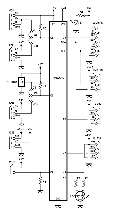
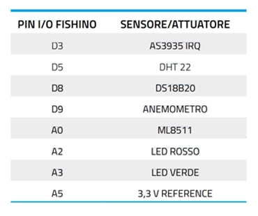
The sensors are placed on a shield (Fig. 1) for Fishino and are interfaced to it as shown in the circuit diagram and Table 1.

Fig.1
Table 1
The sensors DS18B20, DHT22, BMP180 and AS3935 have already been described in previous articles so we are not going to explain their operation; the anemometer (cod. WIND01) and the rain sensor (cod. RAINMOD) are two commercial products by Opne Electronics.
Let’s briefly analyze the circuit, starting from the 5V line to which is connected, in series to a 330 Ω resistor, a green LED (LD1), used to signal that the shield is powered.
The two poles of the anemometer are respectively connected to +5V and D9 pin with a 10K Ω pulldown resistance.
The ML8511 stripline has pins 1 and 4 connected to +3.3V and are used respectively to power the sensor and enable the internal module, while the output (pin number 3) will be connected to analog input A0.
On the PCB there is also a small digital temperature sensor, the DS18B20: the latter has the output pin connected to the JP1 jumper to which the signal coming from pin 2 of the CN1 screw connector is reconnected. The jumper output is connected to pin D8 of the Fishino, with a 4.7k Ω pull-up resistor R1.
We decided to opt for this strategy in order to choose whether to use a wired probe or the on-board sensor, as needed.
The same is true for the DHT sensor and the CN3 terminal board, connected to the JP2 jumper, connected to pin D5 with the pull-up resistor R2.
LD2 is a two-tone (green-red) common cathode LED. The pins are connected, by two 330 Ω resistors R4 and R5, to the A2 and A3 pins of our board respectively.
Firmware
Before analyzing the Fishino sketch we analyze the various libraries that compose it, some of them written by us because they are not available on the Net. Each library can be downloaded for free from www.github.com/signorettae.
Wind.h library
The first sensor for which we have written a handy library is the anemometer: we know that if it makes four complete turns in one second, the wind speed is 10 km/h.
Writing a snippet to report the detected speed and integrating it into the library was quite easy using interrupts. Through these we will prefer a certain operation (in this case the calculation of the instantaneous speed), over others.
To include it in our sketch you just need to write #include <Wind.h>.
Let’s analyze the functioning of our library. When we go to create the object it is necessary to insert a constant that indicates the pin to which the sensor is connected:
Wind wind(wind_pin);
There are a total of 5 functions related to this library, listed below:
bool begin(void);
double getKmhSpeed(void);
double getMtpsSpeed(void);
double getMpHSpeed(void);
double getKtsSpeed(void);
The first is Boolean and is included in the setup. It is used to initialize the sensor and returns the true value in case of a positive result.
The following four functions are used to determine the speed of time in different units of measurement, as our needs change.
The returned variable will be double.
The complete library can be downloaded from the github repository.
The ML8511.h library
Although the ML8511 sensor is equipped with its own operating sketch, created by the Adafruit team, we have opted to integrate it into our own library which allows us to obtain the same results but with greater ease of use.
To include the library this time just type in the preprocessor:
#include <ML8511.h>
When we create the UV object, we must insert two constants:
ML8511 UV(UVOUT, REF_3V3);
The UVOUT pin is the output pin of our sensor, while the REF_3V3 pin indicates that we are using a +3.3V reference; this was necessary because the values involved are very low and very sensitive and therefore to obtain optimal measurements it is advisable to compare the supply voltage with the sensor output voltage.
In this case the functions related to this library are 3 and allow to completely manage the sensor. In particular we will have:
bool begin(void);
double getuvIntensity(void);
double getoutputVoltage(void);
As with the previous library, the begin() function is Boolean, while both getuvIntensity() and getoutputVoltage return a double variable. The first of these returns the UV intensity in mW/m2, while the second returns the output voltage of the sensor, expressed in volts. The complete library can be downloaded from the github repository via the link.
The sketch
The sketch that manages the entire weather station is very articulate but easy to understand.
The “skeleton” of our sketch is the same of the FishinoHomeAuto (available among the Fishino board examples) because it is necessary to use a webserver to upload static files from the board to the client that will try to connect from the browser. The whole sketch is commented in detail, so understanding every single function is not difficult. Below is a summary of the most significant parts of our code, focusing on the most important instructions.
In the first portion of the code (we have the inclusion of libraries like Fishino.h, SPI.h, SD.h and FishinoWebServer.h. We have also added the Fishetta.h libraries for sending push notifications, FishinoRTC.h with its OneWire.h to manage the integrated RTC module and the FishinoDallasTemperature.h for digital temperature sensors. There is also the EVERY.h library that allows you to repeat instructions at regular intervals without having to use the delay function that would block the execution of the entire code. Finally, we find the Wire.h library to manage the I²C bus and the FishinoFlash.h that allows to store the strings in the Flash memory, in order to prevent RAM memory saturation.
We decided to structure our sketch in different functions, in order to discern without difficulty the instructions we want to execute from our microcontroller and eventually to be able to recall them using less code.
In the portion of code displayed in Listing 1, in particular, we can observe all the operations that Fishino will perform to obtain date and time from an NTP (Network Time Protocol) server and to make sure it is correct.
Listing 1
// Get the time in UTC format
uint32_t wifiGetUtc() {
int i;
uint32_t epoch2k;
uint32_t retval = 0;
for (i = 0; i < 10; i++) {
 uint32_t secsSince1900 = Fishino.ntpEpoch();
 while (secsSince1900 <= 1893459661) {
 secsSince1900 = Fishino.ntpEpoch();
 }
 const uint32_t secondsTo2k = 3155673600UL;
 // subtracts from the NTP time the Unix base
 epoch2k = secsSince1900 - secondsTo2k;
 Serial << F(“ \n Seconds elapsed since January 1, 1900 = “) << secsSince1900 << “\n”;
 // print Unix time
 Serial << F(“Time Unix = “) << epoch2k << “\n”;
 // now we convert the NTP time into readable format
 // print hour, minute and second
 // Timer UTC (time at Greenwich Meridian, GMT)
 Serial << F(“Ora UTC: “);
 // print time (counting 86400 seconds per day)
 Serial << ((epoch2k % 86400L) / 3600);
 Serial.print(‘:’);
 if (((epoch2k % 3600) / 60) < 10) {
 Serial << ‘0’;
 }
 // print minutes (counting 3600 seconds per minute)
 Serial << ((epoch2k % 3600) / 60);
 Serial << ‘:’;
 if ((epoch2k % 60) < 10) {
 // in the first 10 seconds of each minute we want the initial zero
 Serial << ‘0’;
}
 // print the seconds
 Serial << epoch2k % 60 << “\n”;
 //It adds 3600 seconds because we are in the GMT +1 zone.
 retval = epoch2k + 3600;
 if (retval > 0)
 break;
 }
return retval;
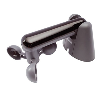
Fig.2
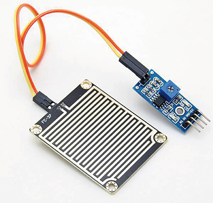
Fig.3
In Listing 2 we have all the code used to load the files, upon specific request, from the microSD card to the client, checking beforehand that the requested files, like the favicon, have not already been saved on the browser cache.
Listing 2
void sendFile(FishinoWebServer& web, const char* filename)
{ Serial << F(“Ram libera: “) << Fishino.freeRam() << “\r\n”;
if (!filename) { web.sendErrorCode(404);
 web << F(“Could not parse URL”);
} else {
FishinoWebServer::MimeType mimeType = web.getMimeTypeFromFilename(filename);
web.sendErrorCode(200);
web.sendContentType(mimeType);
// checks whether certain types of images are cached
if ( mimeType == FishinoWebServer::MIMETYPE_GIF || mimeType == FishinoWebServer::MIMETYPE_JPG || mimeType == FishinoWebServer::MIMETYPE_PNG || mimeType == FishinoWebServer::MIMETYPE_ICO ) web << F(“Cache-Control:public, max-age=900\r\n”);
web.endHeaders();
if (file.open(&root, filename, O_READ)) {
Serial << F(“Lettura del file: “);
Serial.println(filename);
web.sendFile(file); file.close();
} else {
web << F(“Impossibile trovare il file: “) << filename << “\n”; } }
}
Listing 3 contains the complete code that processes the file request, which will then recall the Listing 2 function, as explained above. The code continues with the management of the static files in .htm format.
Listing 3
// handle file requests.
bool fileHandler(FishinoWebServer& web) {
String filename = web.getFileFromPath(web.getPath());
sendFile(web, filename.c_str());
return true;
}
//handle IT language handler.
bool itHandler(FishinoWebServer& web) {
sendFile(web, “INDEX_IT.HTM”);
return true;
}
//handle EN language handler.
bool enHandler(FishinoWebServer& web) {
sendFile(web, “INDEX_EN.HTM”);
return true;
}
//handle DE language handler.
bool deHandler(FishinoWebServer& web) {
sendFile(web, “INDEX_DE.HTM”);
return true;
}
// handle index requests.
bool indexHandler(FishinoWebServer& web) {
#if defined(EN)
sendFile(web, “INDEX_EN.HTM”);
#elif defined(DE)
sendFile(web, “INDEX_DE.HTM”);
#elif defined(IT)
sendFile(web, “INDEX_IT.HTM”);
#else
#error “language is not supported”
#endif
return true;
}
Basically we can access these files (which integrate the request of the other static files) by typing: ipdelfishino/index_xx.htm in the browser address bar, where xx are two characters that correspond to a language. We will use de for German, en for English and it for Italian (Fig. 4 shows the screenshot in Italian). Thanks to these handlers instead, you only need to write: ipdelfishino/xx. The final part is used to determine which file should be opened when typing only the IP address of the board.
Fig.4
Listing 4 groups all the code that sends the data instantly to the client: it creates a client that sends the data in .json format, which will then be processed by the .js file contained in the SD card. We can find in our code a total of 3 status handlers, but we have limited ourselves to the description of the handler in Italian because the code structure is the same for both German and English handlers; only the languages of the data that will be “printed” on the client change.
Listing 4
bool statusHandler(FishinoWebServer& web) {
DateTime dt = RTC.now();
web.sendErrorCode(200);
web.sendContentType(F(“application/json”));
web.endHeaders();
FishinoClient& client = web.getClient(); //Create a client object.
client.println(“{“);
client.print(“ \”umidita\”: \””);
if (hum_sens == false) {
client.println(“sensore scollegato.\”,”);
}
else
if (hum_sens == true) {
client.print(hum);
client.println(“ %\”,”);
}
client.print(“\”temperatura\”: \””);
if (temp == false)
client.println(“sensore scollegato.\”,”);
else
if (temp == true) {
client.print(temperatura);
client.println(“ C\”,”);
}
client.print(“\”pressione\”: \””);
if (pressure_sens == false)
client.println(“sensore scollegato.\”,”);
else {
client.print(P);
client.println(“ mb\”,”);
}
client.print(“\”vento\”: \””);
client.print(speed);
client.println(“ Km/h\”,”);
client.print(“\”uv\”: \””);
client.print(uvIntensity);
client.println(“ mW/cm^2\”,”);
client.print(“\”pioggia\”: \””);
if (rain == true)
client.println(“ Si\”,”);
else
if (rain == false)
client.println(“ No\”,”);
client.print(“\”fulmini\”: \””);
if (AS3935IrqTriggered) {
AS3935IrqTriggered = 0;
int irqSource = AS3935.getInterruptSource();
if (irqSource & 0b0001)
client.print(“Livello del rumore troppo alto, prova a settare la soglia del rumore!”);
else
if (irqSource & 0b0100)
client.print(“Rilevato disturbo”);
else
if (irqSource & 0b1000) {
int strokeDistance = AS3935.getLightningDistanceKm();
if (strokeDistance == 1)
client.print(“Tempesta sopra la testa, attento!”);
else
if (strokeDistance == 63)
client.print(“Rilevato fulmine fuori portata.”);
else
if (strokeDistance < 63 && strokeDistance > 1)
30 31
client.print(“Rilevato fulmine a “);
client.print(strokeDistance, DEC);
client.print(“ km di distanza.”);
}
}
}
else
client.print(“ nessun rilevamento.”);
client.print(“ \”,\n \”dataora\”: \””);
client.print(dt.day(), DEC);
client.print(“/”);
client.print(dt.month(), DEC);
client.print(“/”);
client.print(dt.year(), DEC);
client.print(“ “);
if (dt.hour() < 10) {
client.print(“0”);
client.print(dt.hour(), DEC);
}
else
client.print(dt.hour(), DEC);
client.print(“:”);
if (dt.minute() < 10) {
client.print(“0”);
client.print(dt.minute(), DEC);
}
else
client.print(dt.minute(), DEC);
client.print(“:”);
if (dt.second() < 10) {
client.print(“0”);
client.print(dt.second(), DEC);
}
else
client.print(dt.second(), DEC);
client.println(“\””);
client.print(“}\n”);
client.flush();
client.stop();
return true;
}
else
client.print(dt.hour(), DEC);
client.print(“:”);
if (dt.minute() < 10) {
client.print(“0”);
client.print(dt.minute(), DEC);
}
else
client.print(dt.minute(), DEC);
client.print(“:”);
if (dt.second() < 10) {
client.print(“0”);
client.print(dt.second(), DEC);
}
else
client.print(dt.second(), DEC);
client.println(“\””);
client.print(“}\n”);
client.flush();
client.stop();
return true;
}
The code contained in Listing 5 is used to associate the value obtained from the code in Listing 2 to the variable epochNtp, whose value will be inserted in the integrated RTC module through the RTC.adjust(epochNtp) function;.
Listing 5
void setupRtcfromNTP(void) {
// RTC Init, if required
if (!RTC.isrunning()) {
Serial.print(“RTC non operativo!”);
}
// WiFi Init
if ((epochNtp = wifiGetUtc()) == 0) {
Serial.println(“NTP non disponibile”);
}
else {
RTC.adjust(epochNtp);
// Check New RTC settings
Serial.print(“Epoch dal server NTP :”);
Serial.println(epochNtp);
showDate(“Rtc impostato :”, RTC.now());
}
}
As mentioned before, every time a lightning strike is detected or, at 5 minutes intervals, the data will be saved on the SD card. The instruction block is contained in Listing 6 which will create a DATALOG.txt file and, if already existing, will overwrite it.
Listing 6
bool saveData(String data) {
if (!file.isOpen()) // check if file is open.
datalog.open(&root, “datalog.txt”, O_CREAT | O_WRITE | O_APPEND); // If file is not open, it will be opened.
if (datalog.isOpen()) {
// if datalog is open, it will save data with an end line.
if (datalog.write(data.c_str())) {
datalog.write(“ \n”);
Serial.println(“Dati salvati”);
}
else
Serial.println(“Errore nella scrittura sul file “);
datalog.sync();
datalog.close();
return true;
}
else {
Serial.println(“Errore nell’apertura del file datalog.txt”);
return false;
}
}
The code in Listing 7 is intended to collect data from the various sensors and associate them with the relevant variables, which will be processed later. Listing 8 is the code of the setup, which in particular will initialize the I/O pins, the I²C and SPI buses and the various sensors. Subsequently, it will pass to the connection of the access point, the setting of the RTC module and the SD card.
Listing 7
void getSensorsData(void) {
uvIntensity = uv.getuvIntensity();
speed = wind.getKmhSpeed();
sensors.requestTemperatures();
temperatura = sensors.getTempCByIndex(0);
hum = dht.readHumidity();
char status;
//double T, p0, a;
status = pressure.startTemperature();
if (status != 0)
{
// Wait for the measurement to complete:
delay(status);
// Retrieve the completed temperature measurement:
// Note that the measurement is stored in the variable T.
// Function returns 1 if successful, 0 if failure.
status = pressure.getTemperature(T);
if (status != 0)
{
// Start a pressure measurement:
// The parameter is the oversampling setting, from 0 to 3 (highest res, longest wait).
// If request is successful, the number of ms to wait is returned.
// If request is unsuccessful, 0 is returned.
status = pressure.startPressure(3);
if (status != 0)
{
// Wait for the measurement to complete:
delay(status);
// Retrieve the completed pressure measurement:
// Note that the measurement is stored in the variable P.
// Note also that the function requires the previous temperature measurement (T).
// (If temperature is stable, you can do one temperature measurement for a number of pressure measurements.)
// Function returns 1 if successful, 0 if failure.
status = pressure.getPressure(P,T);
}
}
}
if (temperatura == -127.00)
temp = false;
else
temp = true;
if (P == 0.00)
pressure_sens = false;
else
pressure_sens = true;
if (digitalRead(rainpin) == HIGH)
rain = false;
else
if (digitalRead(rainpin) == LOW)
rain = true;
if (isnan(hum))
hum_sens = false;
else
hum_sens = true;
}
Listing 8
void setup(void) {
Serial.begin(115200);
//Initialize I/O pins and sensors
pinMode(rainpin, INPUT);
pinMode(statusled_green, OUTPUT);
pinMode(statusled_red, OUTPUT);
digitalWrite(statusled_red, HIGH);
digitalWrite(statusled_green, LOW);
wind.begin();
uv.begin();
dht.begin();
sensors.begin();
sensors.setWaitForConversion(false);
sensors.setResolution(12);
sensors.requestTemperatures();
SPI.begin();
if (pressure.begin())
Serial.println(“BMP180 inizializzato correttamente”);
else
Serial.println(“Inizializzazione del BMP180 fallita”);
Serial.println(“Avvio...”);
Wire.begin();
Wire.setClock(400000);
AS3935.reset();
if (!AS3935.calibrate())
Serial.println(“Tuning out of range, check your wiring, your sensor and make sure physics laws have not changed!”);
AS3935.setIndoors();
AS3935.setNoiseFloor(1);
AS3935.setSpikeRejection(2);
AS3935.setWatchdogThreshold(1);
AS3935.enableDisturbers();
printAS3935Registers();
AS3935IrqTriggered = 0;
attachInterrupt(digitalPinToInterrupt(IRQ_PIN), AS3935_ISR, FALLING);
connectToAp();
setupRtcfromNTP();
pinMode(SD_CS, OUTPUT);
digitalWrite(SD_CS, HIGH);
Serial << F(“Inizializzando la micro SD...\n”);
if (!card.init(SD_CS))
Serial << F(“Apertura dell’sd fallita!\n”);
else
if (!volume.init(&card))
Serial << F(“Inizializzazione del volume fallita!\n”);
else
if (!root.openRoot(&volume))
Serial << F(“Apertura della root fallita!\n”);
else
hasFilesystem = true;
if (!hasFilesystem) {
Serial << F(“Filesystem non presente. -- Stop.\n”);
while (1)
;
}
;
web.addHeader(F(“Content-Length”));
web
.addHandler(F(“/”) , FishinoWebServer::GET , &indexHandler)
.addHandler(F(“/it”) , FishinoWebServer::GET , &itHandler)
.addHandler(F(“/en”) , FishinoWebServer::GET , &enHandler)
.addHandler(F(“/de”) , FishinoWebServer::GET , &deHandler)
.addHandler(F(“/data.js”) , FishinoWebServer::GET , &statusHandler)
.addHandler(F(“/data_en.js”) , FishinoWebServer::GET , &statusHandler_en)
.addHandler(F(“/data_de.js”) , FishinoWebServer::GET , &statusHandler_de)
.addHandler(F(“/” “*”) , FishinoWebServer::GET , &fileHandler)
;
Serial << F(“Inizializzazione avvenuta!\n”);
Serial << F(“Avviando il web server...\n”);
web.begin();
Serial << F(“Pronto ad accettare le richieste HTTP.\n”);
digitalWrite(statusled_green, HIGH);
digitalWrite(statusled_red, LOW);

Fig.5
If any problem should arise during the initialization of the SD card, the execution of the code will be stopped permanently, making it necessary to reset the card manually.
From the start of the setup, the red signal LED will remain lit until the last operation of the setup, i.e. the start of the webserver, is performed. After this operation, the red signal LED will be turned off and the green signal LED will light up.
Now pay attention to this snippet:
web
.addHandler(F(“/”) , FishinoWebServer::GET , &indexHandler)
.addHandler(F(“/it”) , FishinoWebServer::GET , &itHandler)
.addHandler(F(“/en”) , FishinoWebServer::GET , &enHandler)
.addHandler(F(“/de”) , FishinoWebServer::GET , &deHandler)
.addHandler(F(“/data.js”) , FishinoWebServer::GET , &statusHandler)
.addHandler(F(“/data_en.js”) , FishinoWebServer::GET , &statusHandler_en)
.addHandler(F(“/data_de.js”) , FishinoWebServer::GET , &statusHandler_de)
.addHandler(F(“/” “*”) , FishinoWebServer::GET , &fileHandler)
;
The latter is used to initialize the handlers of the webserver we dealt with previously. If they were not initialized, the Web Server would not know how to behave in case of a request. The loop calls the getSensorData() function, specified in Listing 8, to collect data from the sensors, process all the data of the webserver and query the WiFi module about the connection status with the Fishino.status() function. If the module is correctly connected to the access point, the green LED will remain on and the red LED will remain off. Otherwise the green LED will be off and the red LED will be on. Afterw.
ards the message string will be created that will contain the text that will be saved on the SD card and sent through push notification. Depending on the language chosen in the preprocessor, both the notifications and the datalog can be in Italian, English or German.
For what concerns the data processing of the AS3935 sensor we refer to the article published in the issue 217 of June/July 2017.
The complete sketch with all libraries is available here.
Conclusions
This is the end of the presentation of the Fishino Weather Station: with this project we have provided you with the basics to create a weather station that can be customized and adapted to individual needs to have at your fingertips, on browsers, but also on smartphones, notifications (Fig. 6) and weather parameters constantly updated.
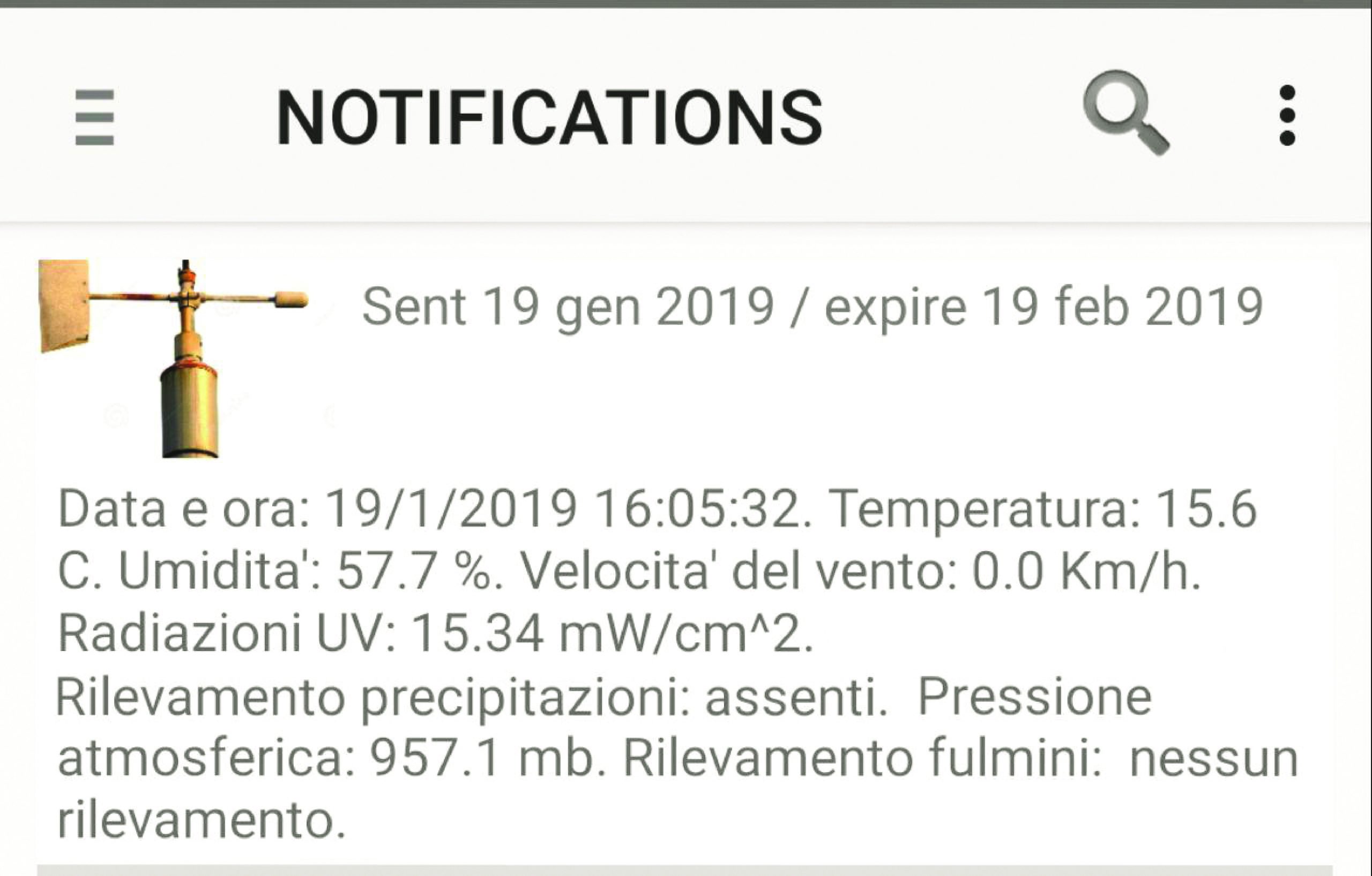
Fig.6
Components list
R1, R2: 4.7 kohm
R3, R4, R5: 330 ohms
R6: 10 kohm
DHT Sensor: DHT22
AS3935: Fulimini Sensor with AS3935
BMP180: BMP180 pressure sensor
ML8511: ML8511 Light Sensor
RAIN: Rain sensor
WIND: Wind sensor
DS18B20: DS18B20 Sensor
RTD: Microswitch
LD1: LED 5 mm green
LD2: LED 5 mm bicolor C.C.
Various:
- 3-way male strip (2 pcs.)
-
Male Strip 4 ways (2 pcs.)
-
Male Strip 5 ways
-
7 Way Male Strip
-
4-way female strip
-
5-Way Female Strip
-
7 way female strip
-
2-way 2.54mm pitch clamp
-
3-way clamp 2.54mm pitch (3 pcs.)
-
Strip 6 ways for Arduino
-
Strip 8 ways to Arduino (2 pcs.)
-
Strip 10 ways to Arduino
-
Jumper (2 pcs.)
-
S1358 printed circuit board (55×69 mm)
From openstore
Breakout with UVB sensor ML8511
Wind sensor with adjustable arm
Humidity and temperature sensor
