
Disinfects masks and objects by exposing them to ultraviolet rays generated by innovative UVC LEDs, protecting them from viruses and bacteria.
In all situations where it is necessary to sanitize, sterilize and otherwise disinfect objects potentially depository of infectious particles (viruses, bacteria, etc..) we make use of medical and surgical tools and equipment that are suitable from time to time; it is not only the case of measures to prevent the spread of COVID-19, now part of our lives since the beginning of the year, but also the routine involving doctors’ offices, hospital wards and domestic environment where you have to care for people.
One of the techniques of sanitization or, better, sterilization, widely used for years, is based on exposure to type C ultraviolet light, which has a considerable energy and that, from studies conducted, has wavelengths that are lethal to viruses and bacteria. That’s why we thought of exploiting it in a project that will certainly be useful to you, because it is a sanitizer of objects such as the famous surgical masks used to protect against COVID-19 infection.
Of course, in order to keep up with the times, we thought of making something that would be marked by the presence of an innovative technological solution. Specifically, it is the adoption of solid-state lighting fixtures, i.e. brand new UV-C LEDs instead of conventional LED or low-pressure mercury vapor lamps.

THE ACTION OF ULTRAVIOLET
UV-C has long been known to disinfect pathogens (a joint study by the University of Milan, the Institute of Astrophysics and the Institute of Tumors on the correlation between UV exposure and the spread of COVID-19 infection was recently published) and has been widely used for over 40 years to disinfect drinking water, wastewater, air, pharmaceuticals, surgical instruments (and dental instruments) and surfaces from a wide range of human pathogens.
All bacteria and viruses tested (many hundreds over the years, including recent viruses) respond to disinfection by UV-C (in truth, also UV-B) meaning that they are killed by exposure to such radiation. Some organisms have been shown to be more sensitive to UV-C disinfection than others, but all tests to date respond to appropriate doses.
According to the International Ultraviolet Association (https://iuva.org), the ultraviolet spectrum corresponding to sterilization capability is about 200-300nm and therefore very narrow; to be exact, the bactericidal range extends between 280nm and 300nm. Theoretically the wavelength of 265 nm is considered the optimal one because it corresponds to the peak of the absorption curve of DNA / RNA: most of the peaks for viruses and bacteria is at 265 nm.
This explains why a single wavelength can be used to eliminate all bacteria, although each family has different optimal absorption wavelengths.
Generally, the power intensity, wavelength, and duration of irradiation are used to determine the bactericidal effect.
For example, there may be multiple bacteria in water with different optimal absorption wavelengths.
For any given wavelength of germicidal UV, it is necessary to calculate the power and irradiation time to achieve the desired level of disinfection.
THE PROJECT
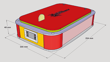
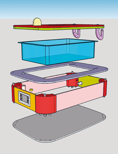
Let’s get to the heart of the description of our apparatus, which consists of a plexiglass container with a hinged lid inside which, facing down, is a UV-C LED strip marketed by Open Electronics (also online at www.open-electronics.org with the product code UVC4LEDSTRIP) that houses, on a PCB, four SMD LEDs emitting ultraviolet UV-C, the ideal range as a method of sterilization and sanitization of surfaces and objects. The wavelength of the radiation emitted by the LEDs is between 265 and 278nm.
The LEDs used are type 3535, 5mW power each and with an emission angle of 120°, then sufficiently wide to “illuminate” a large surface with UV-C even a few inches away. Our strip is shown in Fig. 1.
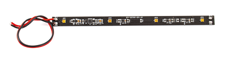
Fig. 1
These strips are supplied with a continuous voltage of 5÷12 Vdc and integrate the current regulator for LEDs, which allows us to turn them on simply by powering them, safe in the knowledge that the on-board controller will adjust the operating parameters in the best way.
The dimensions are 200x12x3.6 mm and therefore with a strip we can cover the lid of the container and illuminate an area that, with sufficient approximation, considering the angle of irradiation of each diode, is uniform about 10×26 cm at a height of 4 cm.
The LED strip is powered through the closure of the cover, in correspondence of the measure of which is placed a reed switch used to power a programmable timer display, also available from Open Electronics (product code DPTIMER12V) and used to physically drive the strip according to the setting that we are going to make manually.
In this regard, it should be noted that this timer (Fig. 2) provides many possibilities for operation; it is in fact a multifunction panel timer with red LED display for one time (TIMER1) and green LED display for another time (TIMER2), buttons for settings, output relay capable of switching loads of various kinds.
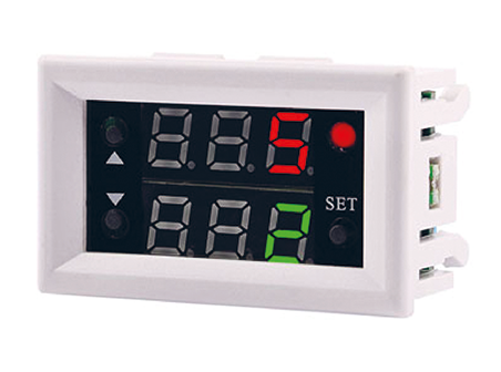
Fig. 2
The time for each of the two timers (timing) can be set from 0 to 999 seconds, 0 to 999 minutes, 0 to 999 hours. In addition, you can choose one of the following modes of operation:
1. when the relay is switched on, it is deactivated; when the time set for TIMER1 expires, the relay is activated;
2. when the relay is switched on, it is active, at the end of the time set for TIMER1 the relay is deactivated;
3. when switched on, the relay is inactive, at the end of the time set for TIMER1 the relay is activated and at the end of the time set for TIMER2 it returns to rest;
4. when switched on, the relay is active, at the end of the time set for TIMER1 the relay switches off, at the end of the time set for TIMER2 it switches on;
5. cyclic operation 1: when the relay is switched on, it is deactivated, when the time set for TIMER1 has elapsed the relay switches on and when the time set for TIMER2 has elapsed it switches off again;
6. cyclic operation 2: when switched on, the relay is active, at the end of the time set for TIMER1 it switches off, then once the time set for TIMER2 has elapsed it switches on again.
In our project we have chosen mode 3 with a start-up preparation time (useful, for example, to remind us that the ultraviolet emission is about to start) of 10 seconds, during which the relay is at rest, and a UV exposure duration of 5 minutes (300 seconds); these times, as specified above, can be modified at will by means of the buttons provided, located on the front panel of the device and better described in Fig. 3.
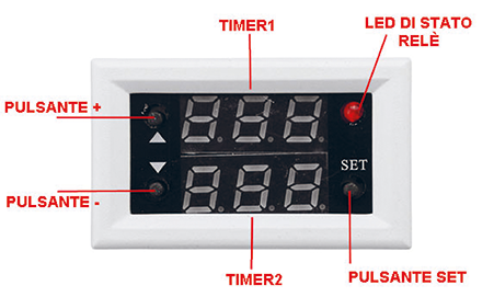
Fig. 3
The procedure for setting the operating mode and times of TIMER 1 and TIMER 2 will be described below. The timer is powered at 12 Vdc and for user control integrates a relay with exposed contacts C (common) and NO (normally open) of the exchange, capable of switching currents in the order of 10A in circuits operating at 250 Vac and 20 A at 14 Vdc.
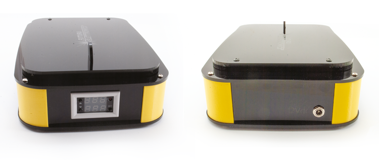
The relay exchange is made accessible by a terminal block located on the back of the timer, together with the power supply one, as you can see in the picture in Fig. 4.
In our application, the relay has to switch relatively little and therefore we have no problem to do everything with the timer, without resorting to external switching devices: in fact, the strip absorbs about 500 mA, which for the relay is a very low load.
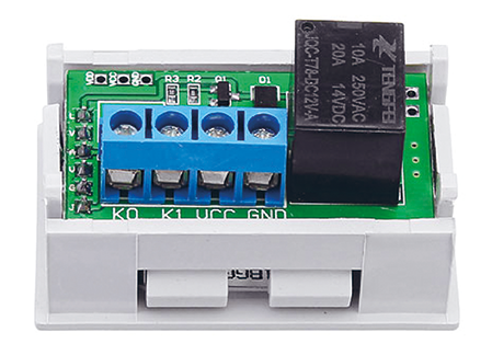
Fig. 4
THE PROJECT
Once you have completed the assembly, you must set the timer before using it. To set the timer, power up the circuit (maybe to avoid unwanted switching on of the LED strip, disconnect the positive from the timer relay switch) and make sure that the timer is constantly powered up; for this purpose, it is convenient to momentarily bridge the reed switch. Then briefly press the SET button and when the first display (TIMER1) flashes, press the BUTTON+ or BUTTON- to set the time of TIMER1 (i.e. the time that elapses before the UV-C LED light is energised) and then press SET again and then BUTTON+ and BUTTON- to set the time of TIMER2 (LED on time) on the display.
This value is generic, so you have to press and hold the SET button (about 5 seconds) to enter the settings, i.e. to tell the timer what it will mean: hours, minutes or seconds. So after a long press on SET you will see on the first display “P0” and on the second “0”; in this mode the time you will set for TIMER1 and TIMER2 will be in seconds; if you want it to be in minutes or hours press the buttons with arrows until you see the corresponding setting, considering that P0 and 0 means seconds, P0 and 1 minutes and P0 and 2 hours. We are interested in time in seconds, so leave the arrow buttons alone and briefly press the SET button again to go to the “Operating Mode” setting; here you must use the arrow buttons to select one of the six modes described on the previous pages: the upper display shows P1 and the lower display 1.

Since we are interested in running the timer in mode 3, use the arrow buttons until 3 appears on the lower display.
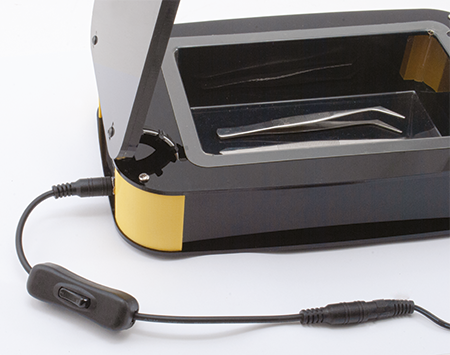
At this point, do not press any buttons for at least 5 seconds, so that the timer exits the setting mode and switches to normal operation: the timer is ready to operate with the times you have set. Remove the short-circuit bridge of the reed switch and your sanitizer is ready; put in the masks you use to protect yourself from COVID-19 or the objects you want to disinfect and close the lid: the timer will start and after 10 seconds the LEDs will light up. A note before we finish: if you have old circuits that use EEPROMs, you can use the sanitizer to erase them.
From Openstore
Multifunction panel mini timer – 12 VDC

I read that UV can degrade the fibres in surgical masks and its not recommended by the manufacturers! I just isolate mine for 5 days,