
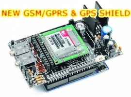
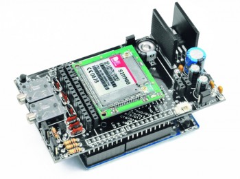
A few months ago, we presented a powerful shield that can enable devices from the Arduino family (Uno and Mega) to interface with the SIMCOM modules SIM900 and SIM908.
Such modules provide integration with the world of GSM, GPRS and GPS and all is achieved through very simple Arduino commands thanks to the open-source dedicated library. It is possible to place phone calls or to send SMS with few simple functions.
From the time of the last post presented, the library has been also improved with additional features such as DTMF tones management capabilities and the ability to send e-mails.
In this article, we’ll discuss the main innovations introduced in the software library and then, in future posts, we’ll show more examples of its features.

SOFTWARE NEWS
This open source library to interface with the SIM90x module, is in continuous development and can be found online at http://code.google.com/p/gsm-shield-arduino/.
Let’s remember that, for reasons related to the optimization of RAM usage, the library is divided into classes, each with a specific function. As a result, if you want to use the phone calls, you should be including the related class:
#include “call.h”
In case of sms you’ll have include in the sketch:
#include “sms.h”
Th functionality to send DTMF (Dual-Tone Multi-Frequency) tones, is included in the class for call as it’s related.
To use these functions you just need to include the corresponding file and instantiate the object within the program. The functions shown in Table 1 refers to an object created with the following command at the beginning of the sketch: CallGSM call;
|
void SendDTMF(char* number_string, int time) |
During an active call, it sends the string passed as a parameter, specifying the duration of each tone in tenths of a second. The string can be composed of the following characters: 0-9, #, *, AD. |
call.SendDTMF(“1,2,3,4,*”,2) |
Table 1

EXAMPLE 1
This first example shows how to make a call to a preset number when an alarm condition occurs.
Such a condition occurs when the chosen analog input pin goes to less than 50. Remember that Arduino samples input voltages with 10 bits values: with the basic configuration, 1023 is equivalent to 5 volts, 50 will amount to approximately 0.25 volts.
A similar condition, with the appropriate choice of threshold values, may represent exceeding a limit temperature by a heat sensor or, similarly, the increase (or decrease) of brightness measured by a photoresistor.
With a few simple steps is possible to realize an alarm that able to alert about an alarm condition without additional expenses (it would be even sufficient to refuse the call, so to avoid connection charges).
Let’s see how to achieve that: if the alarm condition occurs a call is made through the above-mentioned function call.Call (number).
To prevent a phone call is made when there is already one active, the function first checks the state of the phone calls.
To check the status of the call, simply call the function call.CallStatus() and make sure that it returns a value other than CALL_ACTIVE_VOICE.
#include "SIM900.h"

#include <SoftwareSerial.h>

#include "call.h"

CallGSM call;

char number[]="3921234567";

int value=0;

int pin=A0;

void setup()

{

 Serial.begin(9600);

 if (gsm.begin(2400))

   Serial.println("\nstatus=READY");

 else Serial.println("\nstatus=IDLE");

};

void loop()

{

 value=analogRead(pin);

 Serial.println(value);

 if(value<50){

   Serial.println("Allarme");

   if(call.CallStatus()!= CALL_ACTIVE_VOICE){

     Serial.println("Chiamo");

     call.Call(number);

   }

   else

     Serial.println("Chiamata in corso");

 }

 delay(1000);

};

<a href="https://www.open-electronics.org/wp-content/uploads/2013/05/gsm-shield-SIM908_s.jpg"><img class="aligncenter size-full wp-image-4392" alt="gsm-shield-SIM908_s" src="https://www.open-electronics.org/wp-content/uploads/2013/05/gsm-shield-SIM908_s.jpg" width="350" height="152" /></a>
EXAMPLE 2
The above example could create some problems in case of values that close to the threshold level: in fact, because of the noise on the sensor or even for rapid oscillations around the threshold, the alarm may repeatedly be activated or inactivated, generating problems.
To avoid this you should use a hysteresis cycle or just a filter on the measurement.
Regarding hysteresis, two different threshold values are chosen to delay the activation and deactivation of the alarm, so that for the alarm to turn off it is necessary to move away significantly from the alarm condition.
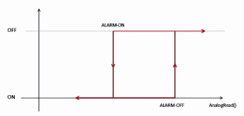
Now we’ll show, instead, how to realize a small discrete-time low-pass filter of the first order to avoid that the high frequency oscillations may accidentally repeatedly activate the warning condition.
Unlike the previous example, we’ll use the following additional variables:
int mov_av=0;
float threshold=0.9;
In the setup we’ll initialize the first sample with the command:
lpf_val =analogRead(pin);
And in the loop() we will update the as it follows:
value=analogRead(pin);
lpf_val = lpf_val *threshold+(1-threshold)*value;
The variable lpf_val therefore will contain the filtered value. The cutoff frequency is determined by the value of the threshold (in this case it’s 0.9). Values that are close to one lower the cutoff frequency, vice versa, values that are close to zero raise the cutoff frequency by passing also the higher frequencies.
Obviously the condition will be evaluated on the filtered value with:
if (lpf_val <50)

EXAMPLE 3
In this example, that is similar to the above, we will make a call each time the state of a digital input changes state. In case of answer, you’ll hear a single DTMF in case the status on the chosen input is low, conversely two DTMF mean its high.
In future versions of SIM908 a DTMF tones decoder will also be implemented which you can use to decipher the tones sent by the user to the SIMCOM module. This feature is already available on the SIM900 sold in our store (not all SIM900 available in the market have this feature).
Looking at the code, there is a simple logic for alarm condition, that activates the communication routine for the given number.
As in previous examples, the presence of an active call is checked: if no calls ongoing, a new one is placed to the preset number, while if a call is ongoing the status of the selected input is first checked and subsequently this is communicated via DTMF tones.
call.SendDTMF(“0”, 1);
call.SendDTMF(“0,0”, 1)
The first command sends a string made of one number, on the contrary, the second one sends a string composed of two characters (note the use of the comma to separate characters) .
Adding a delay is key to avoid communicating continuously via the DTMF tones with the risk of misinterpreting the communication. In this case we have chosen a delay of 5 s.
At the end of the code you can see how the status update is made only when a call is not active, to avoid making different communications during the same call.
#include "SIM900.h"

#include <SoftwareSerial.h>

#include "call.h"

CallGSM call;

char number[]="3921234567";

int value=0;

int value_old;

int pin=9;

void setup()

{

 Serial.begin(9600);

 if (gsm.begin(2400))

   Serial.println("\nstatus=READY");

 else Serial.println("\nstatus=IDLE");

 value=digitalRead(pin);

 value_old=digitalRead(pin);

};

void loop()

{

 value=digitalRead(pin);

 if(value!=value_old){

   Serial.println("Allarme");

   if(call.CallStatus()!= CALL_ACTIVE_VOICE){

     Serial.println("Call");

     call.Call(number);

     delay(1000);

   }

   else{

     Serial.println("Call active");

     if(value==0){

       call.SendDTMF("0", 1);

       delay(5000);

     }

     else{

       call.SendDTMF("0,0", 1);

       delay(5000);

     }

   };

 }

 if(call.CallStatus()!= CALL_ACTIVE_VOICE){

   Serial.println("Update");

   value_old=value;

 }

 delay(500);

};
EXAMPLE 4
In contrast the previous example, in this case we will decide when to query Arduino for the verification of the inputs: this is done thanks to a call.
The module will check if the calling number is among those authorized and eventually accept the call, communicating then with DTMF tones.
Regarding the authentication mechanism, we will use the function:
call.CallStatusWithAuth(number,8,10);
which will check if the number that is making the call is saved on the SIM in a position between the 8 and 10. The first string passed as a parameter will contain the the caller number. It is always advisable to choose not too large intervals, since each SIM query to get the numbers from the address book, requires few tenth of a second.
|
byte CallStatus(void); |
Returns the state about the phone calls. |
The possible output byte are listed under the following names:
CALL_NONE or 0: No call.
CALL_INCOM_VOICE or 1: An incoming call.
CALL_ACTIVE_VOICE or 2: Active Call
.
If(call.CallStatus()== CALL_ACTIVE_VOICE)
Serial.println(“CHIAMATA IN CORSO”);
byte CallStatusWithAuth(char* phone_number, byte first_authorized_pos, byte last_authorized_pos);
Unlike the previous distinguish whether the active call, or on arrival, belongs to a number saved on the SIM in a position between the initial and final, passed as parameters. The possible output byte are listed under the following names:
CALL_NONE or 0: No call.
CALL_INCOM_VOICE_AUTH or 3: Incoming call from a number authenticated.
CALL_INCOM_VOICE_NOT_AUTH or 4: Incoming call from a number not authenticated.
If(call.CallStatusWithAuth (number,9,9)==CALL_INCOM_VOICE_AUTH)
Serial.println(“INCOMING CALL FROM AN AUTH NUMBER, SAVED ON THE SIM IN POSITION 9”);
We’ll show you only the portion of code that regards the number verification, where to find also the functions to manage the call answer and closure:
call.PickUp();
call.HangUp();
|
state=call.CallStatusWithAuth(number,8,10); if(state==CALL_INCOM_VOICE_AUTH) { […] } delay(500); }; |

EXAMPLE 5
Always in a purpose of saving expenses, let’s see how to make a similar example without generating any costs related to making calls.
The idea is to communicate the status of the input by refusing (or not) an incoming call. If the state is low, there will be no action, leaving the module ring. Conversely, if the input state is high, the call will be rejected.
In this way you can be aware of the state without worrying about the cost of communication.
Inside the code you will notice the authentication mechanism. Indeed, in the case of an incoming call by an unauthorized number, no action is taken, leaving the module ringing regardless of the state of the inputs.
#include "SIM900.h"

#include <SoftwareSerial.h>

#include "call.h"

CallGSM call;

char number[15];

int value=0;

int pin=9;

byte state;

void setup()

{

 Serial.begin(9600);

 if (gsm.begin(2400))

   Serial.println("\nstatus=READY");

 else Serial.println("\nstatus=IDLE");

 pinMode(9,INPUT);

};

void loop()

{

 state=call.CallStatusWithAuth(number,8,10);

 //Serial.println(state);

 if(state==CALL_INCOM_VOICE_AUTH)

 {

   value=digitalRead(pin);

   delay(1000);

   Serial.println("Chiamata in corso da numero autorizzato");

   if(value==0){

     delay(1000);

   }

   else{

     Serial.println("Hang Up");

     call.HangUp();

     delay(1000);

   }

 }

 delay(500);

};
|
With this post we shown you just some of the features that our GSM shield provides through the simple use of phone calls.

[…] A few months ago, we presented a powerful shield that can enable devices from the Arduino family (Uno and Mega) to interface with the SIMCOM modules SIM900 and SIM908. […]
[…] Using the GSM/GPRS & GPS Shield: call examplesPosted 7 days ago […]
Guys, do not forget to look at the GSM-GPS Shield from HW Kitchen. We have just got it and it looks impressive!
can we use this device with other electronic component. for an example, if somebody push the button, it will automatically trigger this device and send the sms to the user. can we do it like that??
Yes of course. see other post
[…] Using the GSM/GPRS & GPS Shield: call examplesPosted 19 days ago […]
do I have to put my own female stacking pins, if I want to put another shield on top of the GSM/GPRS/GPS shield?
This is only the prototype, we sell the shield with the Arduino Strip
https://store.open-electronics.org/index.php?_route_=Arduino/Products/8pin_Arduino_Stackable_Headers
Hi, I´m trying to use the example 5, the problem is that i don´t know how to set authorized phones number so I can answer the call, pls help me. Thank You.
state=call.CallStatusWithAuth(number,8,10);
I firts tested example 3, it works just fine but so far don´t figure out how to answer the call, by pressing a button or automatically
Glen, any luck here? I am trying to figure out how to store a few numbers to the SIM myself. Thanks.
i am using both GSM shield & Relay Shield in ” Power Management System ” can you Help me This??
Please
Hi,
I uploaded GSM_GPRSLibrary_Call.ino on my Arduino Uno.
I have an issue, after module is ready (status=READY), I receive in continuous mode (in serial monitor), the following lines:
And I’m not able to send any other command, but I can see that somebody call on that SIM number. Any Idea?
The GPS library’s working well!
ATT: OK
RIC: NO STRING RCVDATT: OK
RIC: NO STRING RCVDATT: OK
RIC: NO STRING RCVDATT: OK
RIC: NO STRING RCVDATT: OK
RIC: NO STRING RCVDATT: OK
RIC: NO STRING RCVDATT: OK
RIC: NO STRING RCVDATT: OK
RIC: NO STRING RCVDATT: OK
RIC: NO STRING RCVDATT: OK
RIC: NO STRING RCVDATT: OK
RIC: NO STRING RCVDATT: OK
RIC: NO STRING RCVDATT: OK
RIC: NO STRING RCVDATT: OK
RIC: NO STRING RCVDATT: OK
RIC: NO STRING RCVDATT: OK
RIC: NO STRING RCVDATT: OK
RIC: NO STRING RCVDATT: OK
RIC:
OK
ATT: +CLCC: 1,1,4,0,0
RIC:
OK
ATT: +CLCC: 1,1,4,1,0
RIC:
OK
ATT: +CLCC: 1,0,0,0,0
RIC:
OK
ATT: +CLCC: 1,1,0,0,0
RIC:
OK
ATT: +CLCC: 1,1,0,1,0
RIC:
OK
ATT: +CLCC:
RIC:
OK
ATT: OK
RIC:
OK
Try to reduce the baud to 2400
Incredible examples, I don´t understand what is the reason to use the Software Serial library if you are not declaring the pins to use. Could you tell me what are the pins that the program uses to active the gsm please, because I have a trouble when I try to connect a matricial keypad and I think the problem is where I connect the pins for the matricial keypad THANKS!!
See the library. Here you can find the used pins to comunicate with the module
Why do the Rx/Tx from SIM900 need to be connected to the 18/19 of MEGA? Cant they also be connected to the other Rx/Tx pins on the board? And how in code do I edit that if in fact I wish to use other pin sets on my MEGA?
Yes you can, but Mega has more HW serial
ATA is the command for answering a call. AT+CPBR=? reads all phonebook entries while CPBS= reads a specific entry and CPBW= [,, [,[]]] writes a number to memory.
I am having trouble getting the sim card to register to the network, I see 1.5 volts on SimVDD then nothing. All searches on internet seem to point to power supply issues, but this should be a working design by OE, The GPS is working fine, I can communicate with the Sim908 using AT command example, but anything to do with sim just replies No Sim inserted! Why is this, this is just so frustrating!!!!!
You have to remove the welding from the rear of the PCB
i am trying to receive the dtmf tones but it is not happening , any one can help me?
Are you using our SIM900? Only our SIM900 decode DTMF tone
How can I check the status of the call by using AT Command?
Use the commanda AT+MORING=1
hi, I am doing example 5 . With arduino uno and gsm 900A, Rx of gsm shield
to pin 3 of arduino and Tx to pin 2. Power supply to shield is external with 2A adapter and not from arduino board. I changed Rx-Tx pin but serial monitor response is same as follow.
————–>>>>>
DB:NO RESP
DB:NO RESP
DB:NO RESP
Trying to force the baud-rate to 9600
1200
ATT: OK
RIC:
OK
2400
ATT: OK
RIC:
OK
4800
ATT: OK
RIC:
OK
9600
ATT: OK
RIC:
OK
19200
ATT: OK
RIC:
OK
38400
ATT: OK
RIC:
OK
57600
ATT: OK
RIC:
OK
115200
ATT: OK
RIC:
OK
ERROR: SIM900 doesn’t answer. Check power and serial pins in GSM.cpp
status=IDLE
<<<<<<———————–
Checked GSM.cpp and it is
#define _GSM_TXPIN_ 2
#define _GSM_RXPIN_ 3
Any idea what is the problem.
How is the the led blinking: every second or every 3 seconds?
Its blinking aftet every 3 seconds. So it is connected to network.
I can never remember this but have you tried the pins the other way around? Which library are you using? Have you tried connecting directly to the sim?