Using Fishino and Octopus driver, we play a small toy keyboard that will reproduce musical melodies originally born as Nokia ringtones.
For many years, electronic keyboards, especially music synthesizers, have had the possibility to play tunes independently, if adequately piloted through the MIDI interface or by reproducing standard format files uploaded from external mass storage devices. However, what we aim to do here is to use much more affordable musical instruments to play tones of our choice, such as small keyboards and toy keywords that can be purchased in department stores for a few tens of euros, which for obvious reasons do not have data interfaces or slots for external mass storage devices and therefore cannot be electronically piloted. In this cases, the only solution is to play them the traditional way, by acting on the keyboards with something capable to transform musical notes in mechanical commands. In short, an electronic – mechanic interface.
We managed to do this: the project we introduce in these pages, is a gadget we developed in order to be used in various occasions, such as a demo in a display or in the toys section of a shop, or as a source of entertainment for kids and adults alike, for instance, at a robotics fair shows.
We thought about an automated solution composed of a small robot that will play the toy keyboard for us. The melodies we have chosen are not any audio files but, for practical purposes, we chose the ringtones developed by Nokia and defined as RTTTL (Ring Tone Text Transfer Language) “played” by the manufacturer’s cell phones.
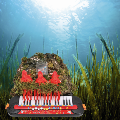
Our robotic platform, which is to be applied at the keyboard and adapted to its shape and keys, is composed of a “brain” based on the now popular Fishino Uno board, and an actuation system made with Octopus driver, which we have already introduced in this post.
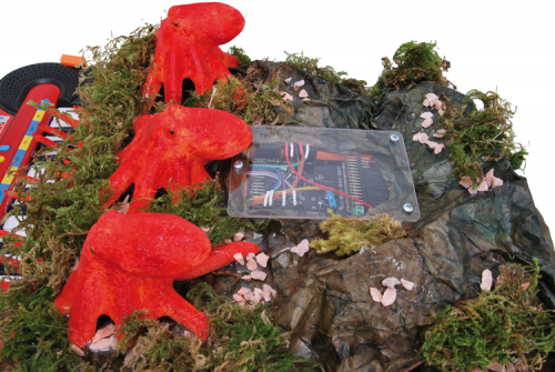
Tones are handled by a sketch specifically created for our Fishino Uno board, while physical control of makes use of an electromechanical system composed of 24 servomotors managed by two Octopus shields to which the eight tentacles of three jolly 3D-printed PLA red octopuses are connected, actioned by the servos through a simple but precise leverage mechanism.

Using the 24 servos we can manage two octaves (on the keyboard we use they correspond to 4th and 5th of the piano), therefore 12 keys for octave corresponding to the 7 notes (Do, Re etc.) plus the semitones (sharp and flat).
For those of you who want more information in this regard, keys of each octave are conventional as below:
C = DO
C# = DO Sharp or Re Flat
D = RE
D# = RE Sharp or Mi Flat
E = MI
F = FA
F# = FA Sharp or Sol Flat
G = SOL
G# = SOL Sharp or LA Flat
A = LA
A# = LA Sharp or SI Flat
B = SI
Full notes are the white keys while the black keys represent standard semitones of the piano’s keyboard.

System
Alright, now we can get to the real project, composed of an electronic part (made of Fishino Uno and two Octopus shields) and a mechanical part; the first has been already better described in the article we dedicated to it in the March 2016 issue (where you can find the hardware and firmware needed for managing it) therefore we are only saying here that the shields are two and are stacked one on top of the other on Fishino Uno. The shields are managed through Fishino’s I²C-Bus.
Although the Octopus shields have 16 outputs for each servo control, in our application, each one pilot only 12; the boards take power for the servo command from Fishino’s Vin pin (here they get to around 5.25 V) and they take power for their operation from the 5 V pin. The entire system is powered by a 6V – 2A switching power supply providing all the necessary current to Fishino Uno.

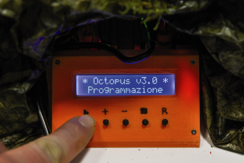
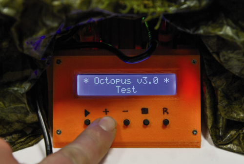
The user interface is presented by a 2-line, 60-alphanumeric-character LCD display with an I²C interface applied and a 5-key keypad allowing to select the tone to be reproduced and also to calibrate the servos and execute a pressure check test on the key. The headers are connected to five keys, as below:
Mem/PLAY -> 2- pin
Plus -> 8- pin
Minus -> 6- pin
Exit/STOP -> 3- pin
R -> Fishino reset/reboot pin
While the display is wired this way:
SDA display -> SDA
SCL display -> SCL
Vcc display -> 5V
GND display -> GND.
In this case, also, the pins are those from the headers. Using a display with I²C interface allows limiting the number of pins used on the Fishino Uno board.

Here you can see how we created the control panel of our system, which was then placed in the back of the assembly, just below the control electronics composed of Fishino Uno in the Octopus shields.
Mechanical section
After taking a look at the electronics part of the project, let’s get to the mechanics, which is equally important because it is the actuation section physically operating the keys.
The whole structure necessary to sustain the 24 tentacles and host the just as many servomotors (each one equipped with an arm screwed on the small shaft using the provided screws), and the electronic boards (i.e. the frame…) has been designed using Google SketchUp and 3D-printed using PLA; the actual frame can be printed using the STL file. Then, you have to apply the metal details on the frame which are needed for assembling the various parts such as the tentacles fulcrum; more precisely, the frame is made of several parts (edges, lower junction element, front cross piece…) to be screwed together.
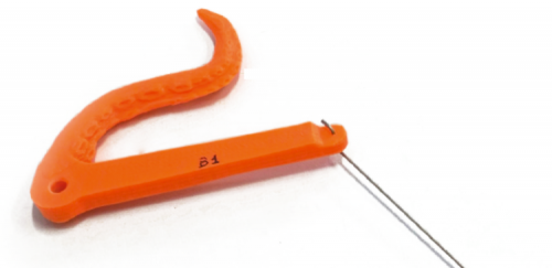
Each servo activates a tentacle (this also has been 3D printed and the STL file is available on our website along the other file for the project) through a conveniently shaped rod obtained by straightening a 0.9 mm stainless steel wire. The wire is then bent over in order to attach both on the servo shaft end and on the home provided for the corresponding tentacle.

Tentacles can sway in order to follow the movement imposed by the servos; for this purpose, each tentacle, placed side-by-side with the others, is hinged on a 4 mm metal rod.
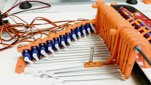
Length of the rods is not the same but must be determined in each case based on the distance between the servos arm and the base of the actuation lever of the corresponding tentacle, where all the mechanics on one side is shown (the right part of the servos and the corresponding support is missing).

This figure shows the details of how the rods attach to the base of tentacles, the prototype photos can explain better than anything how the mechanical structure is assembled which, once finished, must be mounted near the keyboard, on the front side, so that each tentacle can press one of the keys.
Since it is possible that the keyboard will move around during the operation due to pressure applied by the tentacles, it is recommended to attach the frame to the keyboard itself, for instance, you can use some right-angled metal strips attached to the bottom of the musical instrument, or you can place and screw the mechanical section to a wooden or plastic base plate (e.g. Forex…) and, once determined the optimal position, attach it to the keyboard with conveniently 3-D printed small square that are going to be screwed on the baseplate.

Key functions
Alright, now that we have also described the mechanical part, we can see how to use it and therefore how we can play our special instrument. Below, we describe keys functioning.
- Mem/PLAY: it allows to start execution of the tone in the position displayed. If held when turning on, it allows entering in “servo position setting mode”.
- Plus: it allows to move to the next tone. In “servo position setting mode” it allows modifying the tentacle position in order to press the key more or less. If held when turning on, it allows entering TEST mode.
- Minus: it allows to move to the previous tone. In “servo position setting mode” it allows modifying the tentacle position in order to press the key more or less. If held when turning on, it allows entering TEST mode.
- Exit/STOP: it allows to interrupt tone execution. If pressed in “servo position setting mode” it allows to exit that mode and go back to the main screen.
- R: it allows to reset and/or reboot the system.
Reset of all servos’ positions
Before activating the control lever related to the tentacle on the pivot of each servo, we have to place all the servos at half run (central position, -90°); this operation is necessary in order to make sure that once the servos are brought to zero, all the arms are in resting position. In order to reset position of all the servos, we have to press and hold the Exit/STOP key and then power on; the display will show the message “reset in progress”, after that all the servos’ pivots will get in central position and the display will show “reset successfully”. Now release the key. After that, apply the respective lever on each pivot so that the related tentacle will stroke (without pressing) the corresponding key.
Programming mode
Now, let’s take a look at how to program pressure position of the key corresponding to every single tentacle. Each servo must be assigned a position that allows pressing the signed key. In order to make all the necessary settings, we have to follow the procedure below.
1. Turn on the keyboard, press and hold Mem/PLAY key and then power on; the display will show the message “programming”.
2. Release the key. The interest server will be the first from the left (the first note of the first octave); the display will show the message “programming servo n°1”.

3. Press the + or – key so that the related tentacle will push on the corresponding key just enough to play the note. Once done, press Mem/PLAY key once again to move to programming the next servo.
4. When you reach the last servo, press Mem/PLAY key to end programming (the display will show the message “Programming Complete”).

System TEST
Now you have the check if all the tentacles correctly press the assigned key, in order to do so you have to:
- Turn on the keyboard, press and hold the + or – key, then power on; the display will show the message “Test”.
- Release the key.
Now, the tentacles will be activated in sequence, from left to right, in order to verify correct pressure of all the keys assigned. At the end of the test, the system will go back to the mainstream “Track selection”.
Track selection/ PLAY / STOP
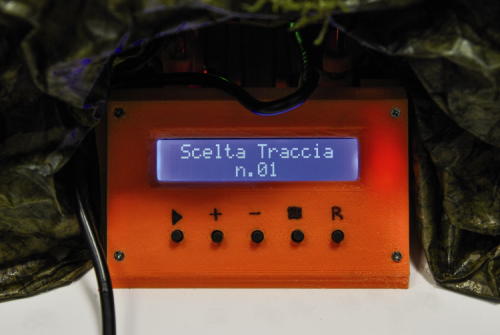
When the system is on standby, the display will show the message “track selection” followed by the actual track number (of the ringtone). In order to start execution of the track, press PLAY (the display will show for instance “Play track n° 1); to stop reproduction press STOP.
Firmware
We are going to end this article by mentioning the firmware, where you will find the ringtones to play and the instructions to do so. We are talking about the actual RTTTLs; the system provides for 30 ringtones to be played: this is defined in the instruction int Tracce_Max = 29; in the sketch initialization. Please note that 30 corresponds to the value 29 because we are starting from 0. By editing this value, you can edit the max number of ringtones you can play.
Each melody is made according to the RTTTL standard which calls for the definition of each note with related duration, with a comma separating it from the previous and the next one. Typical string format is:
const char PROGMEM MusicSongPlay1[] = “wewish:d=4,o=5,b=140:d,g,8g,8a,8g,8f#,e,c,e,a,8a,8b,8a,8g,f#,d,f#,b,8b,8c6,8b,8a,g,e,8d,8d,e,a,f#,2g.”; this refers to execution of wewish ringtone, composed by the notes defined by the letter with the comma, followed by =, and duration, therefore d=4, o=5, b=140 etc. (d is duration, o is the octave and b are the beats). Please note that these instructions can be composed by writing them in Arduino’s IDE, or you can directly copy them from ringtone websites since these are provided with the same syntax.
Generally, those websites provide files that can be opened with a text editor (they are .txt files); in order to write the music all you have to do is copy the specific text string and paste it in Arduino’s IDE editor.
In the sketch, each note is defined by the instruction:
#define NOTE_C4 262
Which specifies the position of the servo to be activated in order to press the corresponding key on the keyboard.
For what concerns shields routing, the Octopus.h library is preset so that outputs 0÷15 refer to the shield labeled as 0, and 16÷32 outputs refer to the shield labeled as 1, etc. Therefore, before applying the shields to Arduino or Fishino you have to set the address jumpers of the first shield as 000 and the second ones as 001, otherwise, correlation between notes and servos established by the firmware will not be respected.
The sketch for Arduino/ Fishino is quite bulky and, we cannot quote it here due to space available; you can find it and download it from the download section of our website, along with the other files for the project.
Very well, this concludes our article; possible developments and customizations are left to your imagination.
From OpenStore
