It is open source and based upon the ATmega32U4 microcontroller, and provided with drivers for two DC brush motors and a stepper motor. It receives commands via USB or serial ports, or via the I²C bus.
For those dealing with robotics, one of the problems to solve is the management of the motors used for the traction, that is to say: how to correctly power the motors needed in order to make your robot advance. If you work with Arduino, the first and immediate solution is to use a shield. Several of them can be found available for sale, from the simplest ones that allow to control separately the two small DC motors, to the most advanced ones that are able to measure the current drawn as well. Regardless of the manufacturer, the shields are all based on the usage of a power driver (usually the L298), that is directly interfaced to Arduino’s PWM outputs, and encircled by a few other components. Surely the usage of a shield is a valid solution, but then we need to use at least four Arduino outputs: usually two to adjust the speed and two for the direction. If, on the other hand, you use a generic microcontroller, or a stand-alone Atmel chip, or a board that is different from Arduino, things get a bit more complicated, since on the market it is difficult to find drivers with a more flexible interface, and the price starts to rise quickly. If you then have the need to command two motors, things get very complicated, even for those using an Arduino board, because problems arise both on the hardware and on the device programming point of view.
To meet the needs of those who want to manage small DC motors and having programmable logics, we thought to design our own driver, to allow for a high operating flexibility and above all, that it would be open source, in order to let anyone adapt it to his own needs.
The name we gave it is meaningful of the project philosophy: OpenMotorControl, that we shortened in OMC21, with 21 indicating the number of channels (two in this case) and the current being managed for each channel (1A).
As we will see, it is a stand-alone circuit that can be driven by various logics, provided with a communication interface that takes different communication protocols into account and that is suitable for the most different needs.
Circuit diagram
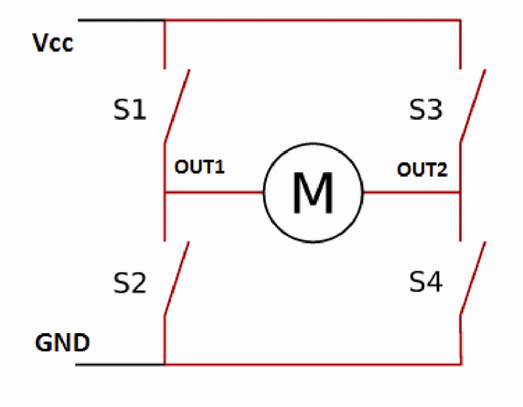
Typically, to create a controller for direct current motors, people rely on the so-called H bridge, that is to say, a circuit formed by four transistors in a bridge connection, and capable of commanding the motor’s speed and direction by means of the PWM pulses being supplied, and of the polarity being inverted at the output.
Such a driver can be found in a monolithic form in various integrated circuits; only in particular cases, as it was on the Openwheels control board (a self-balancing vehicle project, published starting from the installment n° 172) it makes sense to design a similar driver with discrete components.
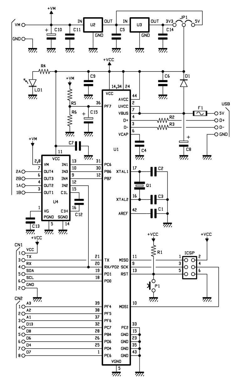
For our application, a simple and cheap integrated circuit containing a H bridge will be more than enough, also because it allows to limit costs and encumbrance. The integrated circuit we adopted is signed LV8405 and is a complete high performance MOSFET H bridge that implements a voltage power control and is supplied with protections, both for temperature and current. It is sold with the SMD SSOP16 package and thus it cannot be used directly in a breadboard, but it must be taken into account by a dedicated PCB. Even if very small, it has remarkable features:
- 2 channels having forward/reverse control;
- low energy consumption;
- MOSFETs’ series having low resistence (0,75 ohm);
- integrated protections from low voltage and overheating;
- four operating modes (forward/reverse, brake, stop);
- maximum output current: 1,4A;
- output current (as a peak): 2,5A.
The very low resistence of the MOSFETs used for the motor’s control (only 0,75 ohm) allows for a very high performance and sports a very limited heat dissipation.
To create a motor control that is easy to interface and program, it is however needed to couple this IC to a duly programmed microcontroller: the choice fell on the ATmega32U4, manufactured by Atmel: the same used by Arduino Leonardo board. Unlike Arduino Uno that has the ATmega328 microcontroller, the ATmega32U4 is used in the Leonardo board, since it internally implements all the hardware needed for the USB communication, thus eliminating the need to use a USB/serial converter, externally. The features are usually better than those of the ATmega328, since it is a last generation component; moreover the microcontroller is perfectly compatible with Arduino’s development environment (IDE). A few more components and here we have at our disposal a small, cheap motor control, one that has interesting features:
- double H bridge configuration, needed in order two drive to DC motors or a bipolar stepper motor;
- power section’s voltage: 3 ÷ 15V;
- logic power supply voltage: 3 ÷ 5V;
- output current: 1,4A direct current (2,5A as a peak) for each motor;
- interfacing via USB, serial, I²C-Bus communication;
- compatible inputs at 3,3V and 5V;
- selectable power supply modes: internal and external at 3,3V or 5V.
Since we wanted a very flexible controller, we looked after the power supply section in particular; we wanted a driver that could be compatible with logics operating at 3,3V and 5V, one that could be powered by the same voltage of the command logic, and that could power an external logic, so to work with the same power supply levels.
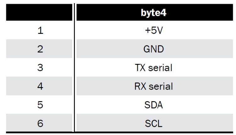
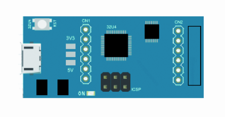
As you can see from the circuit’s diagram (you may find it nearby…), two low-drop-out voltage stabilizers (a low input-output voltage drop) have been taken into account: they are used to obtain the power supply voltages at 3,3V (U3 deals with it) and 5V (U2 deals with it). The selection of the power supply voltage needed happens by joining the corresponding holes of the JP1 jumper with a drop of tin. By welding the central hole with the 3V3 one, the power supply voltage is set at 5V, while connecting it to 3V3 the voltage is set at 3,3 volts. As per specifications of the ATmega32U4 integrated circuit, the operation at 3,3 volts is guaranteed only with a 8MHz quartz, to which a corresponding bootloader has to be coupled. The selected voltage is also available on the CN1 connector and can be used to power an external logic, as an Arduino board (please see Table). The main power for the whole circuit is drawn from the power supply line of the VM motors.
Another possibility takes into account that we might not weld any CN3 connector’s hole, in this way the VM power supply will be used to power the motors only, while the power supply for the ATmega32U4 will have to be applied externally, from the command logic, via the CN1 connector; in this case it is needed that the command logic is powered separately.
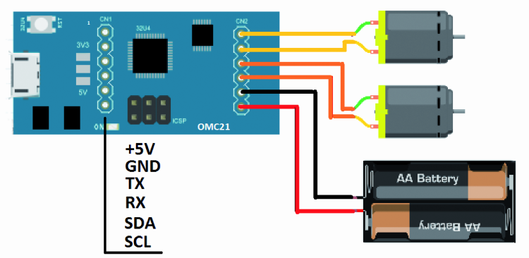
As regards the power supply connector, it takes six contacts into account: of them, two are used as power supply and are named VM and GND, two are used for the first motor (1A and 1B) and as many for the second one (2A and 2B). The VM power supply will obviously have to be compatible with the motors’ power voltage and will have to supply enough current to power the motors. The ICSP connector is the one used for programming: later we will explain how to use this connector to load the bootloader in the ATmega32U4.
CN1 is the connector used for the logic and for the serial and I²C communication. As for the micro USB connector, it is used both for giving commands to the controller, and for the microcontroller’s programming via Arduino’s IDE.
To load the bootloader you will have to necessarily proceed like this: don’t connect anything to the CN2 connector and leave the connector used for the power supply selection unwelded, or keep a 5V voltage setting. If you have a dedicated programmer for Atmel devices at your disposal, you will already know the procedure; otherwise please equip yourselves with an Arduino Uno board, that you will use as a programmer.
The OMC21 controller’s ICSP connector will have to be pin-to-pin wired to Arduino’s ICSP connector that is used as a programmer: that is to say, pin 1 goes with pin 1 and so on. The Pin 5 (the reset pin) of the controller’s connector, that we have to connect to Arduino’s pin 10, is an exception. At this stage we may connect the Arduino board to the USB port; the OMC’s power supply LED will turn on to indicate its proper power supply.
Please load the Esempi-ArduinoISP sketch on Arduino, it will enable Arduino to operate as a programmer; now open the Strumenti-Tipo di Arduino menu and modify the programming target in Arduino Leonardo. Please select the Arduino as ISP programmer and then boot the bootloader programming by clicking on Scrivi il bootloader. Please wait for about a minute for the operations to be completed.
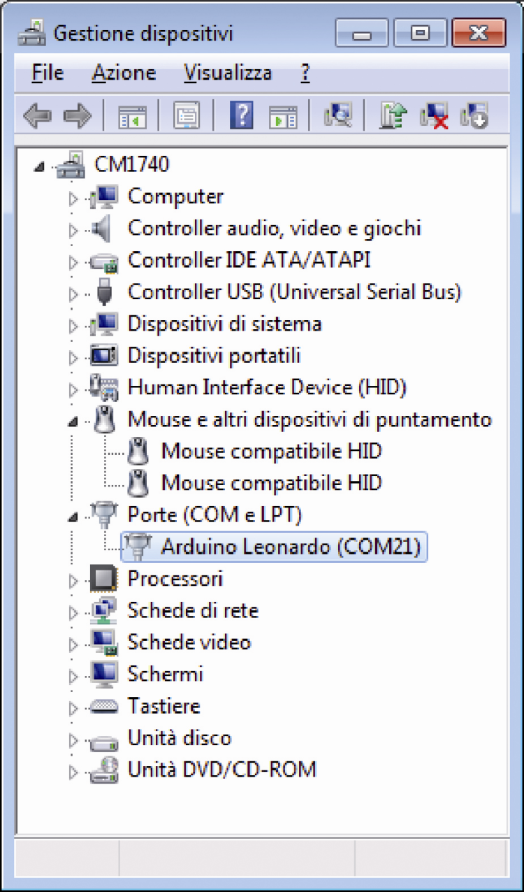
The ATmega32U4 integrated circuit has a main serial port that depends on the internal USB module; at a programming level nothing changes in comparison to Arduino, if not for the fact that a USB/serial converter is not needed since it has already been implemented inside it. Thanks to the bootloader, as soon as the OMC21 is connected to the USB port it will be recognized as a peripheral and a virtual serial port will be created: it will be labeled as Arduino Leonardo and a name will be given to it: in the case of the figure, it’s COM21.
At this stage your OMC21 can be completely managed via USB and it is possible to load (by means of Arduino’s IDE) the management sketch named OMC21.ino; let’s describe now how this management software operates, in particular as for the H bridge’s control. Let’s start by saying that the management of the four static switches represented by the transistors can be carried out in different ways, depending on the function we want to obtain. Let’s take figure as a reference: in a simplified way, it represents the H bridge’s four switches that have been implemented by means of MOSFETs in our driver.
Let’s read carefully the LV8405V-D driver’s data-sheet in order to obtain the truth table concerning the switches’ (S1-S4) and outputs’ (OUT1 and OUT2) state, for each possible input combination; the letter L indicates a low logic level, while the letter H indicates a high logic level.
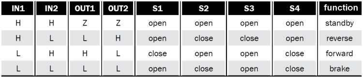
By analyzing table it is possible to understand the different operating modes more in depth, depending on how we steer the two inputs: IN1 and IN2. In the first case (IN1=H and IN2=H) both outputs will be in a high impedance state; in such a situation it is as if the motor was disconnected from the driver, and free to rotate. If on the other hand we consider the fourth case (IN1=L and IN2=L), it is as if the motor was in a short circuit state; what does it change between the two cases, in practice? If we use the motors to advance a robot that is moving forward at a high speed, in the first case, by depriving the motors of the power, we will obtain a gradual stop of the robot, that will halt itself in a space depending from its inertia. The stop will depend from the various frictions within the mechanical units and from those between the robot and the surface it is moving on. To understand what will happen in the second hypothesis, we need to consider that a direct current motor is a reversible machine, that is to say, if we supply power to it its motor will rotate, but if it is us to rotate the motor it will supply power, thus acting as an electric generator; in this second case, due to the armature reaction, the effort required to rotate the axle will depend on how much power is drawn from the ends of the motor’s windings.
By transferring this idea to our case, we may say that when the robot is moving we take away voltage from the motor, and the latter will continue to turn because of inertia, but if the bridge short-circuits its terminals, the current originated from it and within the winding will in turn cause an electromagnetic field, so as to oppose the cause that generated it; and since this cause is the axle rotation, the latter will be slowed down until it stops, while if lacking the current, the braking action will stop as well. If you try both cases, even only by making a wheel move by means of your hand, you will notice the effect in practice. In many commercial shields these two functions cannot be selected, while for our circuit we enabled the possibility to select (via software) the mode with which to use the outputs.
The two remaining cases that have been described in previous table, on the other hand, are easier to understand: if we set the IN1 input at a low level and command the IN2 input by means of a PWM signal, we have the possibility to command the motor to go in the forward direction, with a power that is directly proportional to the duty-cycle value, which allows to regulate the robot’s speed (when the duty-cycle reaches zero, the robot will be stopped with the braking effect we previously described). If on the other hand we applied the PWM signal to the IN2 input, but we set the IN1 input at a high level, when the duty-cycle reaches its maximum value we find ourselves in the case of the high impedance outputs, and the robot will stop without any braking effect.
By inverting IN1 with IN2 we will have the same functions, but with the motor rotating in the opposite direction. You will see then how, by operating on the inputs, we have the possibility to choose the motor’s direction and speed, and to activate or not the braking effect.
The IN1 and IN2 inputs, that are the driver’s inputs for the first motor, and the IN1 and IN2 inputs for the second motor, are connected to four ATmega32U4’s PWM outputs, that can be easily manage by means of the analogWrite instruction that is available with Arduino’s IDE. The CN2 connector has been designed for the motors’ connection and for the power supply: on it both a male or female strip can be welded, plus a connector having screw clamps. We also allowed the possibility to read the VM supply voltage by means of a simple voltage divider; to make the motors’ supply voltage level compatible to the reading one of Arduino’s analog inputs, the voltage is reduced by 11 and thus made available at Arduino’s A0 input. Knowing the voltage allows, in the case of battery power being used, to avoid a complete discharge, that is to say, to avoid the over-discharge (which is always detrimental) when loading. Further Arduino pins depend on the CN2 connector, that is to say the remaining digital pins that have not been used by the driver, and three analog pins. In practice, it is as if we had an Arduino Leonardo board having a motor driver onboard.
The firmware
Let’s deal now with the description of the program that will be loaded on the ATmega32U4. The sketch will have to deal with the management of the USB, serial and I²C communication, by understanding the commands read and by putting them into practice, by adequately commanding the driver’s inputs. The sketch considers then a listening routine on the three communication ports, while waiting for the data to arrive; luckily the small ATmega32U4 has two UART modules and a I²C hardware port, and they are perfect for our project. The main serial (Serial) port depends on the USB module and from the software point of view it behaves exactly like Arduino Uno’s serial port, thus the data reception of the on this port may be obtained by means of the Serial.available() instruction, that refers the number of characters found on the reading buffer. In this mode, OMC21 can be controlled via a PC or any other peripheral having a USB host. This serial communication’s usage declaration is made by means of the Serial.begin(9600) code line, with 9600 being the communication speed (which can be modified, depending on your needs). We used 9600 as a default setting since it is the most used speed; if you want to reduce the commands’ reading time, you may increase this value up to a maximum of 115.200 bps. If there are characters in the UART module’s buffer, they are read by means of the Serial.readBytes(inByte, maxinByte) instruction, that enables the reading of a predetermined amount of bytes in a prearranged time interval. The communication protocol we thought to use takes into account that four bytes will be used, the first one being the ‘$’ character only, which is needed to recognize the beginning of the sequence. Along with the number of characters sent, it represents the accuracy control when reading the command. Once the reading of the four bytes has ended, there is a check to verify if there are more; in any case the buffer is emptied. It may happen that by sending commands some unnecessary characters are added, such as an end of line or a return; in our application those are ignored and deleted from the buffer. The three remaining bytes (after the ‘$’ character) represent the controller’s commands: the second byte contains information concerning the operating mode (brake or standby) and on the motors’ direction of travel, while the third and fourth bytes contain information concerning speed, for the motors 1 and 2 respectively. In this way, by sending a four bytes sequence, both motors can be commanded at the same time.
![]()
Byte2 contains information concerning both the operating mode and the direction of travel. Byte2’s fifth bit, if set at one, enables the request of the power supply reading; this is the only case in which the bidirectional serial communication is needed, otherwise just the line concerning the data sent to the controller is enough.

In Listing 1 you will find the sketch’s code lines that develop the described functions. If you want to command the controller by means of the microcontroller’s serial port, you will have to use the second serial port (Serial1) of the ATmega32U4 microcontroller, whose TX and RX pins are available in the CN1 connector.
Listing1
if(Serial.available() > 0)
{
char inByte[maxinByte];
int numByte = Serial.readBytes(inByte, maxinByte) ;
//reads until maxinByte are reads or if TimeOut is occurred
byte extraByte; // clear the buffer if extra bytes is arrived
while (Serial.available())
extraByte = Serial.read();
//if data starting with ‘$’ and lenght is correct...
if (inByte[0]==’$’ && numByte==maxinByte)
{
dirM1 = inByte[1];
dirM1 = dirM1 & 0x01;
dirM2 = inByte[1];
dirM2 = (dirM2 & 0x02)>>1;
modeM1 = inByte[1];
modeM1 = (modeM1 & 0x04)>>2;
modeM2 = inByte[1];
modeM2 = (modeM2 & 0x08)>>3;
speedM1 = inByte[2];
speedM2 = inByte[3];
setMotor();
byte readVM = inByte[1];
readVM = (readVM & 0x10)>>4;
if (readVM==1)
{
int VM = analogRead(VM_pin)*36;
VM = VM>>6;
Serial.println(VM); //VM*10 [volt] (0-255)
}
}
}
The connection takes into account that the microcontroller’s TX line is connected to OMC21’s RX line and, if the reading of the voltage supply is requested, that the microcontroller’s RX line is connected to OMC21’s TX line as well. The code line that enables this serial port is Serial1.begin(9600); even in this case the communication speed can be set up to a maximum of 115.200 bps. As for the rest of the management from the point of view of the software, it is the same of the main serial port. As for the I²C communication port, it is enabled by means of the Wire.onReceive(I2CreceiveEvent) instruction, in which the I2CreceiveEvent label indicates the procedure recalled by the interrupt, when the first byte arrives. Please refer yourself to the Listing 2, for the particulars concerning the processing of the data received.
Listing2
void I2CreceiveEvent(int byteIn)
{
while( Wire.available()>0) // loop until available byte on wire
{
char acknowledge = Wire.read();
if (acknowledge==’$’)
{
char mode = Wire.read(); // read mode byte
speedM1 = Wire.read(); // read speed byte
speedM2 = Wire.read(); // read speed byte
dirM1 = mode;
dirM1 = dirM1 & 0x01;
dirM2 = mode;
dirM2 = (dirM2 & 0x02)>>1;
modeM1 = mode;
modeM1 = (modeM1 & 0x04)>>2;
modeM2 = mode;
modeM2 = (modeM2 & 0x08)>>3;
setMotor();
}
}
}
For each data arrived on this port, a procedure is recalled: it deals with checking if the sequence is compatible with the OMC21 standard, and then extracts its values. The sketch for OMC21 is thus prearranged to continuously monitor the transmission of the command bytes on the three communication ports: USB, serial and I²C. The port on which the data will arrive is unimportant, and at most they could even arrive at the same time, though if would be quite useless to do it; the advantage is anyway that of loading a single sketch, thus avoiding to go nuts because of programming. Once programmed, our OMC21 controller is ready to activate the motors, depending on the commands received: let’s see how to do it by means of some examples, by taking advantage of the various communication ports.
Management via USB
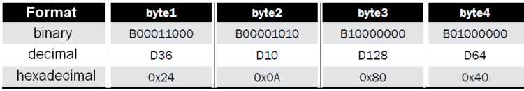
As soon as it is programmed, OMC21 is still connected to the USB port and immediately one may have an urge to test it without further wirings, by using the PC to send commands. As an example, let’s see how to build the three data bytes for the motors’ control, in the case we wanted the motor 1 to go in a forward direction with 50% power and braking function activated, and the motor 2 to go in the reverse direction with 25% power without braking (standby). Since the speed is expressed as a numeric value between 0 (0% power) and 255 (100% power), the two values, 50% and 25% correspond respectively to the decimal values 128 and 64. Byte2 will have to be built, bit by bit, as shown in table.

The three command bytes will then be the ones shown in table .
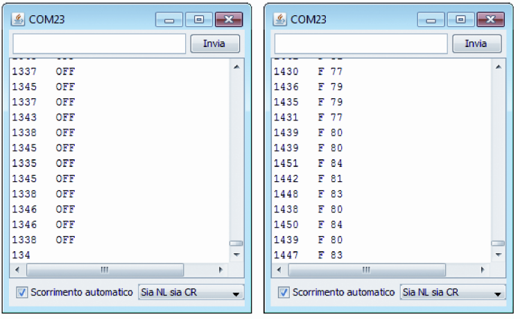
If our controller is connected to the serial port, we will hardly control it by using Arduino’s SerialMonitor function, for the simple reason that the first 31 ASCII code characters cannot be printed, since they are used as commands with regard to the communication with printers. If we want to send the four so-built bytes, it is needed to use a serial monitor that enables the management of the characters that cannot be printed as well; in our case we used a free software, distributed in a portable version and named SSCOM, but there are many others available on the Internet. In the example the bytes 0x24 0x10 0x8F 0x00 have been sent (red circle) and they correspond to the stopped motor 1 and to motor 2 going forward with 56% power, and to a request for the VM supply voltage.
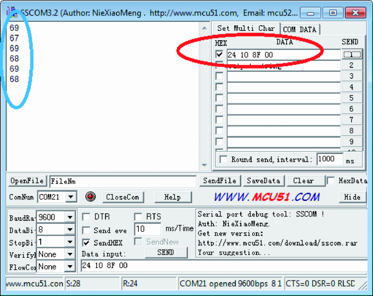
The response data regarding a supply voltage of about 6,8 volts is highlighted in blue. If, on the other hand, you want to create your own management software, we advice using Processing, that will allow to easily use a serial communication via USB: a sample sketch is found in Listing 3. In this example, an item of the serial class is simply created, then at the start of the sketch the port is opened and, as soon as any point is clicked, the four bytes are sent, as needed by the OMC21’s command. Since there is no drop down menu to choose the COM port from, it is specified by means of the portName = Serial.list()[0] code line, in which we need to indicate the index corresponding in the list of the COMs that are installed on the PC. If you do not have any COM hardware and Arduino alone is connected to the PC, as it often happens, in the list you will find a single COM whose index is zero.
Listing3
// OpenMotorControl21
// Example to use Processing for control OMC21 USB
import processing.serial.*;
Serial myPort; // Create object from Serial class
void setup()
{
size(200,200);
background(0);
String portName = Serial.list()[0]; //change the 0 to a 1 or 2 etc.
println(“portName: “, portName);
myPort = new Serial(this, portName, 9600);
}
void draw()
{}
void mouseClicked() // if click on background
{
int dirM1 = 0; // set direction for Motor1 0=forward 1=reverse
int dirM2 = 0; // set direction for Motor2 0=forward 1=reverse
int modeM1 = 0; // set mode for Motor1 0=brake 1=standby
int modeM2 = 0; // set mode for Motor2 0=brake 1=standby
int mode = (modeM2<<3) + (modeM1<<2) + (dirM2<<1) + dirM1;
char modedir=char(mode); // convert integer to char
char speedM1=128; // set speed for Motor1 at 50%
char speedM2=128; // set speed for Motor2 at 50%
myPort.write(‘$’); // write start char
myPort.write(modedir); // write mode-dir byte
myPort.write(speedM1);
myPort.write(speedM2);
}
Management via Serial communication
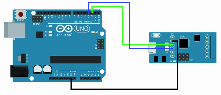
If we wish to command OMC21 by means of an Arduino board, it is convenient to use a software serial communication, by using a single digital line to connect to the CN1 connector’s RX line; in this way the hardware serial port will be free to communicate with the PC.
The sample sketch can be found in Listing 4, where it is shown how it is possible to build the control byte (byte2) by starting from the settings of the single bits for direction and braking. It will be the int mode = (modeM2<<3) + (modeM1<<2) + (dirM2<<1) + dirM1 a code line to rebuild the complete byte, by moving and adding the single bits. At a later stage we will use the four Serial.write commands to send the single bytes containing the start character and the three data bytes.
Listing4
// OpenMotorControl21
// Example to use Arduino for control OMC21 Softserial Serial
#include <SoftwareSerial.h>
SoftwareSerial OMCSerial(2, 3); // RX, TX
void setup()
{
Serial.begin(9600); //use Hardware Serial to communicate with PC
OMCSerial.begin(9600); //use software serial to communicate with OMC21
}
void loop()
{
byte dirM1 = 0; // set direction for Motor1 0=forward 1=reverse
byte dirM2 = 0; // set direction for Motor2 0=forward 1=reverse
byte modeM1 = 0; // set mode for Motor1 0=brake 1=standby
byte modeM2 = 0; // set mode for Motor2 0=brake 1=standby
byte mode = (modeM2<<3) + (modeM1<<2) + (dirM2<<1) + dirM1;
mode = mode+16; //if request Motor voltage
char speedM1=128; // set speed for Motor1 at 50%
char speedM2=128; // set speed for Motor2 at 50%
OMCSerial.write(‘$’);
OMCSerial.write(mode);
OMCSerial.write(speedM1);
OMCSerial.write(speedM2);
delay(1000);
}
Management via I²C communication
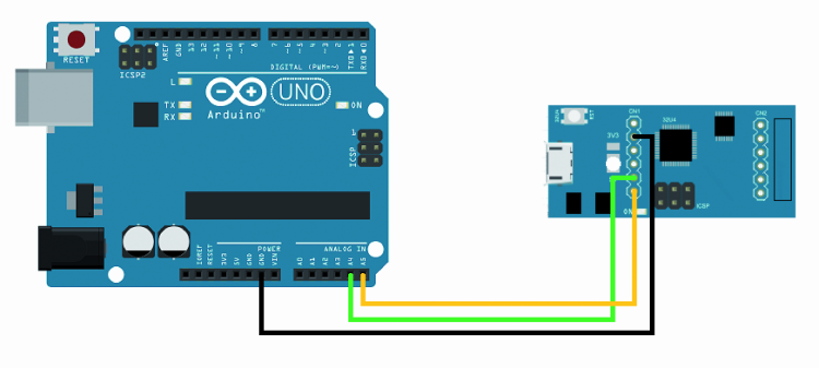
If you want to control OMC21 by means of Arduino’s TWI port, you just have to connect the two lines (SDA and SCL) between them for both ports, and to connect the GNDs for both boards. Pull-UP resistors are not needed for the simple reason that they are already inside the microcontroller, both in Arduino Uno and in the ATmega32U4, and they are automatically enabled, once the Wire.begin() function is recalled.
The sketch to command OMC21, to be loaded in Arduino Uno, is found within Listing 5, that appears to be very similar to the previously described listings. There is however an important difference with the way of communication by means of serial port, concerning the peripherals’ addressing system. While in a serial communication the data exchange happens point by point, that is two say only two peripherals interact between them, in the I²C Bus up to 127 Slave peripherals may coexist, and they are all communicating with the only master unit. The master unit in this case is Arduino Uno (or the command logic), while the slave units are the OMC21 boards; the obvious advantage is that more controllers and thus more motors can be used, and they are all managed by a single Arduino board, by using a single TWi port.
We would like to remind you that, for all intents and purposes, in Arduino the TWI port uses the I²C protocol, that is a Philips proprietary one (since they created it).
Listing5
// OpenMotorControl21
// Example to use Arduino for control OMC21 I2C
#include <Wire.h>
const int OMC21address=4; //address of OMC21
void setup()
{
Wire.begin(); // join i2c bus (address optional for master)
}
void loop()
{
byte dirM1 = 0; // set direction for Motor1 0=forward 1=reverse
byte dirM2 = 0; // set direction for Motor2 0=forward 1=reverse
byte modeM1 = 0; // set mode for Motor1 0=brake 1=standby
byte modeM2 = 0; // set mode for Motor2 0=brake 1=standby
byte mode = (modeM2<<3) + (modeM1<<2) + (dirM2<<1) + dirM1;
char speedM1=128; // set speed for Motor1 at 50%
char speedM2=128; // set speed for Motor2 at 50%
Wire.beginTransmission(OMC21address); // transmit to OMC21
Wire.write(‘$’);
Wire.write(mode);
Wire.write(speedM1);
Wire.write(speedM2);
Wire.endTransmission(); // stop transmitting
delay(1000);
}
In fact, in Listing 5 the const int OMC21address=4 code line can be found: its aim is to specify the slave towards which the communications happens; obviously other slave units as well may coexist on the TWI BUS, and they don’t have to necessarily be OMC21 motors. In the OMC21.ino sketch the specified value for the peripheral default address is 4, but it may be modified at leisure, if you want to use a peripheral on the bus, and it already has this address.
If more OMC21 controllers are used, it is needed that each one of them has an univocal address; thus you will have to load a sketch on which a different address has been specified, on each controller. While writing the control program you will have then to keep in mind the various addresses that have been assigned, in order to assure the proper data transit.
Controller’s usage
As for the connections and the practical usage, many combinations are possible as regards the power supply for the control logic and the LV8405V-D integrated driver’s power section; In figure shows the general connection of the two DC motors (as for the bipolar stepper-motor, each winding goes in the place of a motor) and of the board power supply.
On the other hand illustrates how to set up the 3V3/5V jumper (in this case we have to leave it completely open), used for the power supply selection concerning the microcontroller and the LV8405V-D driver’s logic, so that it is directly drawn from the USB connection; in the same picture the motors are powered via VM.
This figure shows how to set the jumper if you want to power the power circuit by means of VM, and the microcontroller and the driver’s logic via the 3,3 volts obtained from the same VM, by means of the U3 regulator (the jumper has to be created, taking care to close it with a tin drop).

In figure we propose a jumper’s setting, having the microcontroller and the driver’s logic powered with the 5 volts that the U2 regulator obtains from VM (circuit input voltage and power voltage).

Let’s come to the point of Arduino Uno’s connections for the serial control: in the followinf figures regard the connection respectively via the TTL serial communication and via the I²C-Bus. Let’s give now some advice for the proper usage of this controller, taking into account all the problems that we may encounter in practice, when using brush motors.
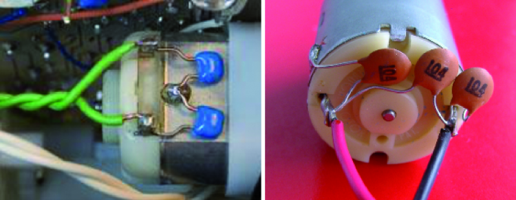
Before connecting a motor, it is a good practice to verify if the maximum current absorbed (usually called stall current) does not exceed the maximum allowed value. Another good practice is that of welding the three ceramic capacitors (having a value between 10 nF and 100 nF) directly on the motor’s contacts, for the purpose of suppressing the noise coming from brushes rubbing on the collector. The capacitors have to be welded between the two terminals and the frame, and possibly also one of the two power supply terminals.
To close the article, we wil also refer a practical example concerning our controller’s usage: we will use it to substitute the broken electronic circuitry of a small RC car. In this example we use OMC21 to read the signals coming from a RC receiver (one of those being used in the field of model building), and to command the car’s motor. The receiver is powered by the same OMC21, thanks to the internal voltage stabilizer, set at 5V. The servo for the steering wheel is directly controlled by the RC receiver. The power supply comes from a small LiPo battery, directly connected to OMC21. The program to install on the controller is named esc_rc_car2.ino and also takes a diagnostics function into account, thanks to which it is possible to see the data received from the RC receiver on the serial monitor.
The program is a very simple one, and it is based on the reading of the duration of the pulse received from the RC receiver, thanks to Arduino’s pulseIn function; from this reading it is then sufficient to obtain the exact value of the duty-cycle for the motors’ command. As for the rest, the functions that have been previously described have been used, with the addition of the battery voltage’s reading, with the setting the motor’s turning off (cut-off), as soon as the voltage goes under 6V, in order to protect the battery used as a power supply.
From openstore
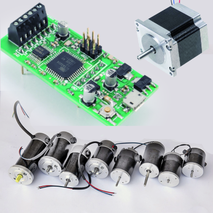
Stepper motor NEMA17 – 1,8° – 2,5A
Stepper motor NEMA23 – 1,8° – 2,5A

Hey thank you for sharing the article. Nice explanation.
I need to command two motors with those stepper motor driver purchased:
http://blog.poscope.com/stepper-motor-driver/ Any suggestions where could I find manual for that?
There is a problem with the code listings in the article. Some of the characters have been converted to HTML character entities.
For example in Listing5 where you include the Wire library it should say:
#include
Instead it says: #include <Wire.h>
The the ” were replaced with < and > respectively. If someone copied that code it would not compile for them.
Thank you, I fixed
[…] [source: http://www.open-electronics.org] […]
[…] [source: http://www.open-electronics.org] […]