It allows controlling devices such as lights, motors and even relays from a channel of a radio modelling receiver.
The signal and the standard of servo controls were born to guarantee proportional control of utilizers such as electric motors for modelling and radio modelling, in order to set and maintain a well-defined angular position of the small shaft in those. However, there are applications where an on-off impulsive or stable control would be desirable, to activate or deactivate a relay, power on and off a circuit and so on; for instance, in dynamic modelling, it would allow to turn on onboard lights or extract and retract the landing gear of a model aircraft. The on/off control is not really compatible with the proportional control of common modelling transmitters since it requires the simple presence or absence of a coded signal, instead of the length variation of an impulse. However, it is possible, with some small precautions, to use a proportional radio control unit to activate utilizers in on/off mode: it is basically about setting up the utilizer to stay idle up to a certain threshold (value) and then activate it at the preset threshold, or vice versa.
In this article, we are going to explain how to do it, by proposing a very simple circuit to this purpose.
In order to understand how to possibly obtain an on/off control starting from a servo proportional one, first we have to explain how the servo controls management used in radio commands works, whether for hobbyist radio controls or for remote-controlled exponential robots or service robots: in this kind of control, a rectangular signal is sent, which impulse duration determines the movement extension, i.e. the angle of the servo control are; if we are controlling motors, lights or other utilizes, the duration determines rotation velocity, light intensity etc.
The standard signal is shown in Fig. 1 and it has a typical frequency of 50 Hz, which means a 20 ms period.

Fig. 1
Set signal is, therefore, a sort of PWM with three well-defined duty-cycle values (the impulse, actually) corresponding to as many rotations on the servo control pivot: 1 ms, moving the pivot all to the left, 1.5 ms (pivot in the centre) and 2 ms, corresponding to maximum clockwise rotation.
The decoder inside the servo control or another device designed to respond to this protocol is capable of deciphering the signal and the duration of the related impulses.
Our circuit
Our solution, also available as a breakout board for quicker use and fast prototyping, calls for using a program microcontroller to decode impulses contained in the signal provided by the receiver of the radio control and, based on the set threshold, activate or deactivate a utilizer, which means controlling a relay tasked with managing the utilizer itself. Impulse decoding can be obtained by counting the time elapsed between their detection and the pin of the micro set as input and preceded, as shown in the circuit diagram, by a NPN transistor (Q2), which collector is capped at level high, in standby, by the pull-up resistor activated and the input paint on the micro.

The signal provided by the radio control receiver (comment on IN and GND) polarizes Q2’s base, which is in saturation in connection with the impulse (therefore brings the microcontroller’s input to logical zero), while it is in interdiction during pauses. The NPN works as level adapter since it accepts voltage levels that can be higher than 5 V on the base divider, while it provides, via its collector, suitable impulses for the microcontroller’s working voltage. The micro, using a dedicated timer, counts the duration time of the logical zero impulse, then if that is lower than a certain value (typically 1 to 5 ms, corresponding to standby position) it leaves RA2 output line in standby, on the other hand, if it is over the threshold, the above-mentioned output is brought at logical 1.
The OUT line, besides being brought on the side connections of the board, controls the gate of an N-channel, enhancement mode MOSFET (Q1) working as a static switch and configured therefore as open drain (low side) in order to pilot the utilizer (for instance, the coil of the relay) with its drain, in relation to the positive power line of the load, powered by 5 V. The switch also has a flyback (or freewheeling) diode across the activation outputs so that it is possible to connect a coil to one of those, e.g. a motor or a relay, without additional external components.
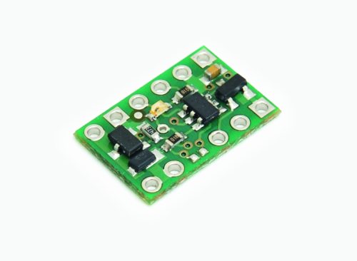
Fig. 2
If you want, since the load power (power applied between GND and the anode of the flyback diode) is selectable via a jumper, you can power that section with more than 5 V, in order to manage other types of utilizes.
Our circuit can be used with standard modelling radio controllers, as mentioned above, to act on computers or simple interface applications.
The GOOD output of the breakout board indicates the presence of a valid signal on the circuit’s input: when it receives a standard servo RC signal, that line is brought to a logic level high.
If you want to connect the board to a relay, to commute loads having the power you need, you must make all the connections shown in Fig. 3.
Controlling the switch through a dynamic modelling radio control can be done using the usual joysticks, or, for transmitters equipped with stable position keys or switches, through one of these, when appropriately configured. In that case, in order to set the channel to couple with the switch we are going to use on our radio control, we must proceed by following the manufacturer’s instructions. For our tests, we used an FS-i6S transmitter by FlySky designed for controlling plane models, where we just had to go to the settings from the touchscreen and select “Aux channels”, select our preferred channel and assign it a key.
Then, when connecting the pins labelled RC receiver on the board to the receiver on the selected channel, when we activate the switch, the RC switch will quickly blink and our relay will turn on.
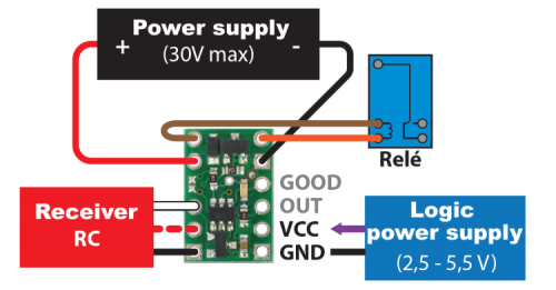
Fig. 3
Test AND use
Once installation is complete, you can use the board, and don’t forget to close the power jumper (JLO) if you are going to pilot a load or a relay using the MOSFET, powering it with the same Vcc used by the microcontroller, otherwise you can open it and power the board through the dedicated Vcc and GND pads if you want to supply a higher voltage than the one provided for the breakout board. In this case, the circuit including the load managed by the MOSFET must be powered by the desired voltage (however, never more than 30 V…) Using pads HI (power positive) and GND (negative) and the load must be connected between pads LO (negative) and HI (positive).
From openstore
Pulse converter Servo RC to Digital
