
Let’s create a new evolution for our 3Drag printer, with a dual extruder for the printing of chocolate items of two types or colours.
The 3Drag printer has been our answer to the growing need – on the part of the general public (a need that was already shown towards the RepRap project) – for an open, affordable and customizable 3D printer; it’s not by chance that this printer, born in the summer of 2012, gained fame as the “most hackable 3D printer in the world” in a short time. And this because it was born out of a completely open project. We showed that in time, by showing you how it may become a CNC milling machine, and also a printer of chocolate items. We then “stretched it out” so to have it print items having a greater size: and so the 3Drag Big was born. But the requests for the expansion of this project follow one another unrelentingly; those who tried the Choco printer kit showed their will to print chocolate items having more colours, or using different kinds of chocolate in a single step; from here the idea of creating a 3Drag Choco with dual extruder was born: we will describe it in this article.
Certainly, to create it wasn’t a task as immediate as designing it, since, given the size of the printhead, in order to mount two of them (with the power source mechanism as well) we had to keep the nozzles at a distance that could be compared with the one on the side of the build plate; therefore, in order to cover the same printable size, it became necessary to increase the print head’s travel on the side of the direction on which the extruders are aligned, and therefore to resort to the 3Drag Big’s structure, that has a longer plate.
Moreover, we had to review the electronic parts, since in order to drive two extruders, the single controller board wasn’t enough anymore.
We won’t publish the circuit diagrams and the assembly instructions of the 3Drag printer again, and we refer you to the corresponding articles; in these pages we will describe the modifications that are needed in order to transform the 3Drag BIG in a 3Drag BIG DualChoco. Those who already have a 3Drag will be able to find the instructions for its transformation in a 3Drag Big (that will be the starting point) at the following web page: 3DRAG BIG
The procedure that has been described in these pages has been perfected during the lab educational activities of the course of Industrial Automation, taught by the Department of Industrial Engineering of the University of Parma, and of the course in Systems for the Automated Production, taught at the SUPSI (Professional Universitary School of the Italian Switzerland); a cooperation between the two universities is actually ongoing, its purpose is the one to also innovate teaching, by means of the introduction of more practical and lab activities, for which the 3Drag kits have proved to be a versatile and effective tool.
From the 3drag big to the 3drag choco
In order to build our “2-colour” printer, the first operation to be carried out is the substitution of the original filament extruder with the kit for the chocolate printing that is composed of a syringe plus piston activation and related stepper-motor. Therefore, please cut the plastic strips on the printer that fix the electric wiring to the printer arm, close to the extruder; please unweld the small cables of the heater, of the NTC sensor and of the motor of the extruder for the plastics that is installed (you do not need to disconnect the fan); please write down the colour of the wires of the original connections: later they will come in handy. Please put a heat shrinking tube (Ø 2,5 mm, with a length of about 15 mm) on each conductor and then solder the two conductors – that are related to the heater – to a pair of clamps, as well as the two that are related to the NTC to another pair of clamps and the four that are provided for the motor to two pairs of clamps that have been joined. It is needed to respect the sequence of the flat cable wirings: Blue, Green, Yellow, Orange. In order to simplify the connections, it is possible to apply a thin label to the clamps, with the indication of the device to be connected.
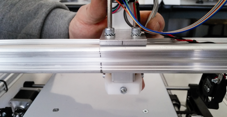
The following operation regards the removal of the existing extruder body, that has been fixed to a suppor that, in turn, is applied to the horizontal arm of the printer by means of two M5 screws. Before the removal, please leave a sign – by means of a pencil – on the printer arm, so to remember the original position of the nozzle (the sign must be placed in the center of the stirrup that supports the extruder), so to allow the correct positioning of the syringe’s needle and to allow to place the extruder in the correct position again, in the future.
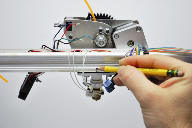
Now, please remove the extruder from the printer, by unscrewing the two fixing screws, as shown in figure;

please loosen the two fixing screws of the fan, so to move it on the right end of the arm, as needed in order to allow the assembly of the new extruder.
Please insert two M5 stover nuts in the upper hollow part of the printer arm and place the extruder for the chocolate on the arm, so that the syringe’s needle (that is to say, the center of the angle bracket) is aligned with the reference that we previously left by means of the pencil. Please fix the unit to the printer arm by means of two M5x16 cylindrical head screws, completed with a M5 toothed washer and of two 5×10 flat washers.
Choco extruder Wiring
Everything is now ready for carrying out the electric connections of the heating cartridge and of the extruder NTC, that you will create soon after having stripped, soldered and grouped – by means of small strips – the corresponding cables.
If you are using two heating cartridges (the cylindrical one and the “flat” one), they have to be connected in series among them and the element that we obtained must be connected to the clamps that are provided for the heating cartridge. Therefore, please twist the four wires of the stepper-motor among them, and connect them directly to the related clamps, by respecting the colours of the conductors: the motor’s Blue with the flat-cable’s Blue, the motor’s Red one with the flat-cable’s Green one, the motor’s Green one with the flat-cable’s Yellow one and the motor’s Black one with the flat-cable’s Orange one.
Please remember that, if you are using a Nema17 motor – whose cables have been shortened (for example, as in the one that has been recovered from the standard extruder of the 3Drag printer) – in order to reach the clamps it is needed to extend the related conductors by means of a part of the 4 way flat cable that is included in the 3D Choco modification kit: in this case we recommend to pay great attention, in order to avoid the inversion of the connection, since it would cause damages to the related driver. This being said, please group the motor’s conductors by means of strips and fix the wirings to the arm by means of strips in excess .

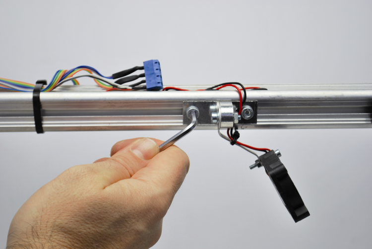
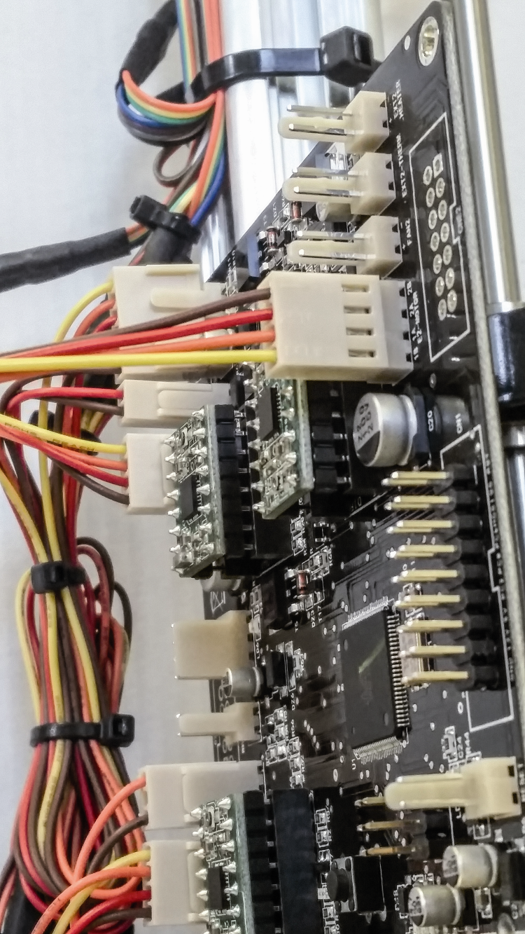
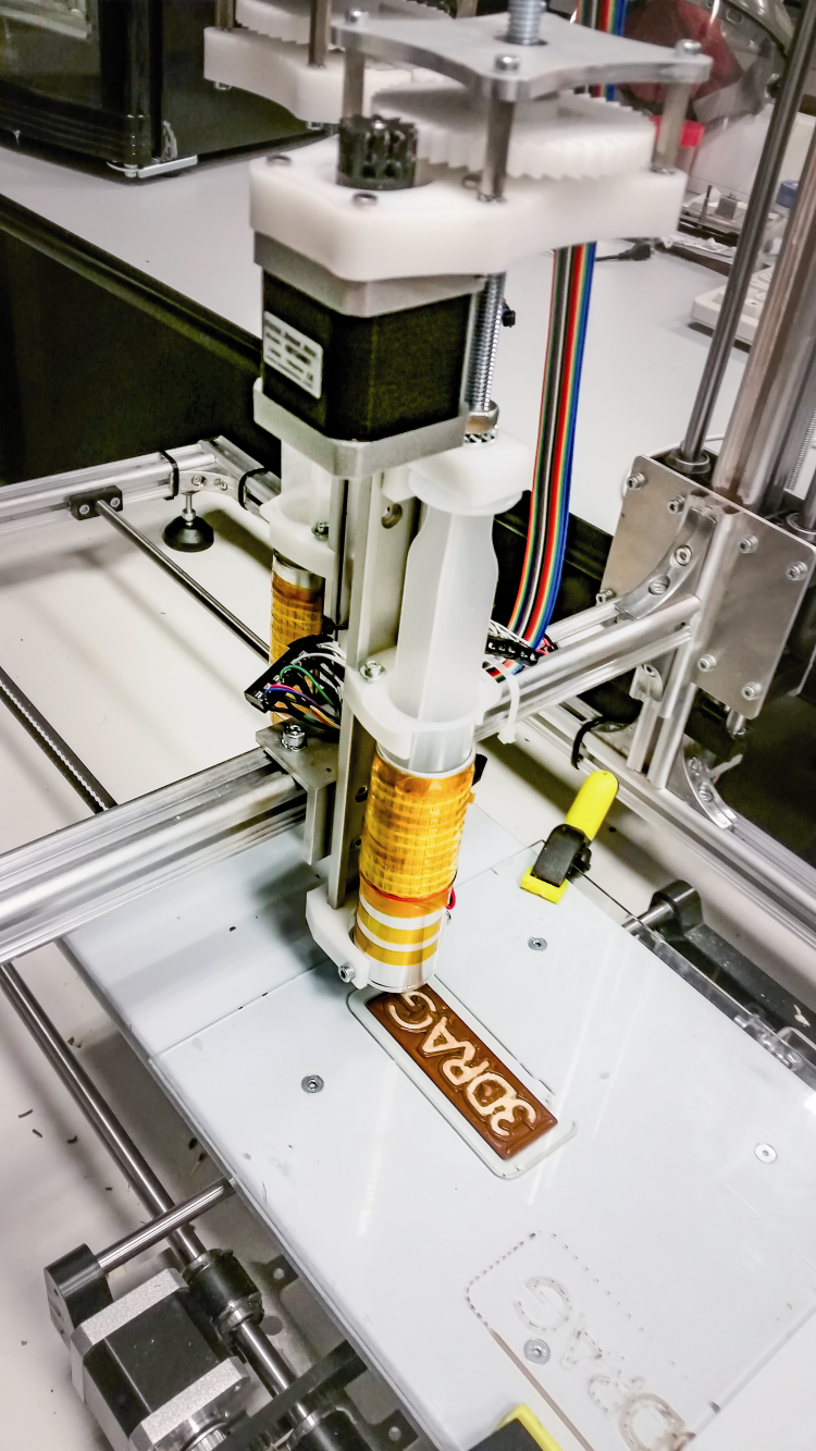
Once the wiring has been completed, the machine will appear as in figure

At this stage we have obtained our 3Drag Choco BIG and we are ready for the installation of the second extruder.
Installation and wiring for the second extruder
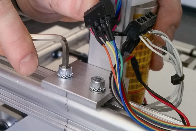
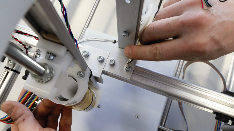
We now have to mount the second extruder for the chocolate, that will be placed on the side of the horizontal print head holder that is opposite to the one in which you mounted the first one: please cut the strip that blocks the flat cable in the part of the extruder for the chocolate, after that please loosen the screws of the extruder’s support and move the extruder towards the motor of the Z axis, and align the final part of the support with the sign that you previously left with the pencil.
Please insert two stover nuts in the runner and lay down the second extruder by slightly tightening the support’s screws.
Please make the second extruder slide, and bring it to contact with the first one, and finally tighten the related fixing screws.
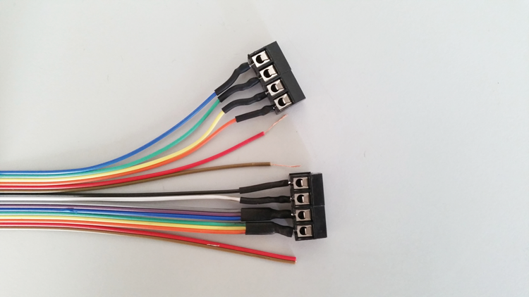
Please take a part of a flat cable that is 100 cm long and completely separate the two external wires having brown and red colours from the rest of the flat cable, and do this for all its length.
Please separate the wires’ groups for about 2 cm, as shown in figure.
Please strip the wires for 5 mm, then twist the wires of the same group; then strip the remaining wires for 5 mm: differently from the first ones, the latter ones do not have to be joined.
Please solder all the conductors, and pay particular attention to the twisted ones, since they require a greater quantity of tin.
Please repeat the same operation at the other end of the flat-cable, by soldering the clamps as:
Please fit and place the connectors as in figure and apply the second extruder’s flat-cable above the first one, after that please fix both by means of a strip.
Please repeat this operation with the other four strips, by first removing the existing ones.
Electric connections
Please connect the four motor’s cables to the four wires of the flat-cable, that have been previously soldered, by respecting the following framework:
– the Blue one with the Blue one of the extruder’s motor;
– the Green one with the Red one of the extruder’s motor;
– the Yellow one with the Green one of the extruder’s motor;
– the Orange one with the Black one of the extruder’s motor.
After that, please connect the small Grey, Purple, Blue and Green, Yellow, Orange cables of the flat cable, respectively to the red and brown cables of the heating cartridge; please connect the two small cables of the NTC to the White and Black conductors of the flat-cable.
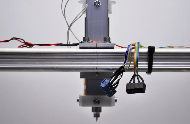
If you did everything correctly, you should obtain a result tat is similar to the one in figure.
If you didn’t consider a second fan, please remove the stripped part of the related wires and insulate it by means of the heat shrinking tube. Once this has been done, please lay down the connectors on the pipe support of the extruders, and secure them.
the new controller
Let’s move on, now, to the installation of the new board: please remove the power cable of the electric board and by means of an indelible marker pen, sign the female connectors of the motor and of the limit switch, as in figure: F will be the one related to the fan; the two connectors that are left without a name will be the ones related to the NTC probe (2 poles) and to the heating cartridge (4 poles) of the first extruder.

Now, please remove the control board by unscrewing the two support screws and later the female connectors as well.
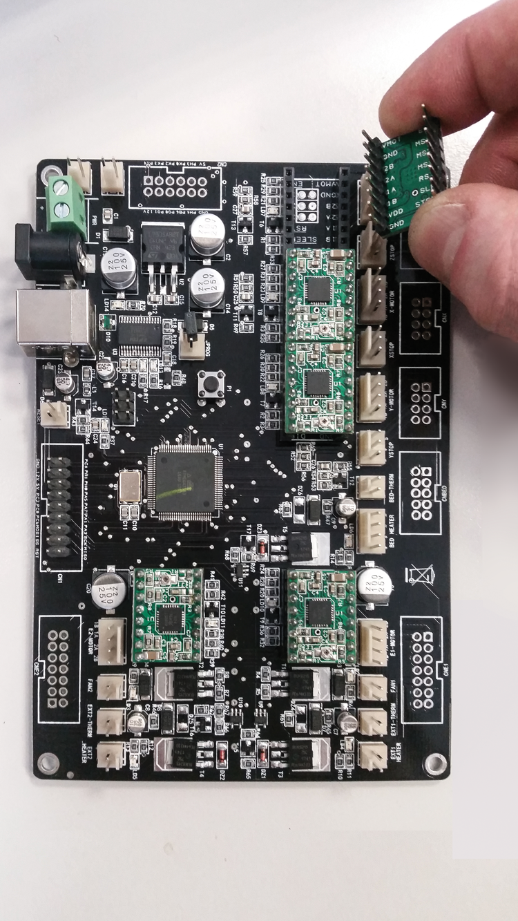
Please remove – by means of a ceramic screwdriver – the drivers of the motors of the old board and insert them in the corresponding connectors of the new one, and add the needed one and drive the motor of the second extruder for the chocolate.
Please pay great attention when installing the drivers in the right direction, as shown in figure, otherwise, once the board is powered you will damage it and them.
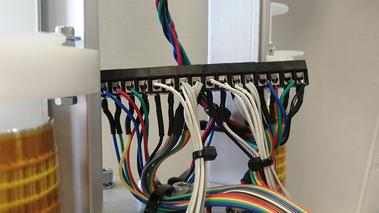
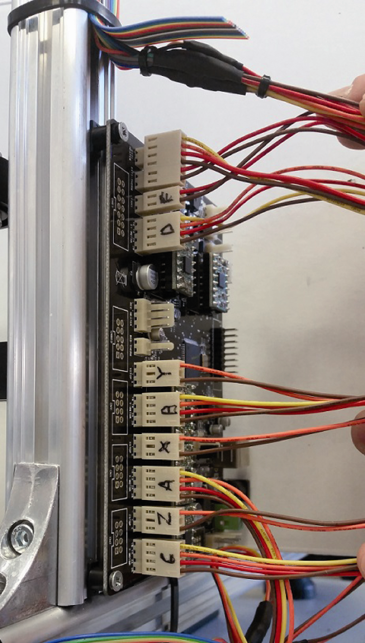
Once this has been done, please tighten the new board on the printer’s chassis by using the two screws that were previously removed; after that please remove all the strips that kept the connector wires in position and insert each connector in the corresponding one of the controller, accordingly to what is shown in figure, that is to say:
– 4-pole unnamed one -> EXT1 HEATER
– 2-pole unnamed one -> EXT1-THERM
– F -> FAN1 X ->XSTOP
– D -> E1-MOTOR A ->XMOTOR
– Y -> YSTOP Z ->ZSTOP
– B ->Y-MOTOR C ->Z-MOTOR
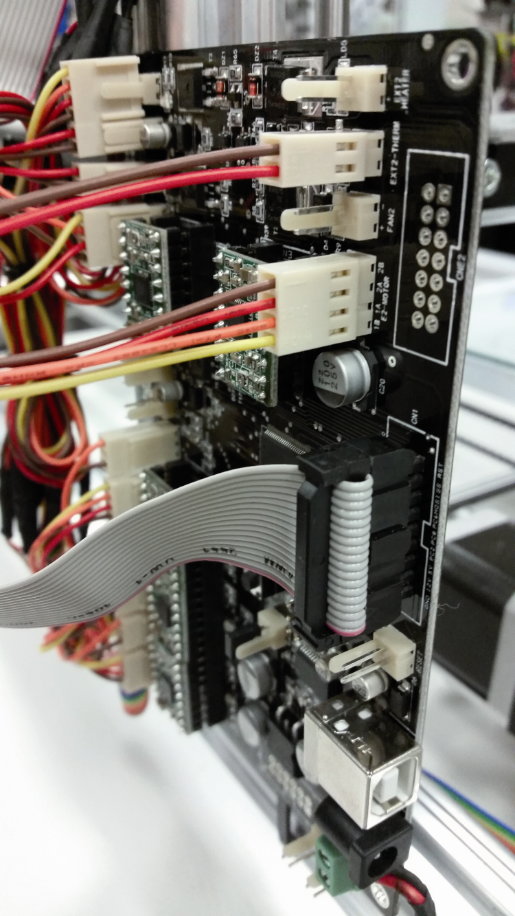
Please insert the 4-pole female connector in the board’s male connector that is signed as “E2-MOTOR”, as shown in the higher part of the figure . Please pick up a heat shrink tube having a smaller cross-section and cut four tubes having a length of 1.5 cm. Also, please cut 4 cm out of a heat shrink tube having a greater diameter. Please put the heat shrink tube you just cut (the one having a greater diameter) on the four small cables and after that please put the smaller heat shrink tube on each cable.
At this stage, please solder the four small cables of the female connector to the four small cables of the flat cable that were previously soldered, and respect the following framework:
– the Blue one of the flat-cable to the Yellow one of the female connector;
– the Green one of the flat-cable to the Orange one of the female connector;
– the Yellow one of the flat-cable to the Red one of the female connector;
– the Orange one of the flat-cable to the Brown one of the female connector.
Once this has been done, please place the smaller heat shrink tube on the solderings and make it shrink by means of a hair dryer or a heat gun. Please repeat the last operation with the heat shrink tube having a greater diameter, so to completely cover the junctions of the single cables.
Now, please pick up the 2-pole female connector and separate the Red and the Brown wires for about 2 cm, soldering them to the wires with the corresponding colours of the connector, only if you decided to mount the second fan, and – finally – insert the female connector in the “FAN2” position.
After that, please separate the White and Black wires for about 2 cm, then strip them for about 5 mm and solder them. Then pick up a heat shrink tube having a smaller diameter and cut two small tubes having a length of 1.5 cm.
Also, please cut 4 cm of a heat shrink tube having a medium diameter. Please apply the medium heat shrink tube on the two small cables and the smaller one as well, on each one of them; after that please solder the two small cables of the female connector to the two small cables of the flat-cable that have been previously soldered, and respect the following framework:
– the Black one of the flat-cable to the Red one of the female connector;
– the White one of the flat-cable to the Brown one of the female connector.
Please place the smaller heat shrink tube on the solderings and shrink it by means of a hair dryer or a heat gun, after that please slide the heat shrink having a greater diameter over the junctions and heat it, so to make it adhere to them. Now please separate the Grey, Purple, Blue and Green wires for about 2 cm, then strip all the small cables for 5 mm and twist together the wires of the two groups. Please solder them, then pick up the 2-pole female connector, that you will have to insert in the male connector of the board that is signed as ”HEATER2”. Please pick up the heat shrink tube having a medium diameter and cut two small tubes out of it, they will have a length of 1.5 cm. Please put the heat shrink tube thus obtained on the two small cables (the Red one and the Brown one) and a bigger part of heat shrink tube, having a length of 4 cm, on the whole, after that please solder the small cables to the wires of the flat-cable, by respecting the following framework:
– the Orange, Yellow, Green ones of the flat-cable to the Brown one of the female connector;
– the Blue, Purple, Grey ones of the flat-cable to the Red one of the female connector.
After that, please place the medium heat shrink tube on the soldering and shrink it by means of a hair dryer or a heat gun, then do the same with the bigger heat shrink tube. The wiring is thus completed; if you have any further doubt, please check the wiring diagram that has been published in the previous pages.
The firmware
In order to work with the chocolate, it is necessary to prevent that the extruder’s heater reaches temperatures that would make the chocolate lose its tempering, a condition that would make the chocolate – once it has solidified – lose its original texture. The heater must work at temperatures that are much lower than the ones considered by the Marlin firmware (that is installed in the 3Drag’s microcontroller); it was born for the purpose of controlling plastics fusion 3D printers, and includes a series of protections among which the one that does not make the extruder’s motor start under 170°C. Since we have to melt the chocolate at a temperature that is of about 33°C (this is the one for the dark chocolate) we have to modify the instruction at the #define EXTRUDE_MINTEMP 170 line, so that it becomes #define EXTRUDE_MINTEMP 10: this modification moves the protection threshold from 170 °C to 10 °C. Moreover, since we eliminated the heated plated and the corresponding NTC thermal sensor, the temperature of the plate will always be zero, which will prevent the printer to work; in order to solve the issue, you will have to modify the line 169, by setting min temp to zero: #define BED_MINTEMP 0. Another modification to be made to the firmware concerns the steps/mm of the extruder’s motor, and it is imposed by the different mechanics of the latter; the instruction to be modified is #define DEFAULT_AXIS_STEPS_PER_UNIT {64.25,64.25,2560,600} that allows a fluid extrusion of the chocolate. The last parameter indicates the motor’s rotation speed. In order to obtain a functional extrusion, it is necessary to reduce this parameter by ten times, therefore the correct instruction will become #define DEFAULT_AXIS_STEPS_PER_UNIT {64.25,64.25,2560,60}.
A further modification to the firmware concerns the PID for the temperature control, in order to prevent it from oscillating excessively: the #define DEFAULT_Kp 22.2 instruction must become #define DEFAULT_Kp 32.2. It is then needed to modify the line n° 402 “#define INVERT_E1_DIR true” in “#define INVERT_E1_DIR false”. Finally the line n° 424 must be modified as #define X_MAX_POS 400 so to increase the maximum size of the plate and therefore bring it to 40 cm.
You will be able to apply all these modifications to the original firmware, but you may also download the specific firmware here. The said firmware is the one for the 3Drag Big, that has been adapted for the dual extruder and with the abovementioned parameters that have already been updated.
From the Store
3DragChoco, the Chocolate extruder for 3D printer

I recently purchased hp ink 652, the best thing it is most reliable ink because it is compatible with most of the printers of HP and Canon.
good
thank you