
When the standard model is not enough, you can “stretch” the printer to print objects up to 400x200x200 millimeters. Here’s how to make the change.
To print great objects, you need a great printer -and our 3Drag is great- but if you want to print three-dimensional objects that are oversize, then you need a large printer. So we decided to work on a new 3Drag update, which differs from those already proposed (CNC milling machine, chocolate printer) because it is not only a change of printing head but rather a “lateral stretching” of the case to become big enough to allow printing up to 400x200x200 mm instead of the standard 200x200x200 mm objects size. In this way the 3Drag, from now on dubbed 3Drag Big, can print shoes prototypes, hulls for ship models, architectural scale models, aircraft parts like tails, wings or fuselage, and so on.
Without much fussing, we will explain how to turn your 3Drag into a 3Drag Big: to upgrade the standard model you have to replace the two side profiles of the base frame with longer ones (850 mm), the X-axis two Ø10 mm ground steel rods with two longer (797 mm), the X-axis belt with a 1.5 m long (available as spare part on openstore cod. BELT6T5 / 1500 / SP) and the original printing plate with a wider one, by 405×205 mm.
To complete the upgrade, you must also provide this material:
- one M5 square nut;
- a M5x12 screw;
- two M3x16 TC screws;
- 10 countersunk head M3x8 screws;
- one M5 toothed washer;
- 14xM3toothed washers;
- 12xM3 nuts;
- plastic ties 100 mm and 200 mm long
The aluminum square section profile used for the frame can be purchased from our store (cod. PROFALL275– available in 1 meter bars) while the Ø10 mm ground steel rods, the 2 mm thick aluminum plate and the two 405 mm long, 15x15x1,5 mm aluminum angle brackets (used to “enlarge” the printing plate), can be found in hardware stores or well supplied DIY centers.
Of course we must make again the motors and X&Z-axis limit switches wiring, having changed the corresponding elements position; for this purpose, we suggest to purchase the flat cable sold by Openstore cod. FC16C-3/SP, using only the needed wires.
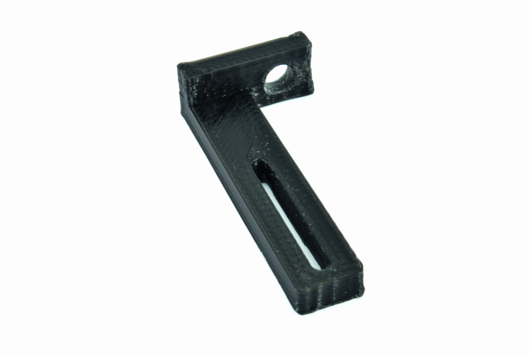
Before proceeding with the modifications, you need to print with the 3Drag the X-axis limit switch mounting bracket (shown in figure) whose “.stl files” can be downloaded here.
The first thing to do is cutting all the ties clipping the wiring coming from the control board and going to the X axis motor/limit switch, toward the X tray and to the Z axis motor/limit switch.
Then, remove the printing plate from the X tray (if you have installed the heated plate, its power supply and control cables must be disconnected and isolated by means of heat shrink pieces to prevent short circuits). Note that the heated plate is not available for the 3Drag Big, so you need to disable it; using Cura Engine as a slicer, just click Setup / Filament and set the value “5 ° C” for the “Plate temperature” and replace the NTC with a 22KOhm 1/4W resistance (otherwise the program will wait until the temperature set has been reached and will not start printing). If you prefer Slic3r, just set 0.0 temperature to turn off the plate.
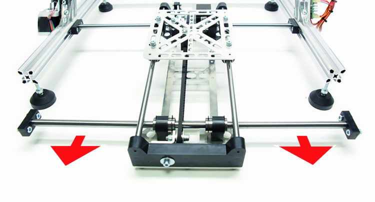
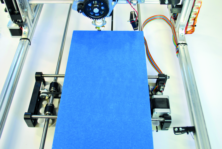
After that, let’s remove the X-axis motion system (toothed belt, motor with bracket, the pulley and its bracket that is fixed on the frame left side near the Z axis), as shown in figure.
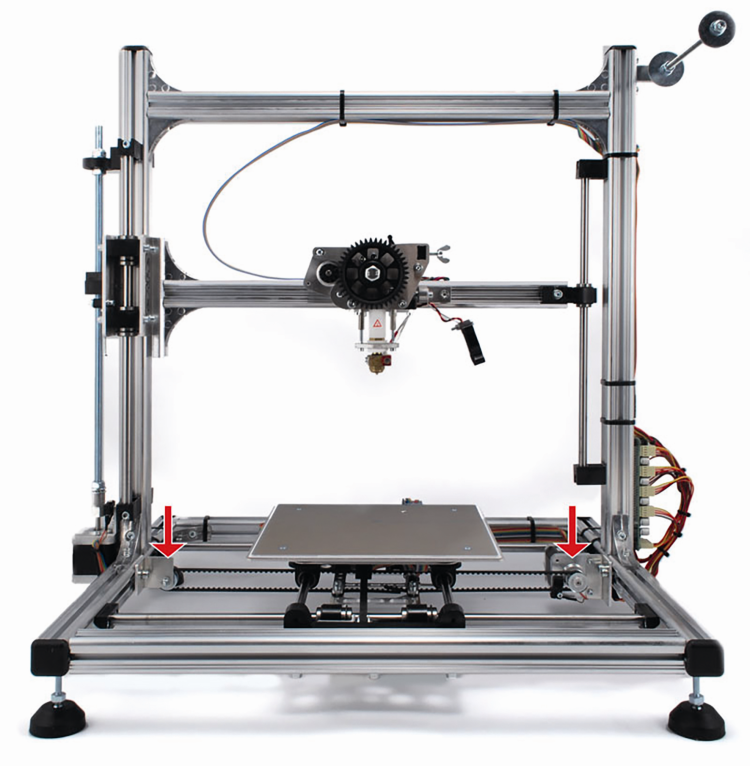
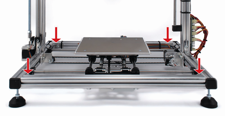
Now you can remove from the base frame the two 45 cm long aluminum profiles (front and rear) indicated by red arrows in figure (to do it, loosen the related angle brackets screws).
Keep apart these two profiles, since you’ll need them to complete the 3Drag Big frame.
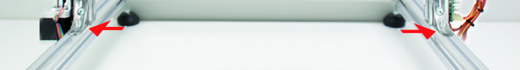
Now remove all the screws that lock the two X-axis Ø 10 mm ground rods to the frame; the screws are those shown in figure.
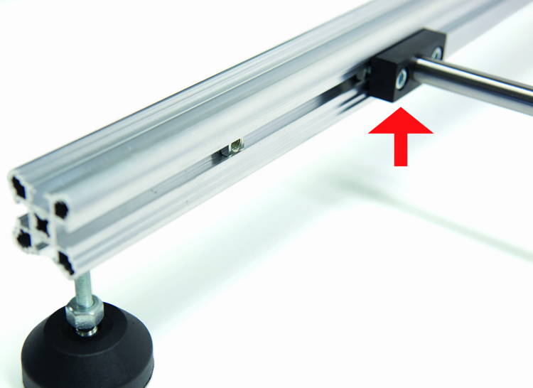
Done this, pull out the X-tray from the frame by sliding the related bars toward the printer front.
You can then extract the X-tray ground bars, then unscrew the four angle brackets at the base of the two struts and remove the two aluminum profiles put at the base frame side (the 416 mm long ones).
Mount the new 850 mm long profiles replacing those we have just removed; these are obtained by cutting properly the two 1 meter bars purchased from our store.
Temporarily position the new struts at the center of the two bars without tightening the related angle brackets screws (the correct position will be checked later).
Assemble on the 850 mm bar the 450 mm rear section (we disassembled it at the beginning of this guide) after inserting on the latter (the printer center facing end) five square nuts (used for X rods supports and pulley).
Fix temporarily to the bar by means of the nuts just entered the two X axis ground bars supports and, between these two (approximately in the center position), the X-axis pulley and its bracket.
Then tighten the angular profile screws (those assembling the 450 mm and the 850 mm sections together), and fix to the 850mm sections the four studs exactly as they were mounted on the original chassis.
Take the tray and place it at the center of the printer keeping its connection flat-cable facing the control board.
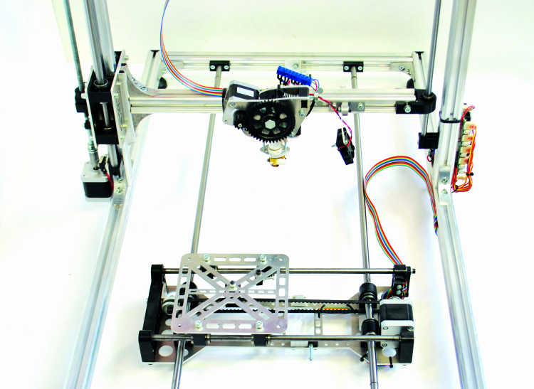
Now take the two 10 mm diameter and 797 mm long ground round bars and insert them first on the X-tray sleeves, then in the related supports previously fixed to the rear base profile (the 450 mm one); the situation will be that visible in figure.
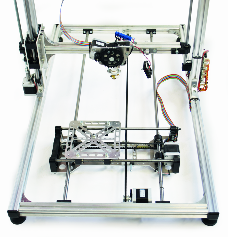
Place a M5 square nut in the 850 mm right profile appropriate cage (the profile is the one close to the control board, the cage is that facing the tray): this nut will be later used to secure the X-axis limit switch support. Now take the other 450 mm profile and do the same as before but this time you need to fix, between the two ground bar supports, the X-axis motor with the pulley facing left, as seen in figure; the pulley must be located approximately at the center of the bar and the bracket screws, for the moment, just hand tightened.
Mount together the 450mm section to the two 850mm side sections and lock them in place by tightening their angle brackets screws, then position the bars so that they are parallel and equidistant from the base side profiles. Slide the tray from one end to another to make sure it moves freely and tighten gradually and alternately all the screws on the support bar. If the tray movement is not smooth, repeat the alignment. Attach to the base, with a 200 mm tie, the tray flat cable. The result should be the one visible in figure.

Now it’s time to mount the X-axis motor so that its pulley is about 195 mm far from the controller hosting aluminum section. Place the other X-axis pulley so that its respective bracket is far about 200 mm from the same section bar.
Done so, you have to pin one end of the belt to the X-tray by using a clamp screw. Now stretch the belt and let it pass over the two X-axis pulleys, then insert the free end on the other clamp screw on the X-tray. Tighten loose the clamp screws just to avoid belt slipping and verify that the tray can move end-to-end smoothly. If it is ok, the two pulleys are aligned, otherwise correct the positioning of each element. Finally, secure all the related components permanently to the frame.
Aligned everything, loosen the latter clamp screw and stretch the belt to the right tension, then tighten the screws for the final fixing. Check again that the tray is free to slide on its guides from end to end.
The last operation on printer mechanics consists on positioning the two struts spaced 46 cm from the base front profile. When this is done, it must be double checked that the extruder nozzle is able to reach the two ends of the plate. If necessary, you have to correct the struts positions otherwise you can proceed tightening the angle bracket screws.
Wiring
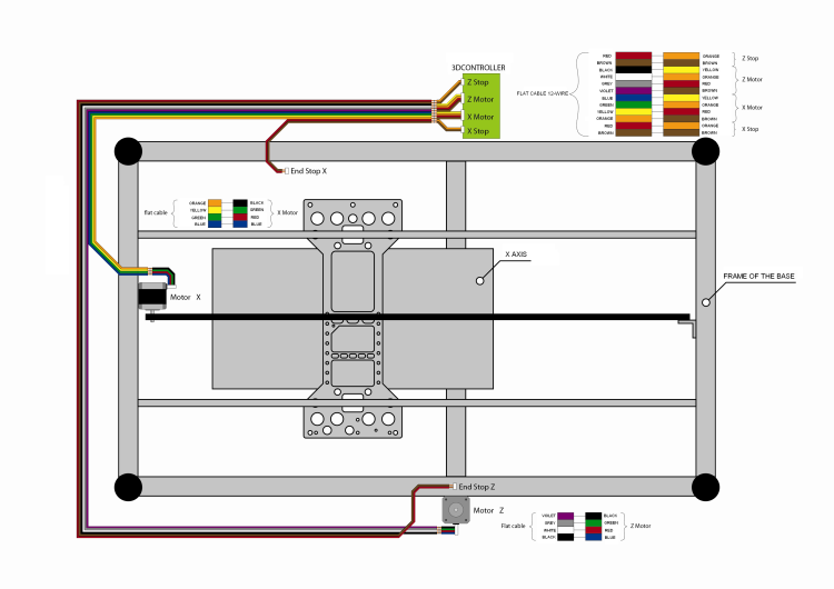
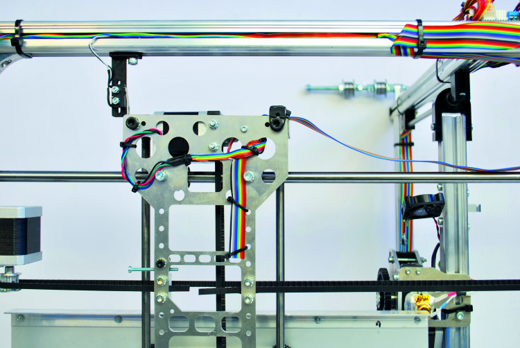
Once the mechanics has been completed, we must focus on rewiring the electrical and electronic parts; about this, which shows the electrical connection between the X/Z motors and their related limit switches to the 3Drag control board, done by using a 160cm 12-way flat cable suitably sectioned. One end of the flat cable must be connected to the printer control board using the board-to-wire cables recovered from the original 3Drag wiring, respecting the color association of each conductor as shown in the diagram.
Lay the printer on the Z-axis side, then distend under the base frame the flat cable leaving it near to the motor and to the Z axis limit switch (securing it with cable ties in the most suitable points) separating properly the conductors shown in the diagram in correspondence of the elements to be connected (motors, limit switches).
As a first step you have to connect the flat cable to the Z axis switch and just after its engine, following strictly the scheme, so as not to burn the motor driver.
Then connect the X-axis motor; Also in this case we recommend to fully observe the diagram in figure, to avoid damaging the driver.
Made connections, fix where necessary the flat cable to the frame, using the plastic ties.
Printer plate
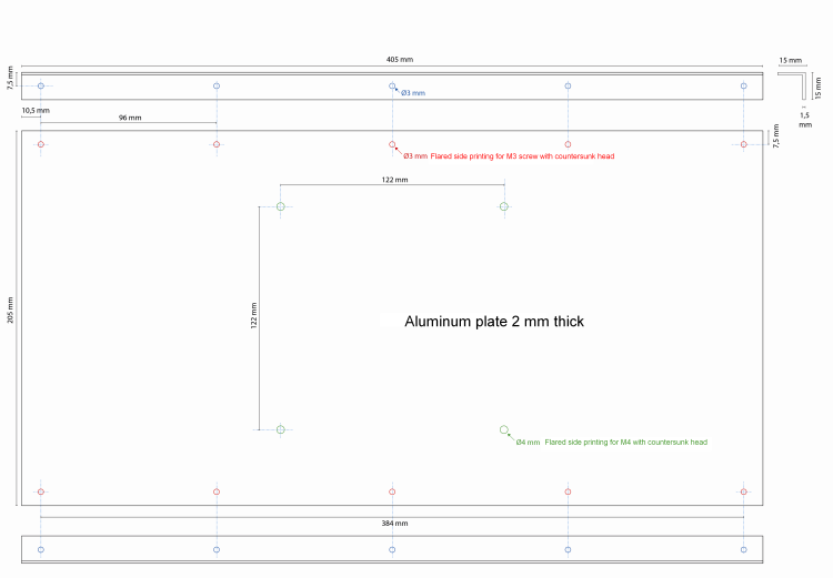
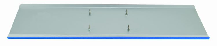
Now we focus on making the new printer plate (the X-axis limit switch will be addressed later): Take the 2 mm thick 205×405 mm aluminum plate and drill it as shown in figure.
All the holes done should be countersunk on one side (the plate “printing side”); the four central holes will host the same 4 M4x20 screws used on the original printing plate, while the ten holes drilled on the two longer sides will host 10xM3x8 countersunk head, fixing the angle brackets. Now take two 15x15x1,5 mm, 405 mm long aluminum brackets and draw on their side the center line. Then drill five Ø3mm holes spaced 96mm each other and starting from 10.5 mm from one end (these holes will be matching those done on the plate longer sides).
The angle bracket drilling guide with all the distances is reported in the figure.
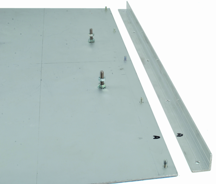
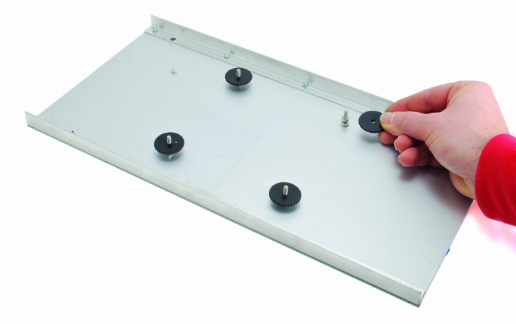
Screw tight all the M4x20 as in the original 3Drag plate. Insert the M3x8 screws, mount the angle brackets, insert on each screw a M3 toothed washer and a nut which you will use to fix the aluminum angle brackets. Now you can apply to the four central screws the gear knobs (which will serve to align the plate horizontally)

Now you can mount the plate on the printer tray. Note that to ensure the best printed object adhesion to the plate we suggest to apply the blue paper tape available at our store (cod. BLUTAPE3M) or two pcs of BuidTak, as shown in following figure. Now you can take care of the X axis limit switch, which must be removed from the X motor and mounted instead on the right side section profile (same side of the control board) using the bracket previously printed with 3Drag.
The support should be put about 14 cm from the front of the frame and secured with a M5x12 screw with toothed washer and the M5 nut previously inserted on the right side (the screw, for the moment, should be kept close). Now fix the microswitch to its support (by means of two M3x16 TC screws, each with four toothed washers and one M3 nut), after having positioned so that the metal tab touches the X-tray plastic support placed behind the Y motor.
Fix now the electrical connections, taking care to leave enough free cable (50 mm are more than enough) in order to have the possibility, during the calibration phase, to move a few centimeters the limit switch.

Move the plate toward the X motor so that the nozzle is aligned with the end of the plate itself and then fix the limit switch so that it is triggered at this very point. Finally tighten with an Allen wrench the M5 screw; this adjustment is not critical but determines the X-axis “HOME” position. Now you can finish the job by fixing with a 100mm plastic cable tie the wiring.
Using the 3Drag Big
To fully utilize the printing area you need to change the printer settings (in Repetier-Host click on Configuration/Printer settings/printing plate options) by entering the new plate size (the X axis).
The printing time of larger items can be reduced by replacing the standard 0.5 mm nozzle with a 0.8 mm (available from our store cod. NOZZLE08)
3Drag BIG allows the mounting of a printing plate having maximum dimensions of 550×205 mm, like the one visible in figure, obtained from a 2 mm thick aluminum “sheet” folded at 90 ° on the longer sides.
It is imperative to keep in mind that the larger plate dimensions allow the printing of bigger objects but also that this increases the whole printing system oscillations, reducing thus the definition and quality of the final output.
From openstore
Expansion set for printer 3Drag
Aluminium profile 27,5mm x 27,5mm – 1m
Toothed rubber belt – 1.5 meters

[…] We won’t publish the circuit diagrams and the assembly instructions of the 3Drag printer again, and we refer you to the corresponding articles; in these pages we will describe the modifications that are needed in order to transform the 3Drag BIG in a 3Drag BIG DualChoco. Those who already have a 3Drag will be able to find the instructions for its transformation in a 3Drag Big (that will be the starting point) at the following web page: 3DRAG BIG […]