

Among the user interfaces available on the market, there is the one recently developed by Microchip and based on a new technology for gesture recognition, suitable for the creation of innovative man-machine interfaces. This function is created by means of a dedicated integrated circuit, named MGC3130, capable of detecting a basic series of movements, and that can be updated in time to integrate or improve the performances and to possibly add new motion detection algorithms.
At this point you might be wondering what is this technology about: basically it takes advantage of the interaction between the hands and a conveniently generated electric field, in this way when the hands interfere with the field lines a variation in the distribution of the electric field is detected; such a variation is intercepted by the integrated Microchip that manages to recognize the movement made by the user (this new technology takes the name of GestIC Technology Colibri Gesture).
Operating Principle
To generate an electric field in the three-dimensional space an electrically charged electrode (TX) is used; if the electric charge is generated by a DC voltage a constant electric field is obtained, while if the charge is generated by an alternating current voltage an electric field that similarly varies in time is obtained.
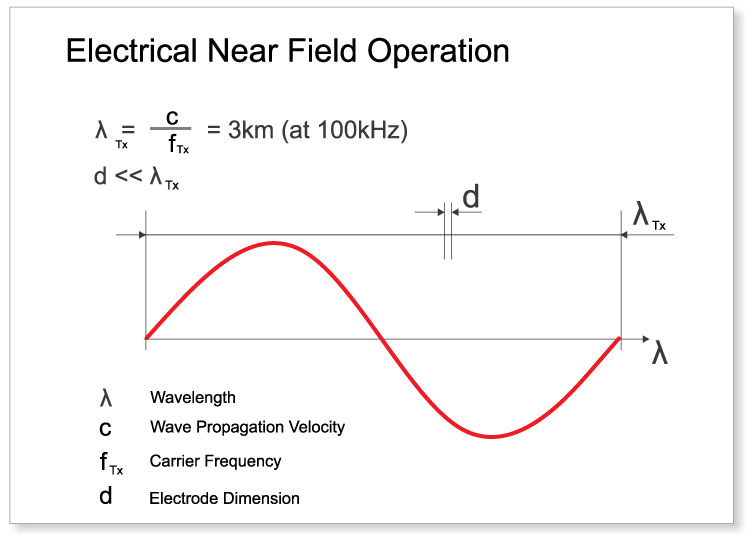
The Microchip technology uses a f frequency that is equal to 100 kHz and that originates a wavelength equal to 3 km. With an electrode geometry much smaller than the wavelength (usually 20×20 cm), the field’s magnetic component is negligible if driving, in the proximity of the electrode, an almost static field, and this can be exploited to detect possible conductive items (such as the human body, with hands, fingers, etc.), that perturbate the generated electric field. That said, it is easy to understand that if a person puts his hand within the sensitive area, he creates a perturbation of the electric field’s distribution by inducing a distortion, in fact the field lines intercepted by the hand are deviated towards ground by taking advantage of the conductivity of the same human body.
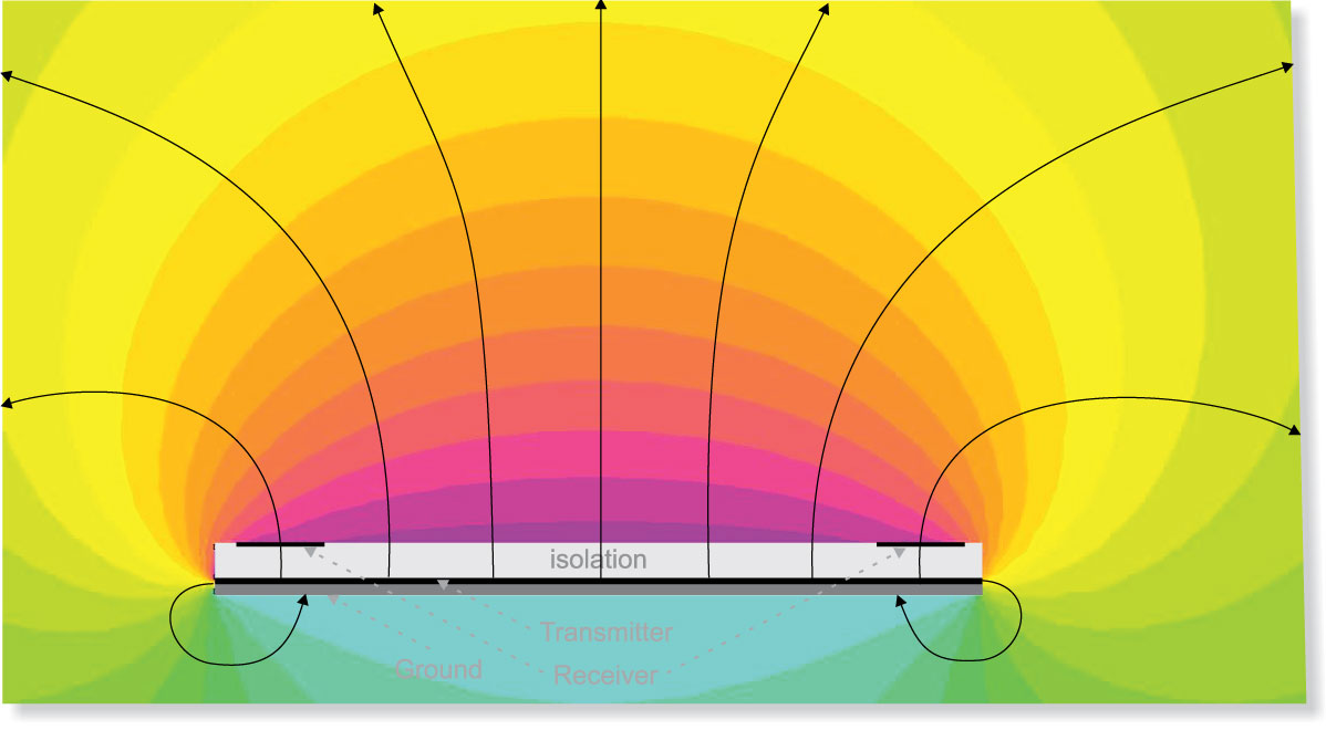
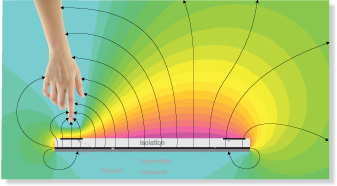
Figures point out what has just been said: the first one shows the electric field at rest while the second one points out how the electric field is perturbated by the hand’s action. In second sigure the interaction between the hand and the electric field is pointed out, along with the equipotential lines. The MGC3130 integrated circuit, by means of the receiving electrode (RX), “sees” a signal variation due to a potential energy decrease, this variation is processed by the MGC3130 integrated circuit and translated in a gesture. Going more into detail, a series of receiving electrodes (RX) must be connected to the MGC3130 integrated circuit, in addition to a transmission electrode (TX). Usually, the receiving electrodes are four and they identify the four cardinal directions (North, South, East and West) moreover there is a possible fifth electrode placed at the center of the cardinal points. The four electrodes (North, South, East and West) are used for the gesture recognition and to trace the position while the fifth central electrode is used to detect the touch on the part of the user and to improve the measuring of the hand in respect to the electrodes.
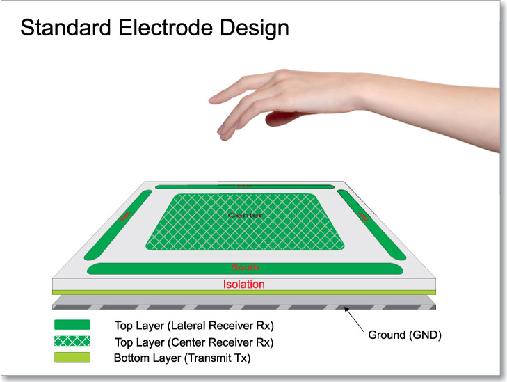

Figure shows how a recognition system is typically created: in this case we have the four receiving electrodes in the four cardinal points, in addition to the central one (Top Layer) and a transmission electrode placed on the Bottom Layer. The PCB is of the double sided kind, but in some cases it could be useful to create a multilayer PCB where the receiving electrodes are always on the Top Layer, while the transmission electrode is found in the second internal layer. The Bottom Layer is used to create a generous ground plane. The electrodes can be created by taking advantage of different supports, depending on the applications, for example:
- traditional rigid PCB;
- flexible PCB;
- conductive sheets.
It can be created even as coating on a glassy surface, by using the ITO-Coating technology.
The electrodes, theory of operation and design
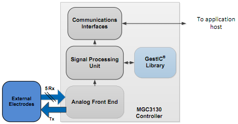
The MGC3130 integrated circuit can manage one and up to five receiving electrodes (RX), and only one transmissione electrode (TX). Figure summarizes the functional blocks found on the MGC3130 integrated circuit and that are noticeable in a “front-end” (to which to connect the transmission and receiving electrodes), a processing unit that receives data from the front-end and assisted by a GestIC library and finally, a communication interface for the data interconnection between the MGC3130 and a PIC or another microcontroller.
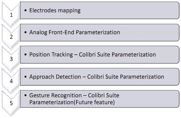
The design of a Gestic system requires a careful evaluation of the usage we want to make, of the kind of functions to be supported, and of how we mean to integrate the transmission and receiving electrodes on our application. Therefore the design of a Gestic system can be summarized by a flowchart, as shown:
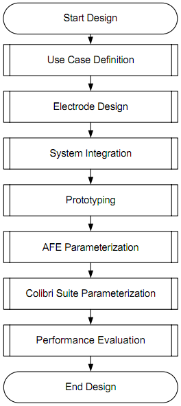
As a first thing one must define the use cases, that is to say: where and how the product we want to create will be used. We then have to decide how the transmission and receiving electrodes have to be created. In other words, their size, their positioning on the PCB and on the ground plane.
In the next step, we have to study how the MGC3130 integrated circuit can be integrated in a project, that is to say, his position in respect to the electrodes, the tracks’ layout and so on.
The PCB prototyping follows and, after that, it is the time of the parametrization of the MGC3130 integrated circuit’s front-end, in turn followed by that of the transmission and receiving signals. Finally, we will have to execute the parametrization of the Colibrì suite and execute a series of measures to verify its functionality.
As hinted before, the first step to execute when designing a system that takes advantage of the Gestic technology is to study the use cases of it. This is a very important phase since it affects the size and the sensors’ shape factor.
As a first thing it must be decided if the application is thought to be managed with the hand or with the fingers. In the case the application has to be managed with the hand, the electrodes must be engineered so that they might offer a work surface bigger than five inches. In the case you think to use the fingers, the work surface must be smaller than 5 inches.
In addition to this, it is important to know how the posture of hands or fingers will be, these pieces of information are important parameters for the creation of the electrodes and the parametrization of the Colibrì suite. The hand can be used in parallel to the sensitive area, perpendicularly or with a certain angle. The sensitive area is always the one defined within the four cardinal receiving electrodes, the geometric shape of the sensitive area is a key factor and may depend even on the geometry of the final product. Moreover, we have to keep into account of the sensitive area that is obtained, that in many cases may not be fully usable to track movements.
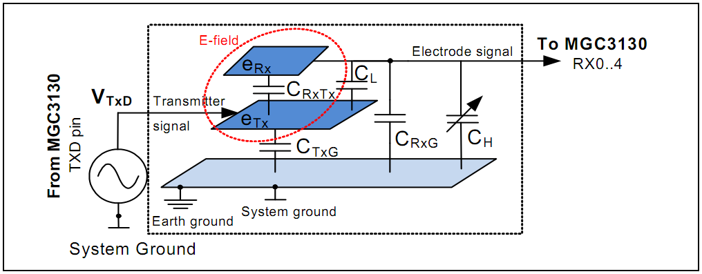
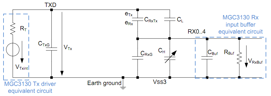
The simplified corresponding circuit of the Gestic system’s electrodes may be summarized by figures. This model gives us the possibility to evaluate the system’s features and to point out the dependencies between the electrodes, the MGC3130 integrated circuit and the hand. In particular, the electrodes capacities that are coupled to the input/output sections of the MGC3130 integrated circuit. Here, VTX is the output signal found on the TXD pin of the MCG3130 integrated circuit and CTXG is the capacity of the pin itself.
The parametrization of the corresponding circuit is based on the CRXTX, CRXG, CL e CH capacities. The first one is the capacity between the transmission electrode and the receiving one, the second one is the capacity between the receiving electrode and the ground, the third one is the capacitive coupling between the TXD transmission pin and the RX receiving line, finally the capacity between the hand and the RX receiving electrode. As you will notice, the CH value is represented as a variable capacitor, since such a capacity depends on the hand and on his position in respect to the receiving electrode. The eTX and eRX wordings identify the transmission and receiving electrodes.
The RX receiving electrode measures the electric field’s potential and if a conductive object, such as a hand, interacts with the electric field the CH capacity of the receiving electrode will change of a few femtofarads and such a variation will be intercepted by the MGC3130 integrated circuit.

The RXDIFF[7:0] register contains a constant that is needed to obtain the maximum dynamics. For each receiving electrode there is the relative RXDIFF[7:0] register. During the parametrization of this register we must ensure that the electric field generated by the TX electrode is not disturbed by foreign objects. The register’s parametrization consists in obtaining a signal that is approximately equal to VDDA/2 at the sampling point that is equal to about 32768 points of the ADC 16Bit converter (one for each receiving electrode).

To reach a high sensitivity, the receiving electrodes’ area must be of the same order of magnitude of the hand or the fingers, depending on the cases. Moreover the electrodes (excluding the central one) must have an elongated shape so to increase the coupling between the receiving electrode and the hand. The size of the receiving electrodes determines the sensitive area (central electrode), such sensors must always stay on the sides of such an area to obtain the maximum resolution for the x, y and z coordinates.
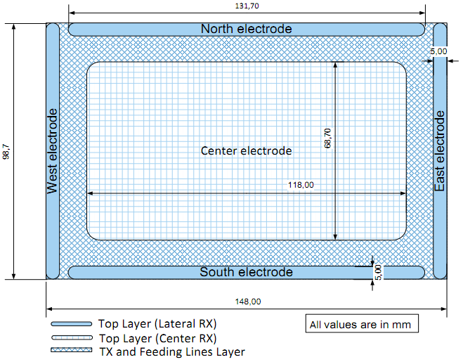
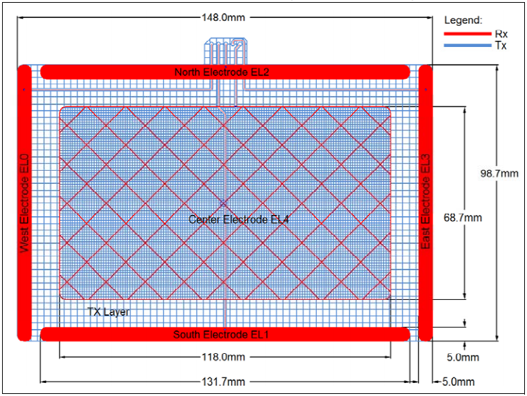
What has just been said can be summarized by figure, where a design example of a 7” Gestic system is shown. The width of the RX electrode (we refer here to the perimeter electrodes alone) depends on how much sensitivity we expect to have when the hand is really close to the electrode; the more the width increases, the more the sensitivity increases. Vice versa, the width of the RX electrode loses importance when the hand gets farther from the electrodes.

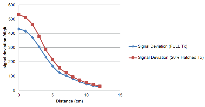
Figure shows a graphic where to see the signal deviation (measured in digits) in respect to the distance of the hand compared to the receiving electrode. As it can be observed, the more the distance increases, the more the deviation decreases. The four signals shown in the graphic differ for the electrode’s width.
It is a different matter for the central electrode that, in order to have the same sensitivity of the perimeter electrodes, has to be of the grid kind, in other words it must not be built of full copper. The grid design reduces the electrode’s effective area and the coupling towards the TX electrode. An acceptable coverage value for the grid is between 5% and 20%.

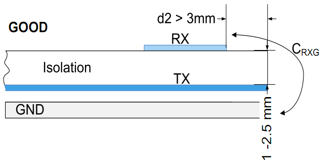
All that is left to do is to define how to relate the RX electrodes in respect to the ground plane. To do that, we have to keep the CRXG capacity into account; it has to be reduced as much as possible, thus we have to increase as much as possible the distance between the TX and the RX electrodes, at a PCB level, and to increase the distance in respect to the receiving electrodes’ ground.
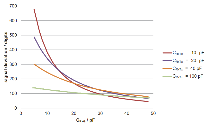
The more the capacity between the electrodes increases, the more the CRXG capacity will be able to generate a signal deviation on the RX electrodes, in other words the reading made by the sensor will be less prone to errors due to the CRXG capacity.
Let’s talk now of the TX electrode, that deals with the generation of the electric field needed. His shape and size have to be extended to the point to cover the whole receiving area, as formed by the RX electrodes. The TX electrode has to respect two rules:
- Low coupling between the RX and the TX electrodes
- Low coupling towards ground.
To reach such objectives, one must avoid to design an electrode that is full, but we must choose a grid-shaped electrode; by doing in this way we will reduce the CRXTX capacity and the CTXG capacity. The electrode’s grid effect, to obtain a good results, must be around 20% and 50%.
Another important factor, as hinted before, is the distance between the RX receiving electrodes and the TX transmission electrode. By increasing the distance between them, the system sensitivity is increased, since the CRXTX capacity is decreased.
Parametrization
The parametrization flow considers a series of steps to follow, in order to obtain the best performances from the system. Figure shows the steps to follow, starting from the receiving electrodes parametrization; they are named depending on their cardinal direction: North, South, East, West. During the parametrization, each electrode is coupled with his corresponding RX input. The relation between the electrode and the integrated circuit’s input can be updated at any time by the user, by using the dedicated configuration messages.

The second step consists in the parametrization of the analog Front-End or better still of the RxDIFF register, there is one for each analog input, so that it may have the maximum dynamics. The parametrization consists in obtaining a flat signal at the sampling point with a value of VDDA/2 approximately corresponding to 32768 points. During this kind of parametrization, the electric field must not be perturbated.
Once the first two steps have been completed, we have to go on with the parametrization of the Colibrì suite, that consists of Position Tracking, Approach Detection and Gesture Recognition. The application decides which property has to be used and thus parametrized; the properties of the Colibrì suite are of the inclusive kind and the user may choose one or a combination of them.
The Position Tracking must be adjusted to the size of the electrodes and to their features; such parametrization is intended to regularise the size of the sensitive area and to equalise the electrodes’ signal. Approach Detection determines which electrode will be used to wake up the system from the sleep condition.
At this stage, all that is left for us to do is to put theory into practice, thus we will describe the 80x80mm electrode’s parametrization step by step, by using the Aurea 1.2.4 suite (for our three electrodes we will supply the parametrization files to load into the MGC310 integrated circuit anyway; however if the user wanted to, be it for purposes of pure study or for need, he would be able to parametrize the integrated circuit and the corresponding electrodes again in order to better align them for his application, by starting from our files).
The Aurea software presents itself as an application divided in three different TABs:
- Colibri Suite;
- Signal:
- Setup.
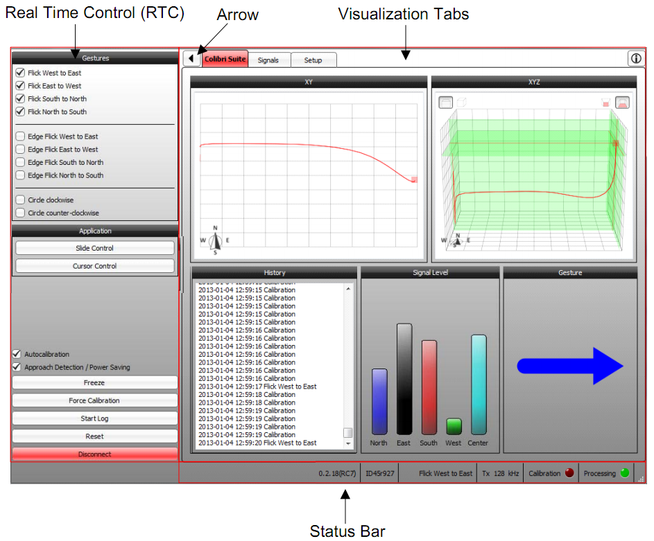
In the “Colibri Suite” TAB, the application keeps on querying the MGC3130 integrated circuit, showing the possible gestures that are recognized. Everything is displayed by means of a series of graphics, one of which is three-dimensional. Down and on the right the recognized gestures are displayed, while the checkboxes (up and on the left) are used to set up which gestures the integrated circuit must recognize.

The “Signal” TAB shows the development in time of the signals on the electrodes.
Finally, the “Setup” TAB comes up with three separate options. Of these, the only one of interest for us is “Parametrization”. By clicking on the “Parametrization” entry, we access the configuration window, in which the first step to make is the electrodes’ mapping.
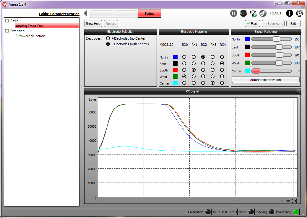
In our case, by respecting the electric plan, we assigned the West electrode to the RX0 input, the South electrode to the RX1 input, the North electrode to the RX2 input, the central electrode to the RX3 input and finally, the East electrode to the RX4 input (If the application does not consider the central electrode, the “4 Electrodes” option must be selected). Once the electrode mapping is ended, click on “Autoparametrization” for the configuration of the RxDIFF registers, one for each input, in order to obtain the maximum dynamics, as previously described (You will see the generation in the graphic below, step by step). Once the electrodes’ mapping has been completed, click on the “Extended → Firmware Selection” entry and in the window that will appear please select the 1.2.4 version as “Firmware” (that’s the default one) while at the “Parameters” entry we have to leave what has been indicated if it is a new parametrization, or to load a premade configuration file. If one wanted to, it would be possible to assign an “ID” with a maximum length of 8 characters (which is the advised number).
There is nothing left to do but to click on the “Start Parametrization” entry.

Figure shows the first configuration page, in which it is possible to configure, in sequence, the transmission frequencies of the TX electrode, the data we want to make available during the status reading and, finally, the active gestures.
In the next step the “Position Tracking” entry is expanded and we proceed with the “Electrode Dimensions” entry. In this page the distance between the North and the South electrodes is set up, as well as the distance between the West and the East electrodes. In our case, for a 80x80mm electrode the two distances are respectively 70mm and 70mm, and in practice we defined the work area.

The “Electrode Weighing” entry needs, in order to be completed, the building of a parallelepiped whose whole surface is covered by copper, which is needed to simulate the hand. The parallelepiped’s base must be 40x40mm with a height of 70mm. The thickness of the copper sheet must be of 0,35um. To help ourselves with the creation we may start by building a cardboard parallelepiped, by adding stiffness to the structure, and then covering it with a copper sheet. To help the parametrization, and to keep at the right distance the copper parallelepiped from the sensitive area, we advice to create a series of parallelepipeds of cardboard alone. All of them must have a 40x40mm base but different heights, that is to say: 10mm, 30mm, 50mm and 80mm. Fig. 28 shows the configuration window for the “Electrode Weighing” parameter, as it can be noticed the process must be repeated for all the five electrodes. The distance that the copper parallelepiped must have from each electrode is equal to 30 mm for this measure; moreover we have to remember that the parallelepiped must always be connected to a GND, as the figure points out. The parametrization always starts from the North electrode, to be completed with the central electrode in the end. Let’s thus click on “Start Measurement”, the system will start to execute a series of samplings that will be entered in the table, at this stage the system will propose to take away the parallelepiped from the electrode within 10 seconds, and will repeat the same measurement and verify then that the delta entered in the table, at the end of the calculations, is positive. In the case in which any parameter has a negative value, the measurement must be repeated.
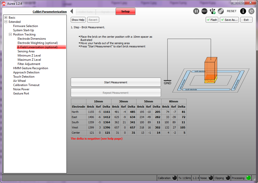
The next “E-Field linearization” parametrization, uses the same idea we just explained but it concentrates on the central electrode alone, with the parallelepiped kept at different distances (10mm, 30mm, 50mm and 80mm).

At the next step we have to parametrize the “Sensing Area”. This parametrization tries to define the optimal work area, that is to say, the area subtended by the four electrodes. At this stage, please draw a square with the index finger of your hand, by sliding on the four cardinal electrodes and keeping yourself a few millimeters distant. You will see a sort of square being drawn in the plot area. Once this square has been obtain you will have to act on the Xmin, Xmax, Ymin and Ymax cursors, so to center the work area within the square drawn in the plot area.
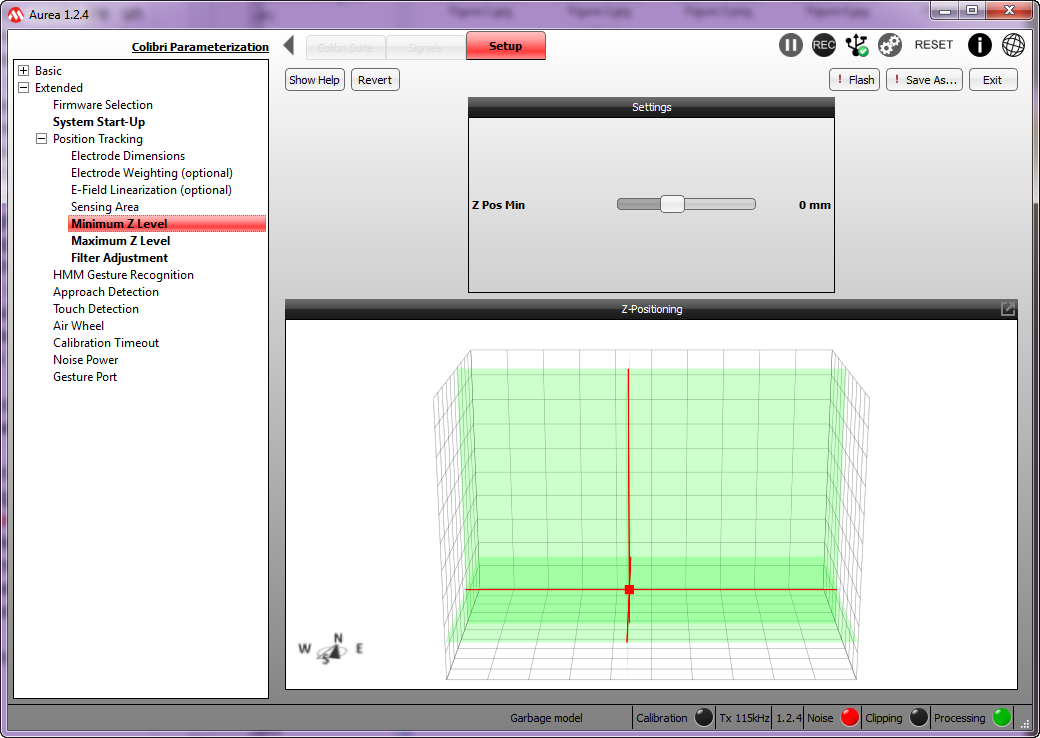
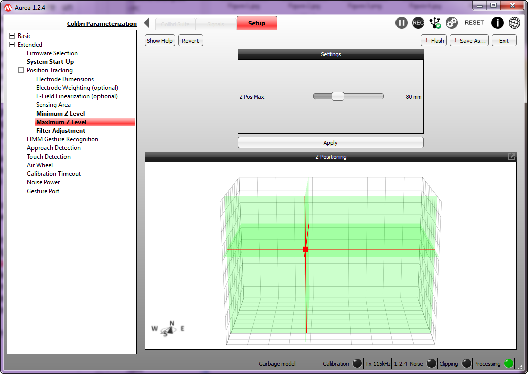
The two next steps are needed to set up the “Minimum Z Level” and the “Maximum Z Level”. In practice we have to find the maximum and the minimum values for the Z coordinate.

We then go on to the “Filter Adjustment” stage, so to reduce the jitter and to define the tracking speed of the hand movements. In most cases it is possible to leave the default parameters, that is to say Jitter at 80% and the tracking speed at 30%.
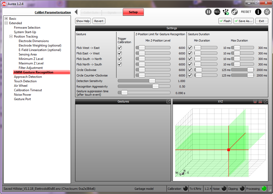
The next step is an important one and defines the parametrization for the “HMM Gesture Recognition”, with HMM indicating the Hidden Markov Models. Let’s start by defining the “Detection Sensitivity” that identifies the sensitivity in recognizing the gesture. If we set up a low value we are more conservative and the gesture must be performed near the electrodes, in order to be detected; if on the other hand we set up a high value the gesture is recognized even if performed far from the electrodes, in this last case we are however more prone to disturbances. Another important parameter is the “Recognition Aggressiveness”, that has to be kept at a value not being too high, to avoid false positives. Finally, “Gesture suppression time” that identifies how much time has to pass from one gesture recognized to the next one. Therefore, all the gestures detected before this time has passed will be trashed. The parameters under the “Z-Position Limit for Gesture Recognition” entry indicate over which minimal Z-axis level the indicated gestures will be recognized. This could be useful if above the receiving electrodes a glass or else is placed. Finally, the parameters under the “Gesture Duration” entry, that identify two possible values: the minimal value identifies how much a gesture has to last in order to be identified and considered as valid, while the maximum value identifies the time above which the gesture is refused. The Clock Wise and Counter Clock Wise gestures have a maximum duration that is always greater than the normal gestures, as it appears obvious.

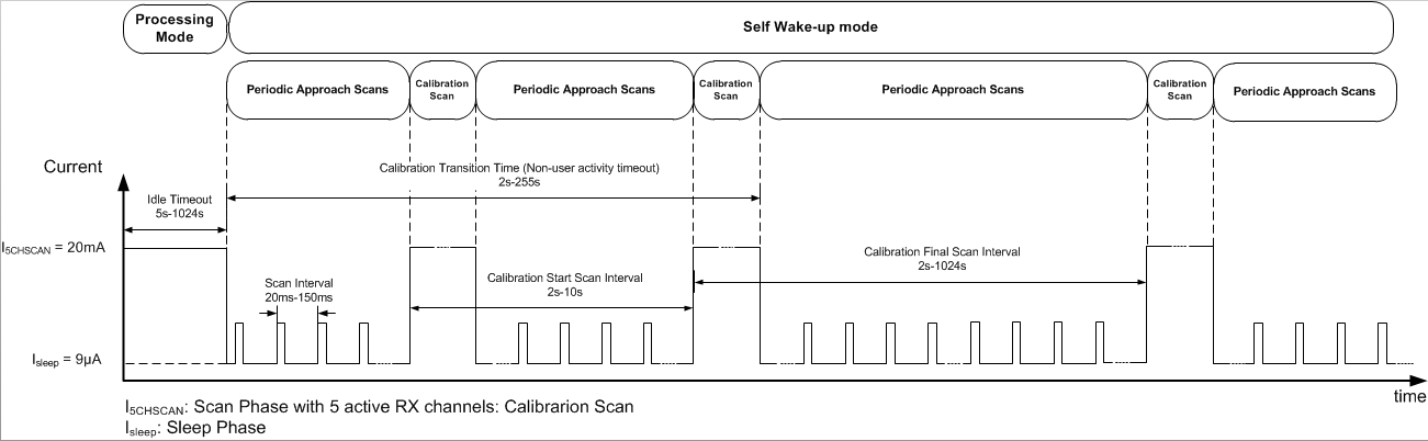
We may now move on to the “Approach Detection” entry, here one or more electrodes can be configured, in order to “wake up” the integrated circuit from the Idle state. As a first step we have to decide if to use one or more electrodes and which ones, in our example we will only use the central electrode. The “Sensitivity” entry identifies the sensitivity to give to the electrode, the “Scan Interval” entry identifies the reaction time of the system; if the value is low the response time is quick but the power consumption in Idle state is greater; in the opposite case less power is drawn but the response time is greater. The “Idle TimeOut” interval determines how much time is needed by the system to enter the Idle mode from the last recognized gesture.
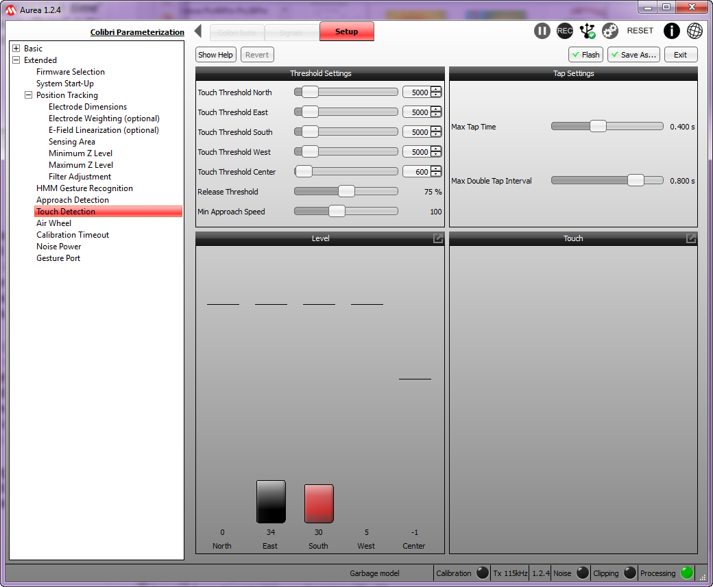
The next calibration page, “Touch Detection” is needed to set up the electrodes’ thresholds under which the touch is not recognized. As usual, we have to find a middle way between sensitivity, noise immunity, and so on. The “Tap Settings” section is needed to set up the recognition time of tap and double tap.
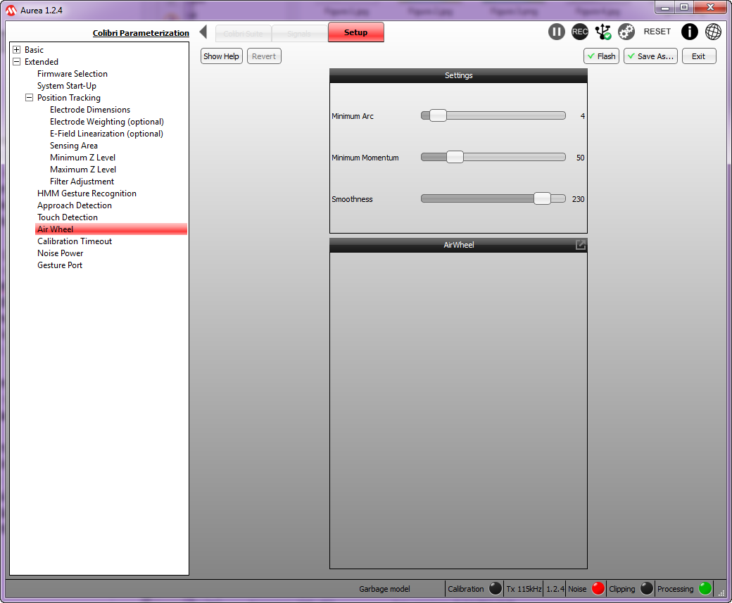
The “Air Wheel” page is needed to parametrize the circular movement recognition, thus we define the “Minimum Arc”, that is to say the minimum arc by which the system recognizes the circular gesture, the “Minimum Momentum” value determines how much we have to get close to the electrodes for the gesture to be recognized; low values assure a stronger immunity to noise and false positives. Finally, “Smoothness” determines how fast the counter is increased or decreased. With low values the counter is slowly increased, vice versa it is increased quickly.
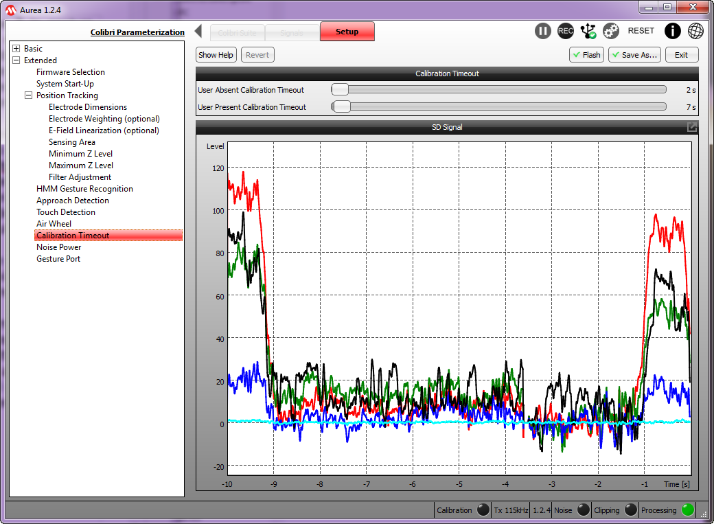
The “Calibration TimeOut” page allows to set up two calibration timeouts: the first one, “Absent User Calibration TimeOut” defines the timeout that, once expired, starts the execution of a calibration, provided that in addition to the expired timeout there are no objects moving in the sensitive area and that the signal deviation, measured on the electrodes, is less than 30 digits. The second one, “Active User Calibration TimeOut” defines the timeout that, once expired, starts a calibration even if there are no objects in the sensitive area.

The “Noise Power” page allows to set up three threshold levels in respect to the noise variance. The threshold levels concern the Touch recognition on the electrodes, the position tracking and the gesture recognition. If the measured noise exceeds the thresholds, then the respective function will be disabled until the noise does not decrease under the threshold value. If the thresholds are set to zero, the respective filter functions are disabled.

The last page, “Gesture Port”, allows to assign a gesture to an output pin of the integrated circuit. This has not been used in our specific case, but it may surely prove useful in other applications.
Conclusions
With this first installment, we have offered an in-depth overview of the Gesture’s world, on the basis of Microchip’s Colibrì’s suite.
We will then supply three possible electrode boards with different form factors, and related parametrizations, of course those who are interested will be able to parametrize again the MGC3130 integrated circuit, according to their specifications and requirements, by starting from our files.
From Openstore
Gesture Raspberry Pi e Arduino – kit
