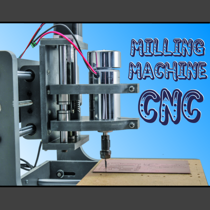
Supplied with a robust chassis (made of plastics) and with three stepper motors, it is provided with a 9,000 RPM electro-spindle, to which it is possible to apply different kinds of milling parts, for the purpose of working wood, plastics, synthetic resins, and for carrying out small engravings on aluminum.
It is not the first time that we deal with numerical control machines for domestic use, that are suitable for milling or for fine engraving, for the creation of mechanical parts, and objects having different shapes – for the purposes of 3D printing and subtractive manufacturing. We did that already when we showed you one of the many transformations of our 3Drag printer, at that time turned into a CNC milling machine, used for the purpose of engraving printed circuit boards and equipped with a Proxxon electro-spindle. In the meantime, we had the chance to try other machines, and in these pages, we will show you a CNC machine that is available in its assembly kit, and that stands out because of the excellent value for money. That was achieved also because of the fact that compact PVC was used for the chassis. The machine has been designed mainly for the purpose of engraving PCBs and plates (such as those for mailboxes, intercoms, doorbells) built it is possible to use it in order to work with wood, plastics (even the POM ones); it is also possible to engrave aluminium plates (at a low depth), but without overdoing it.
As with most of the CNC machines, even this one is supplied with a control board for the three axes and interfacing the parallel port, so that it may be driven by means of software such as the well-known Mach 3 (or the more recent Mach4). The latter is a software that converts the G-Code in pulses, that are directly produced on the parallel port. This could be seen as a problem, because of the port disappearing on the modern PCs, but we already thought to a solution that we will describe in the next installment, and that will allow you to drive it directly from USB (and therefore via all the modern computers).
Someone might object that it should be enough to use a USB/parallel adapter (of those that are commonly found for sale), but it is not as easy as it seems. In fact, the problem is twofold: first of all, since the data is sent in a virtual parallel, it would then be converted to parallel form with a certain delay, or worse, with unequal delays that would bring to movements on the three axes that are not perfectly synchronized. The second reason is that many programs for the CNC control do not natively consider managing via USB ports (but by means of their plug-ins, they do).
Our proposal is instead the one of a hardware that, starting from the USB and taking advantage of open-source software, enables the reconstruction (on the machine) of the command pulses for the CNC control board, thus fixing the temporal inconsistencies of the common USB/parallel adapters.

The machine
Let’s start immediately with an overview concerning this new amateur machine tool, that is composed of very robust and accurate mechanism, of a chassis (that enables a working space of as much as 200x180x60 mm), of an electro-spindle and of an electronic board managing the whole; the power is supplied by a switching power supply as for the board (and therefore for the motors), and by a transformer, followed by a Graetz bridge as for the electro-spindle (therefore the voltage is an unregulated one).
The board (that is powered by the dedicated AC/DC switching power supply) commands the three stepper motors of the NEMA17 kind (200 steps/rev) and by means of a relay it switches the electro-spindle on and off, at the command of the program running on the PC; it is provided with a parallel interface, whose pins are directly connected to the command lines of the three motors’ drivers, therefore that’s EN (enable), STEP (pulses) and DIR (direction). Each one of the three driver channels for stepper-motor enables the functioning of the microstep mode, that is to say, it enables fractional steps; thus it is possible to make the corresponding motor advance – when the pulse on the corresponding STEP line arrives – by 1/2, 1/8 or 1/16 of a revolution. Considering the motor’s resolution, this means it is possible to advance the corresponding axis by 400, 1,600 or 3,200 step per revolution.
The mechanism is a particularly simple one, yet the mechanical parts are robust ones, and consist of side (base sides and side plates) and back (base) walls, on which the plate (where the workpiece will be placed) and the rectified bars (having a 12 mm diameter, they act as rail for the head that supports and moves the electro-spindle) will be applied. The electro-spindle moves on 2 axes: y (side) and z (vertical); both are motorized by means of a stepper motor that – by means of an aluminum joint having a Ø5 mm connection for a drive shaft – makes an endless screw rotate. In the latter, one of the stirrups that impose the movement (that is facilitated by recirculating ball sleeves, having a 12 mm internal diameter) has been push-fitted.
The coupling takes advantage of a tested and refined solution, that enables the automatic reloading, thanks to the preload springs, that have to be calibrated during the assembly. The support for the electro-spindle has a collar having a 52 mm diameter.
The side plates of the mechanism are 15 mm thick, while the moveable plate that supports the working piece measures 240×190 mm and has been made of compact PVC as well; it is moved back and forth by means of the usual stepper motor that drives (via an aluminium joint having a Ø5 mm connection for a drive shaft) an endless screw, coupled to the undercarriage, thanks to the abovesaid mechanism for restoring the play.
The tool holder head and the plate’s bogie both move by sliding on two steel rectified bars having a 12 mm diameter and by means of the usual linear bearings (12 mm recirculating ball bushings).
The threaded rods that make up the endless screws are M8s and have a 1.25 mm thread step, that (still considering the discussion made before, on the subject of the electronics driving the stepper motors) enables a resolution, as for the movement of both axes, of 1.25/200 = 0.00625 mm, corresponding to 6.25 thousandths of a mm! If the microstep mode is chosen, it further grows, but let’s say that we are at values that are more than suitable for any kind of manufacturing.
Please notice that, because of the limited size of the machine, the control board and the power supplies are not applied to the chassis (since their encumbrance would be such to require a very big box) but they must be placed in a box aside, and have to be connected to the motors and to the electro-spindle, by means of electric cables having a suitable length.
Building the mechanics
Well, we believe we made this CNC attractive enough: therefore, if you decided to create it, we will guide you, step by step, and starting from the assembly of the mechanical parts. We used plastics for the chassis, which helps in the realization since it is possible to fix some parts simply by slotting them in (which occurs in factories, as for the recirculating ball bushings) or by means of screws.
The figure shows the whole of the parts that make up the CNC mechanics. Once you have the material, the first thing to do is to create the coupling groups with extension recovery, by taking the 3 parts (plates) that in figure have been identified by means of the number 14, and by inserting two plugs in each one of them (with the help of a hammer), each plug must have the head towards the M8 nut, as shown in the second figure .


Once this has been done, you will have to fix one of the plates that has been so prepared on the element n° 19, by means of two M4x25 TCEI screws, 2 M4 nuts, and as many M4 toothed washers. The same should be done with the elements n° 11 and n° 9, and please pay attention to the fact that with the latter you will have to use 2 M4x30 TCEI screws. You will find yourself in the situation shown in figure, by inserting a spring on each plug.

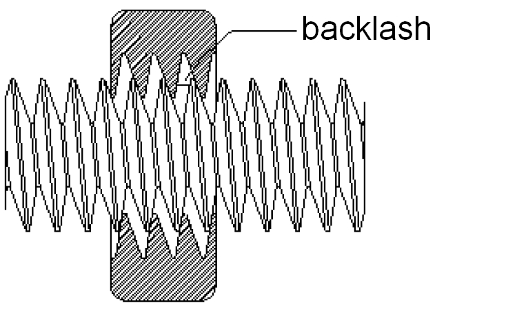
The elements n° 15 will have to be inserted into the plug’s ends and then tightened along with the threaded rods. Please screw the shortest one for a pair of cm in the nut of the tool holder head (detail n° 9), by keeping the shortest and non-threaded rod’s end upwards. Please press the element n° 15 on the springs, so that the plugs emerge of about 2 mm, then please continue to tighten the threaded rod, so to make it enter in the second nut as well, and as shown in the picture. The springs are needed in order to avoid the backlash between the nut and the threaded rod, so to guarantee an extremely accurate realization, even in the most limited movements.
After having inserted the threaded rod in both nuts, you will need to verify that it might still rotate without excessive efforts, so to avoid step losses from the corresponding motor. If needed, please reduce the pressure on the springs.
You will now have to apply some fine oil on the two nuts, so to improve the rod sliding.

Please follow the same procedure when inserting the 315 mm threaded rod in the element n° 11, and the 305 mm one in the element n° 19, so to reach the situation shown in figure, in which all the three play recovery systems have been mounted. At this stage it is possible to mount the group for the guide and the activation of the sliding plate that will host the workpiece: we will start by fixing a stepper motor on the rectified bar n° 5 (back one), by means of the specific M3x12 bolts and then with two 305 mm rectified bars via two M6x20 TCEI screws, but without tightening them to the end, so to allow the alignment at a later time.

Please mount a joint on the motor’s crankpin, and temporarily fix it with a grub screw, so that it does not move, and then please insert the bushings that are mounted on the element n° 18 in the rectified bars, and orient them, after having oiled (with the usual fine oil) the internal side of the bushing, in correspondence with the the microspheres. Please notice that all the CNC bushings have to be oiled before being inserted on the rectified bars, so to facilitate the sliding. Please add the element n° 19 and direct it and continue by laterally fixing the two side walls n° 2 (with the rings pointed towards the motor) to the rectified bar n° 5, and use the dedicated screws, but without tightening them completely. Please then continue by inserting a bearing at the end of the threaded rod and by applying the opposite side (detail n° 4) with the bearing (in which the end of the threaded rod will be inserted) and pointed outwards. Please tighten the screws without fastening them completely and then align all the parts and gradually tighten all the fixing screws, and until the end.

You will now have to align the ends of the two rectified bars with the holes of the front rectified bar, and then to insert 2 M6x20 TCEI screws. Please definitively fix the rectified bars, by gradually tightening the corresponding screws, so to reach the situation shown in the picture.

All that is left to do is to tighten the M5 nut of the threaded rod, by clamping the latter (please place a rubber sheet between them, so to prevent ruining it) and by tightening the end from the external side; when fastening the latter please tighten it until you feel that the bearing is getting fixed, then please loosen it so to make it free to rotate, otherwise it would be pointless.
Now, please place the surface n° 3 (with the holes pointed downwards) on the rectified bars n° 18 and 19 that compose the X axis’ bogie, and align the surface’s holes with those found on the bogie’s rectified bars, and then please fix everything by means of 10 2,8×18 self-threading screws: the base of the plate is ready.

Let’s move on now to the assembly of the pillars that will support the tool holder head: please get the element n° 6 and apply the two 305 mm rectified bars by means of 2 M6x20 TCEI screws, whose points will have to be manually prepared, and then apply the detail n° 12 by making it fit the bushings that have been placed on the rectified bars, and by respecting the orientation shown in figure.

Please also apply the element n° 11, completed with the spiral (please oil the bushings beforehand), and direct it so that the plates’ fixing holes are all pointing the same side. Please insert a bearing at the end of the threaded rod. Now get the other pillar and faster it with the screws that have been supplied (on the rectified bars), after the head of the threaded rod has been inserted in the dedicated hole; please remember to tighten the nut of the threaded rod (with the usual precaution of placing some rubber in between, before tightening the bar with the pliers) for as much as it is needed to leave the bearing free to rotate. Thus you will have prepared the strut and its mechanism.
Please fit a joint on the crankpin of a stepper motor and fix it (by means of the 2 grub screws) at a distance of 7 mm from the body of the motor, and then mount the motor on the right side plate, by means of 4 M3x20 TCEI screws, each one completed with a 3×6 plain washer, and by directing the corresponding connector towards the base of the side plate (the largest side). Please then tighten the side plate by means of the screws that have been supplied.

Now, please fix the plate n° 1 on the back side of the side plates, by means of four 2.8×24 self-tapping screws, and then the plate n° 8 on the Y axis’ bogie, by means of 8 2.8×18 self-tapping screws, and please direct the shortest side (the one with the holes that are closer to the edge) downwards.

You may now assemble the complex that will support the tool holder head and the corresponding movement mechanism on the Z axis; as a first thing please apply the last stepper motor to the element n° 16 and tighten the aluminum joint on the drive shaft. Please then make the bushings that have been mounted on the detail n° 10 (after having oiled them) to slide on the rectified bars, and direct the element as shown in the figure, and add the element n° 9 and the last bearing on the threaded bar.

Please apply the plate n° 17 to the rectified bars by means of M6x20 TCEI screws, and point the bearing outwards and the four holes on the same side of those on the motor plate, so to obtain a result as the one in the picture.

You will then obtain a result such as the one in the figure, that is to say, the strut complex that you will have to apply to the lower part of the machine, by means of the specific screws.

Please place the strut on the chassis’ base and fix it in the most backward position possible, by means of 4 M8x35 TE screws and completed with 2 8×16 plain washers and M8 nut, in such a position to keep the side plates at the same distance from the bottom of the base: with this operation you will have completed the mechanics of your CNC.

All that is left is to assemble the electro-spindle found in the kit or to choose to mount a different electric tool, as long as it is supplied with a round support beam (having a 52 mm diameter) with which to fix it.
If you will be using the one of the kit, please get the collet chuck from the box, and insert it in the specific hole that has been obtained in the clamping ring of the mandrel (please place it with the side having the hole towards the screw cap), then tighten the ring itself until you reach a situation as the one in figure. Please place the electro-spindle in the collar of the tool holder head and fix it by means of the specific screws; you will complete the plate with the stirrups for the workpiece placement.

Wiring of the electric and electronic sections
Once the mechanism has been completed, we have to move on to the wiring. The first operation to be carried out consists in inserting in each stepper motor’s connector the corresponding connecting cable (intended to be self-built), one that has a connector at each end: one for the motor and the other one for the 3-axes controller board. The connectors are of the AMP MODU I type or terminal boxes ending with the said connection. As for the wiring, please stick to the figure, that shows the connections for all the elements of the CNC machine. The power supply’s 220 Vca input and the transformer’s primary input must be powered in parallel, by means of a power cord ending with a network plug. The electro-spindle must be powered by making the positive of the power line coming from the bridge rectifier pass through the relay’s switch, the relay’s coil will be driven by a specific couple of pins that are highlighted by the yellow circle.

The figure shows the machine completed with the electric connections, and whose cables are all in the back, so to prevent them from being a hindrance. The electronics and the power sources must all be placed far from the CNC (please, consequently choose the length of the cables) and protected, so to prevent that shavings and scraps from metalwork may reach them: that would cause dangerous short circuits and the electronics or the DC/DC would be quickly put out of order.

The 3-axes controller board for the machine is already set by default for the control of bipolar stepper motors; anyway, you may change the settings at leisure, by means of a series of dip-switches for each of the three drivers. As a first thing, let’s see the settings for the possible microstep mode: by means of the DIPs 1 and 2, it is possible to set the motors’ resolution (full step, 1/2 step, 1/8 step and 1/16 step), as shown in Table 1, so to advance the axes’ motors of a step fraction, in correspondence for each pulse coming on STEP from the computer.
Table1

The Decay setting (Table 2) concerns the descent front of the pulses for driving the motors, and it may be more or less steep, depending on the expected behaviour; by means of the DIPs 3 and 4 it is possible to set the following modes: FAST, 25%, 50%, Slow. The Slow setting corresponds to a slow voltage decay, while “FAST” corresponds to a quick decay (normal functioning). With steep fronts the motor has no inertia, but if there are recurring stops and restarts, the said setting must be abandoned, in favor of a slow decay (Slow or 50%).
Table2

The relay for the electro-spindle’s powering is commanded in the on/off mode by the specific output of the board, at the command given by the machine’s control software (e.g.: Mach3). Still on the subject of the electro-spindle, please notice that its power is not a regulated one, therefore it is normal that – when under load (that is to say, when the milling machine is in contact with the workpiece and the motor is under strain) – it may even go at a bit more than 40 volt.
Using it along with Mach 3
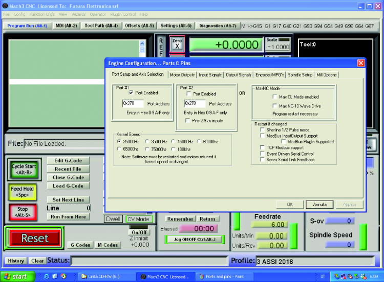
For a correct usage of the 3-axes controller board along with the Mach3 software, it is needed to change the settings, as indicated as follows.
- Please open Mach3 and select “Port and Pins” from the Config menu.
- Select Port#1; the address of the parallel port 1 must be 0x378.
- Set 25000Hz in the Kernel Speed box. With more performing systems, please select a higher value (this influences the motors’ maximum rotation speed).
Please move on to the “Motor Outputs” board.
- Enable the command signal as regards the X, Y and Z axes (Enabled) by clicking in the corresponding box. The green tick will indicate the “active” condition.
- Enter the pin number corresponding to the parallel port in the “Step Pin#” box, for each axis (X=2; Y=4; Z=6).
- Enter the pin number corresponding to the parallel port in the “Dir Pin#” box, for each axis (X=3; Y=5; Z=7).
- Enter the number “1” in the “Step Port” and Dir Port” box, for each axis.

Please move on to the “Input Signals” board and:
- enable the X++, X–, X Home, Y++ limits, etc… as a function of the microswitches that have been actually installed on your machine, and that have been connected to the board’s (5-poles) LIMIT connector;
- set “1” in the corresponding “Port#” boxes, by entering the corresponding PIN number; it may be detected from the parallel port LPT1’s table of pins, that can be found at the box, two pages before this one;
- please tick “Active Low” only if the switch of the corresponding limit closes towards ground (GND) when activated;
- if you are using the emergency button, please tick the EStop entry, and set “1” in the “Port#” box and specify the Pin Number “17”; even in this case please tick “Active Low” only if the switch of the emergency button closes towards ground (GND) when activated.

Please move on to the “Output Signals” board, here you will have to operate as follows.
- Please enable Digit Trig, Enable1, Enable2, Enable3 and Output#1 by clicking in the corresponding boxes. The green tick will indicate the “active” condition.
- set “1” in the corresponding “Port#” boxes.
- Specify the Pin Number that has been assigned to each entry (16 for Digit Trig, 16 for Enable1, 16 for Enable2, 16 for Enable3 and 17 for Output#1).
- Once all the configurations have been completed, please click on the OK button.

Configuration of the parameters of the motors
Let’s move on to the configuration of the parameters for the functioning of the motors; the procedure is as follows.
- Please select “Motor Tuning” from the Config menu.
- Please click on the “X Axis” button on the right, and then set the following parameters:
– “Steps per” (the value for the steps per mm; it depends on the microstep settings chosen and on the type of motor/screw coupling that is used by the machine);
– Velocity In’s or mm’s per min.” (it sets the motor’s rotation speed);
– Acceleration In’s or mm’s/sec/sec” (it sets the motor’s acceleration);
– Step Pulse and Dir Pulse (it sets the duration of the pulse, in microseconds).

Once you the selection of the settings has been completed, please click on the “SAVE AXIS SETTINGS” button.
Please repeat the same procedure for the other axes and then exit the configuration, by clicking on the OK button.
Choosing the voltage power
A special discussion concerns the power voltage of the stepper motors, since generally the greater the voltage, the greater is the engine’s torque at a high speed functioning; with a consequent reduction in the risk of step losses (that may particularly occur in the microstep mode); however, this may damage the driver and implicates an increase in the motor’s vibrations at low revs. The board uses the same power voltage of the motors, therefore there should not be any problem. Please do not modify the said voltage, since it is the one that turned out to be the best one.
Usage notes
Once the machine has been completed, in order to use it please restart the computer and the software, then give voltage to the machine; it will remain inactive until the command is given from the software.
As for the usage, please remember – as a first thing – to keep the boards far and protected, and the same goes for the power supply and the transformer, that we advise to screw to a wood base or to the bottom of a box (if you wish to use it) by means of 3MA screws with nuts. Please also and above all protect the switching power supply, given that its container is a grid, whose holes may let some dangerous elements (such as metal shavings and scraps, coolant) in.
Please remember that the electro-spindle supports all kind of rotating tools whose beam has a diameter of up to 1/8 of an inch, that is to say, 3.17 mm (the collet chuck widens up to that diameter).
Conclusions
In this article we presented a new CNC machine: it’s a very performing one, and one having an excellent value for money; the machine’s control electronics is suitable for the interfacing on a parallel port: however, if you do not possess such a port and if you only have the USB one on your computer, do not miss the next installment! In fact, we will then publish a supplementary board, to be connected between the 3-axes board and the computer. Its peculiarity is that it receives the commands for the three axes from the control software and that it locally generates the pulses that will then be sent to the parallel port.
From openstore
CNC mechanics – kit 200x180x60
Spindle motor 36 Vdc – 300 watt
set board 3 axes + accessories
Switching power supply Mean Well 24 Vdc 150 W
Bipolar stepper motor NEMA 17 – 1,5 A

Will PVC be as robust as metal?
It appears you are using a fixed spindle speed. Does a variable speed add considerable cost?