
[youtube id=”WMfVr5Jlt_E” width=”620″ height=”360″]
Openwheels is fun! See me (Boris Landoni) happily driving the OpenWheels at Rome Maker Faire 2013
Here comes the second post regarding our amazing OpenWheels: the Segway inspired open source and DIY two-wheels vehicle.
For those who stumble upon this post for the first time, please check the launch post here.
Today we will go through the assembly: the sequence has no particular challenges, even for those who have a lack of familiarity with screwdrivers, wrenches, allen screws and whatnot.
Where to Begin

To mount the mechanical structure you must start from an aluminum profile whose dimensions are exactly 30 x 90 mm: it must have two guides that can accommodate M5 square nuts. At the extreme ends of the aluminum profile, side brackets must be fixed but not before having added to each of the two upper guides 3 M5 square nuts (six in total); this must be done before you attach the brackets as it would not be impossible to do it after to insert the nuts. And the nuts are crucial for fixing, in due course, the aluminum platform.

Coming back to the side brackets, these are rather thick (12 millimeters) since they must bear most of the weight of the vehicle and the passenger; the screws must have an adequate strength: in our case we used two M10 screws and four M5 for each bracket.

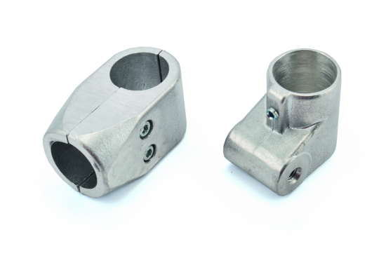
The bracket, in any case, would never be able to withstand the stress that is imposed on the axle of the wheels. For this reason, each bracket is mounted within a collar that is quite sturdy with a central 20 mm hole that can be tightened by means of an Allen screw. The two collars are attached to the inside of the bracket with two M8 screws.

Our vehicle sports 120/70 R12 type tires mounted on 12-inch wheels complete with sealed bearings 15x25x11 mm. Within each wheel a wreath bearing plate should be mounted (with a thickness of 5 mm): this should be fixed to the wheel with 3 M10 screws. This plate is then fastened to a 76 teeth geared ring (typically used fot mini motorbikes) using five M5 screws.


Now it’s the moment to take care of the steel pins of the wheels: on one side they have a diameter of 20 mm and must be inserted into the brackets by using the collars and mounted with the Allen key. On the internal side, the pin must remain perfectly in line with the collar that locks it.

We can now attach the two wheels to the overall body: those are locked from the outside using the self-locking nuts; the terminal part of the pin is in fact threaded. Remember that a special washeris to be inserted between the rim and the nut. To attach the platformthe whole fit the left first and then the right side. During this operation, take advantage of the depth of the hole on the right that allows you to support the platform despite the overhang of the collar; in case the right hole was identical to the left we could not mount the platform. The latter must now be attached to the profile by means of six M5 screws using the square nuts that we had inserted earlier into the two guides (3 for each guide).

Once the platform is set, the nuts are no longer visible so, before this operation, try to position the nuts in correspondence of the relative fixing holes that are present on the platform.


At this point of the process, our vehicle begins to take shape and to have a structure that is quite defined.
The mounting of the motors and chains
The two engines must be mounted under the footboard, on the side, by using two support plates which in turn must be fixed under the platform. The two plates have special slots that allow the parts to flow before fully locking the platform in order to optimally tension the two chains


But, let’s proceed step by step. Each engine has four M6 threaded holes used to fix it to the plate by means of four countersunk screws of the same type. The engine/bracket set is to be fixed under the platform where there are four holes in coincidence of the four slots of the flange: this lets suitably adjust the tension of the chains that will mount immediately after. The flanges are fixed to the platform with four M6 screws and self-locking nuts of the same type. Chains are provided to measure together with the false mesh. Apply the chain between the geared wheel and the pinion of the motor, adjust the tension and insert the plug for the closure of the chain.

Besides the correct chain tension, also try to make the two traction blocks as symmetrical as possible; in other words, try to place as much as possible the two flanges in the same position.


The Handlebar
The handlebar shaft is used to control the pace of our vehicle: tilting it slightly to the left, the vehicle turns left, by tilting it to the right, the vehicle turns in that direction. To accelerate and decelerate (or stop) is instead necessary to push the handlebar forward, that is, since the handlebar is integral with the platform you need to move your body weight forward or backward (of course with the help of the handlebar).

To put the 90 cm rod (that is made of 2 mm thick aluminum tubing with an outer diameter of 30 mm) in place, we must first mount, at the front of the platform, two specific Delrin made supports with a thickness of 20 mm by using two M8 screws each. The rod has a metal bottom support that is fastened to the two Delrin parts through a partially threaded screw M12 x 100mm (with socket hexagon cylindrical head).

The bottom bracket has two threaded holes on the side in which two screws are inserted; between the screw head and the platform two springs are mounted to allow the rod to remain in vertical position but also to tilt slightly to the right and left.Normally the springs are not visible because they are hidden by two side gussets.
To ensure that the movement of the handlebar produce a signal capable of controlling the electronic control unit, the easiest solution is to use a 10 kohm potentiometer (or a slightly different value) whose pivot is fixed to the head of the screw while the body is locked to the support rod of the handlebar. Even in this case, the photos and drawings will let you know better how to mount this section.

The handlebar is to be fastened on the head of the rod: it’s nothing but another, approximately 44 cm long, piece of tubular aluminum rod of the same type. The rod making the handlebar should be closed with plastic plugs at the ends while to lock it on the vertical rod you must use a special joint – to be positioned at the center – that has two Allen screws for locking.

At this point the mechanic is pretty much over, so we try to keep it upright and see what happens.
Obviously, the vehicle will immediately rotate as the center of gravity is above the axis of rotation of the wheels. Let’s now try to mount the last electro-mechanical piece (the batteries) and see what happens. As indicated in the box, our vehicle uses two 12V 20Ah batteries connected in series so as to obtain the voltage of 24 volts suitable to feed the two engines. Each battery (weighing about 7 kg) is fastened by means of two flat plates under the platform, in a central position, starting from the central aluminum profile.

As you can see in the pictures the batteries should be turned in to the terminals towards the center of the structure so that the connections are as short as possible. The currents involved are very high (especially during the cues) and therefore the cables must be of a suitable diameter and very short.
Once the batteries are attached, let’s now put our vehicle upright again. Magically everything will remain in an upright position because the center of gravity which, thanks to the weight of the batteries, is now under the center of rotation of the wheels.

Now, if we try to climb the vehicle we risk hurting ourselves: our weight, indeed, moves the center of gravity again above the center of rotation and therefore the system is no longer in balance.
Here, the first thing that the electronic control circuit must do (thanks to a set of sensors) is precisely to operate engines (and consequently the wheels) to counterbalance this effect as precisely and efficiently (with less power consumption) as possible.
Once we obtain this feature, the vehicle must be able to move back and forth while remaining in equilibrium even in these conditions. The movements of the body weight on the platform must be tracked by the sensors to move forward at gradually higher speeds, and to stop at some point (OpenWheels has no brakes) as well as to move backwards.
Leveraging the handlebar angle (measured from the potentiometer) instead we’ll get the signals to change the direction.
Download the quote files (provided under CC-BY-SA 4.0 license)
Next steps
We are moving forward with the creation of your Open Source Segway alternative Openwheels: next post will be about the electronics! So stay tuned and register to our feeds and social channels to get informed.

Hi guys,thank you for a nice piece of intereting thing, which will make me bussy for a long time :-)
I have one question, I still cannot understant how is made the connection between handlebar and potenciometer in the bottom part. There are two springs which are in touch with bar collar screw.This is for stabilization the stick in vertical position.But how is connected the collar to the potenciometer????
Hello there, wonderful project. Is there any way to get also the thickness of the different aluminium parts?
Thanks!
hello there great project,
can you give me the complete measurements of this Project ?
there are only the basic measurements how long and how broad the parts are.
my E-Mail : leonard-renneberg@hotmail.de for answers about Feedback i would be happy :)