A scalable board to prototype motion control applications for automatic balanced robot or any other robot on wheels.
It was the 2013 when we presented a control board to make a clone of the famous SegWay: the OpenWheels project. In recent years, the focus on systems to stabilize unstable ones grew up sensibly. Just look at the many projects proposed on the net to see how many people has ventured into making simple (or not) unstable robot, better known by the English term “balanced robot”. We have improved our first project by exploiting new technologies on the market, so a new board was born, the OpenWheels2.

It is an all-in-one board to control movements on any of your robotic projects. The board we are going to present is in fact equipped (and expandable) with everything needed to make even complex robot, so not only balanced robots.
The project was forked from the SegWay clone control board to control instead a balanced robot that we will call Personal Robot.
Features
The main innovation is on the processor, which passes from an ATmega328P to ATmega2560 maintaining compatibility with Arduino and considerably increasing the available pins and UART modules, very useful for the connectivity features. The IMU module has better performances while the power MOSFET stage is unchanged. The new board has the same dimensions as before and the same connectors, so it is an easy upgrade for those who have OpenWheels v1.
The new board features are:
- compatible with Arduino 2560;
- ready to use XBee and Bluetooth modules;
- supports up to two DC motors with a maximum current of 20A (peak 30A);
- has input power voltage and current sensors;
- encoder input connector;
- supports both analog and digital IMU modules

Wiring diagram
Describing the electrical diagram, let’s start from the power supply stage: the voltage applied to + and – PWR contacts goes to ACS758 chip, that measures the absorbed current, then to the R10 / R11 divider (needed by the chip to measure the battery voltage), to the fuse F1 and to reverse polarity protection diode, which precedes the voltage switching regulator LM2576 (U2) used to lower the voltage to 12V. The board is designed to be powered at 24V and without any changes, accepts down to 11,5V; bypassing the switching, it is possible to accept the lower voltage. On the 12V line there are two linear voltage stabilizers which respectively provide the 5V and 3.3V lines necessary to the microcontroller and IMU module. The two motor drivers, in H-bridge configuration, feature the IRS2184 integrated circuits which uses a capacitive voltage pump to obtain a higher voltage than the power supply one, so as to drive the MOSFET gate.
For each engine, we use two IRS2184 and four MOSFET driven by two signals only: one is the “driver enable (shutdown)” signal and the second is the PWM control signal configured in locked-antiphase mode.
In this mode, the PWM signal goes to both ends of the H-bridge but in phase opposition: so the wheel remains stationary with a 50% duty-cycle. The wheel rotates at the maximum speed in one direction with a duty cycle of 0% and the maximum speed in the opposite direction with the 100% duty-cycle. In case of the balanced-robot, where the wheels have continuous direction changes (to maintain the vertical position), this mode allows the power MOSFET to work with a duty-cycle of about 50%, avoiding very rapid pulse signals as happens in the classic sign-magnitude mode, where a signal is controlling direction and another is the PWM.

With these drivers, when the robot is in the equilibrium position the PWM signal has a very low duty cycle and the direction signal changes continuously. This is not an issue with motors that absorb few hundred milliamperes, but with engines which absorb several amps that can become a real problem. The MOSFETs used in the project are the AUIRF2804 type, supporting up to 200A pulse currents and 10A continuous current, without heating appreciably. We have in any case a fan connector if you prefer the forced cooling.
We have three protection fuses onboard: one by 1A to protect the control circuits and two on the motor power lines; the latter should be dimensioned to interrupt the power circuit in presence of excessive current peaks, usually happening when motors start moving. The microcontroller is an ATmega2560, the same mounted on Arduino Mega, which, compared to ATmega328 (Arduino ONE), has more pins and four serial UART interfaces.
The analog inputs are used for current and supply voltage reading, for the steering potentiometer (if present) and for the analog accelerometer and gyroscope, if they are present. There is a BAR connector to connect a button controller and a LCD display according to Table 1, and a connector for the steering potentiometer (Table 2).
Table1

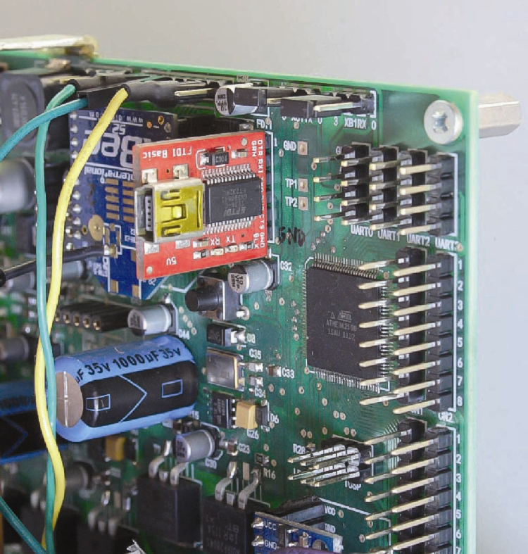
On the board there are two sockets for the MMA7361 analog accelerometer and for the LPR403 analog gyroscope, and another one for the XBee module; four connectors for the four UART TX/RX signals. Serial0 is the main serial and it is connected to FDTI connector, which can be connected to a USB / serial converter useful for microcontroller programming, while the Serial3 is used for telemetry and is connected to the XBee module socket via XB1TX and XB1RX jumpers; Serial1 is used for the LCD display.
Table2

In the board bottom part there is the InvenSense MPU-6050 digital IMU module connector and that for I²C bus communication port, which connects to any other digital IMU module. There is also a connector for the two encoders input signals and one for the external modules power supply.
All the ATmega2560 unused pins (for this project) are still made available through the CN1, CN2, CN3 and CN4 connectors, if you want to expand any feature. Finally we find the ICSP connector, which, as we shall see, will be used to load the bootloader on the microcontroller.
Different LEDs have been implemented to report the operating status, as shown in Table 3.
Table3

The board layout description is done, now let’s move to the practical example by make a really complex balance robot, very stable even in the most critical situations.

The robot mechanical part
We start from the mechanical parts, printed with our 3Drag and appropriately designed to house the electronics. On the base we’re going to fix motors, battery and OpenWheels2 control board. We will fix also an aluminum rod we can use as a support for a small tray put on robot’s top and that can contain objects or, as we did, drinks; nothing prevents you from applying anything else.
The control board should be connected to the following devices:
– 2 motors with encoder and wheels (2846-BALANCINGBOT);
– Li-Po Battery 1800 mAh / 11.1 V (5400-LIPO1800);
– male / female connector (7300-TCONNMF);
– unipolar switch button (8220-8701);
– unipolar deviator lever for c.s. at 90 ° (8220-TS-8);
– 2 XBee 2mW modules, Series 2 (6168-XBEE2MW);
– XBEE USB EXPLORER (6168-XBEEDONGLE2);
– Bluetooth DAGU controller module (2586-DG010);
– 3-axis accelerometer + 3-axis gyro (2846-MPU6050);
– converter FTDI USB / Serial 3.3V and 5V (7300-FTDI5V);
– fuse (F2) 1A;
– fuse (F1, F3) 5A.

The XBee modules and Bluetooth are used for telemetry. The components are all available in our store.
If you were using a long rod for the tray, it may be necessary to provide a small weight of about 100 g to balance the weight at the rod base, due to motors and battery; we could have placed the batttery high up, but that would require long cables that would have introduced a deleterious electrical resistance.
Although it is not intuitive, the weight placed on top enhances the stability while minimizing small oscillations due to the materials weakness.
At this point, you can fix the motors to the 3D printed substrate, their related wheel and the electronic board, as shown in pictures; The only precaution is to fix the board properly. As regards the electrical connections, we must be very careful, especially for engines that have the encoder incorporated; refer to Figure.

There is a switch (connected as shown in Table 4) that will be used to activate the robot and a button to reset the alarms. If you want, you can put a power switch in series to the battery shows the wiring.
Table4

The firmware
The firmware is derived from the original OpenWheels one, improved and enriched with new features. To upload it, you must install a bootloader on ATmega: we can use a dedicated programmer or a common Arduino board used as a programmer.
In the latter case, run the Arduino IDE and load ArduinoISP.ino , set “Arduino Mega2560 or Mega ADK” as target board in Tools menu> Arduino type, then set Arduino as programmer (Tools> programmer> Arduino as ISP).
Table5

At this point start the upload with Tools> Write Bootloader. When done (requires a few minutes) disconnect the programmer and connect to the board directly from the PC via the FDTI connector with the aid of a USB / Serial converter: your board will be seen on the IDE as an Arduino Mega.
To verify that everything is working, load the Blink.ino example sketch and check if the LD6 LED flashes.
For now, you can omit the XBee module and ensure that the IMU module is correctly installed; you can then do some tests to make sure everything works (we recommend you do so before installing the board and make connections).

Let’s test the sensors with the sketch named PersonalRobot_TestSensor.ino available together with the project files on www.elettronicain.it . The collected data will be displayed directly on Arduino SerialMonitor in a raw format, without any post-processing. With a simple jumper you can simulate the buttons by shorting P1, P2, P3, PStart inputs to the GND pin; connecting a serial display to BAR connector + 5V, GND, LCD pins you can test it. Please note that the LCD display is supported in both hardware and software, but not used in this project because, as we shall see, we expected more for the data display systems. If the motors are connected, you can test them by loading the OpenWheelsTestMotorV2.ino sketch. Motors are controlled directly by typing characters through the SerialMonitor. The important thing to check is that motors rotate in the correct direction and that the robot moves ahead when the wheels spin clockwise.
One of the most important innovations over the previous version is the use of a digital IMU module based on Invensense MPU-6050, which features an accelerometer and a gyroscope both three-axis, in addition to a suitable microprocessor to process the acquired data. The precision and resolution are greatly increased and the noise level, main villain for any accelerometer, here is very low.

This module which is often found on the market as breakout board with the GY-52 part number, is an excellent compromise between performances and cost; also its I²C communication interface is perfect for pairing with Arduino. As always, the accelerometer and gyroscope data must be merged together in order to minimize the inevitable gyroscope offset drift and to limit the accelerometer noise; between the various solutions, the complementary filter was effective and easy to implement.
The firmware required to operate our robot is called PersonalRobot_V10.ino and can be downloaded together with all the other project files. Let’s start by saying that in the robot, the control board is placed vertically, but nothing prevents you to place it horizontally; in which case you must configure the firmware uncommenting the right code instruction:
<span style="font-weight: 400;">// horizontal board</span>
<span style="font-weight: 400;">//Wire.write(MPU6050_ACCEL_YOUT_H);</span>
<span style="font-weight: 400;"> </span>
<span style="font-weight: 400;">// vertical board</span>
<span style="font-weight: 400;">Wire.write (MPU6050_ACCEL_ZOUT_H);</span>
The sketch is divided into blocks, each of which has a distinct file according to its function;
PersonalRobot_V10.ino contains the main code that calls all the necessary functions.
The main loop contains only the function calls and the cycle time measurement (see Listing 1).
Listing1
void loop()
{
time2=micros();
dt = float(time2-time1)/1000000.0; //cycle time
time1=time2;
SoftStart();
EstimateAngle();
EstimatePos();
Status();
PID();
SetMotor();
SetZero();
Telemetry();
if (digitalRead(P1_pin) == 0)
{
// reset error
statusFlag=0;
errorIMU=0;
Integral=0;
encoderCounterLeft=0;
encoderCounterRight=0;
}
delay(18); //about 50Hz
}
The entire stabilization cycle lasts approximately 2 ms, but with a delay function we bring it to a more reasonable 20 ms, or 50 times per second. The telemetry impacts heavily on the cycle time, which in any case is recalculated in each iteration. In EEPROM.ino file there are the functions required to read and write the ATmega2560 EEPROM: in our case, all of the PID control parameters and sensors offset values.
IMU.h file contains functions that allow you to initialize the sensors, to measure offset and actual values. In applications of this type, the firmware is very critical and contemplates various parameters that must assume a precise value depending on the installed hardware; it is sufficient to modify, for example, the robot rod height to change its center of gravity and its moment of inertia; Imagine what can happen for example by replacing motors or varying some weight.
In addition to the usual PID control parameters, there are some less critical but equally important ones that make the difference between a robot that is vertically stable and one that remains vertically even if you apply a weight suddenly; in particular, in MPU6050_init () function check the MPU6050_write (MPU6050_CONFIG, 0x04) instruction that sets the accelerometer and gyro data filtering to 20Hz frequency (parameter DLPF_CFG = 4) ensuring a cleaning read from the unwanted noise.
If the robot had been smaller and you need faster reaction times, this value would necessarily rise (lower DLPF_CFG parameter). Another relatively important parameter is the cutoff frequency of the complementary filter that merges the sensors readings.
The line that defines it is this:
float Comp_Filter_Constant = 0.01
lower values slow down the angle measurement (but attenuate the noise more) while higher values allow to obtain faster angular measurement, but more affected by noise.
The section that manages the encoder is contained in Encoder.ino file, an ex-novo implemented section for OpenWheels2: in balanced robot, it is important not only the vertical stability, but also the keeping of a precise point in relation to the ground, otherwise it can happen that the robot moves randomly in the room because of some sensor drift. The encoders provide information about the wheels’ rotation, so you can evaluate when the robot moves. Using the encoders on both wheels we can also obtain information on the rotational difference between the two, which would lead the robot to rotate on its vertical axis because of motors behavior light differences.
To avoid that, we set the variables WheelsPos (DEG), which provides the position of the wheels in degrees, WheelsVel, which provides the wheel rotation speed in degrees per second, and the encoderDif, which provides information on the rotation difference between the wheels in degrees.
To each of the two encoders is associated an interrupt:
<span style="font-weight: 400;">attachInterrupt (0, EncoderLeft, </span><span style="font-weight: 400;">
 </span><span style="font-weight: 400;">FALLING); // pin 2 int0 encoder (ENC1)</span>
<span style="font-weight: 400;">attachInterrupt (1 EncoderRight, FALLING); // encoder pin3 int1 (ENC2)</span>
To find out if the wheel is turning clockwise (and then increases up the counter) or counterclockwise (decreases the counter) we have to use both the quadrature signals provided by the encoder. The second signal is then connected to a board digital input and when read during the interrupt, it provides info on the wheel rotation direction (see Listing 2).
Listing2
void EncoderRight()
{
// If pinA and pinB are both high or both low, it is spinning
// forward. If they’re different, it’s going backward.
if(PINL & 0b00000010)
encoderCounterRight++;
else
encoderCounterRight--;
}
The file named PID.ino is the heart of the whole system, because it contains the lines of code needed to stabilize the robot (see Listing 3). It is, ultimately, a calculation which takes into account the different contributions according to parameters which the user must enter in a very precise way. Let’s look at the meaning:
– Pval, controlled by the parameter KP, is the proportional value (the more the robot tilts the more is necessary to compensate);
– Ival, controlled by KI parameter, is the additional value and is used only in SegWay clones to control the function to move ahead at a constant speed keeping the handlebar in rest position
– DVAL, controlled by the parameter KI, is the derivative value and its effect is felt as much as greater is the tendency to fall down;
– Ppos, controlled by KO parameter is the proportional value for positioning; the greater this value, the greater the accuracy with which the robot maintains its ground relative position;
– Pvel, controlled by the parameter KV, is the value which, together with the PPOs value, avoids that the robot moves away from the initial position.
Listing3
Pval = float(KP) * Angle;
Ival = float(KI) * Integral;
Dval = float(KD) * Gyro_Rate;
Ppos = float(KO) * wheelsPos;
Pvel = float(KV) * wheelsVel;
drive = Pval + Ival + Dval + Ppos + Pvel;
drive = drive * VBatAlim/VBatLevel; // for compensate Battery level
drive = constrain(drive, -250.0, 250.0); //limit drive values
In the telemetry software you can set the STEER parameter, useful for setting the steering sensitivity when the project is a Segway clone.
An additional parameter called Kdm allows to keep the robot original orientation compensating for differences in wheel rotation. Obviously, the last three values must be reset to zero in all cases in which you want the robot to move, perhaps because remote-controlled.

By analyzing the code there is also a line used to compensate the battery charge level:
drive = drive * VBatAlim / VBatLevel
In fact, the actual power transferred to wheels depends on the level of battery charge and can be different from the expected (calculated) power level. Since we don’t want the robot to behave differently according to the battery charging level, this parameter is very important. The Motor.ino file (Listing 4) contains settings and functions to manage the engines, first of all the setting of Atmel internal registers, in order to control motors with a PWM signal at high resolution (10bit) instead of the 8bit used by default in Arduino; also the PWM frequency is set to 16 kHz, ensuring a more fluid and silent movements. Also in this section, there are two other parameters denominated steerSensibilty and speedSensibility that, as suggested by their names, define respectively the steering angle and the speed sensitivity, if the robot is remotely controlled (Listing 5).
Listing4
void initMotor()
{
pinMode(ShutDown_pin, OUTPUT);
digitalWrite(ShutDown_pin, LOW); //ShutDown driver at startUP
pinMode(PWMLeft_pin, OUTPUT);
pinMode(PWMRight_pin, OUTPUT);
// Phase and Frequency correct PWM on TIMER1
//PWM_frequency = (16000000)/(2*Prescale_factor*ICR1)
//ICR1=(16000000)/(2*Prescale_factor*PWM_frequency)
// ICR1=400 fPWM=20000
// ICR1=500 fPWM=16000
// ICR1=666 fPWM=12012
// ICR1=1024 fPWM=7812
TCCR1A = _BV(COM1A1) | _BV(COM1B1) ;
TCCR1B = _BV(WGM13) | _BV(CS10);
ICR1=500;
// **********************************************************************
// limit for driver compatibiliti (5% di ICR1A) < drivePWM < (95% di ICR1A)
// stop motor driver=stallMotor=ICR1/2;
// **********************************************************************
maxPWM = float(ICR1)*0.80/2; //0.95
stallMotor=ICR1/2; //25
OCR1A = stallMotor; //0=0% ICR1/2=50% ICR1=100%
OCR1B = stallMotor;
}

In this section you will also find the motor dead zone compensation, which is the voltage level below which the wheels do not turn for internal friction and losses. For example, if the robot needs a 5% engine power to be stable but the corresponding voltage level is within the dead zone and is not sufficient to overcome the friction, the wheels will not turn. This results in the robot tending to fall down thus requiring a further correction, causing an uncertain balance. A simple test with the robot leaning against the ground will allow you to determine the minimum power value needed for the robot to move. The code line that defines this parameter is:
int deadZoneMotor = 10.
The section SerLCD.ino is not used and has been left for compatibility with previous hardware.
Listing5
void SetMotor()
{
Steer = steerSensibilty * float(int(dataX)-127);
Speed = speedSensibility * float(int(dataY)-127);
drivePWM_L = int( (drive*goStart) - Kdm*float(encoderDif) + Steer );
drivePWM_R = int( (drive*goStart) + Kdm*float(encoderDif) - Steer );
// compensate motor dead band
if (drivePWM_L>0) drivePWM_L += deadZoneMotor;
if (drivePWM_L<0) drivePWM_L -= deadZoneMotor;
if (drivePWM_R>0) drivePWM_R += deadZoneMotor;
if (drivePWM_R<0) drivePWM_R -= deadZoneMotor;
dutyCycleLeft = stallMotor + drivePWM_L;// + Steer;
dutyCycleRight = stallMotor + drivePWM_R;// - Steer;
dutyCycleLeft = constrain(dutyCycleLeft, stallMotor-maxPWM, stallMotor+maxPWM);
dutyCycleRight = constrain(dutyCycleRight, stallMotor-maxPWM, stallMotor+maxPWM);
OCR1B = dutyCycleLeft; //set PWM SX 250+-250
OCR1A = dutyCycleRight; //set PWM DX 250+-250
}
The telemetry.ino file contains the functions used for communicating with the board; specifically, to request data or set of parameters. In any case, it is the external equipment that must request for data, as Openwheels2 don’t send any data automatically; see, in this regard, Table 6.
Table6

Additional fine tuning parameters are used to control the operating state and alarms; as an example, these three voltage values related respectively to the maximum, minimum and nominal power voltage:
<i><span style="font-weight: 400;">float VBatLmax = 12.6;</span></i><span style="font-weight: 400;"> </span><i><span style="font-weight: 400;">// Max batt Volt</span></i>
<i><span style="font-weight: 400;">float VBatLmin = 11.5;</span></i><span style="font-weight: 400;"> </span><i><span style="font-weight: 400;">// Low batt volts</span></i>
<i><span style="font-weight: 400;">float VBatAlim = 11.8;</span></i><span style="font-weight: 400;"> </span><i><span style="font-weight: 400;">// Nominal batt Volt</span></i>
<span style="font-weight: 400;"> </span>
These values are used, as well as for alarms, even for the engines power compensation function.
Notice that because of the power drivers, the minimum operating voltage cannot be less than 11.5 volts, worth the impossibility of bringing the MOSFETs in the ON state. Another value is the maximum current before engines safety shutdown.
The function operates in about 20 ms: it’s not the same speed of fuses, but it offers good protection in most cases:
<i><span style="font-weight: 400;">float IBatMAX = 3.0;</span></i>
<i><span style="font-weight: 400;">// IBAT MAX for MOTOR shutdown</span></i>
Additional protective measures impact the variables shown in Table 7.
Table7
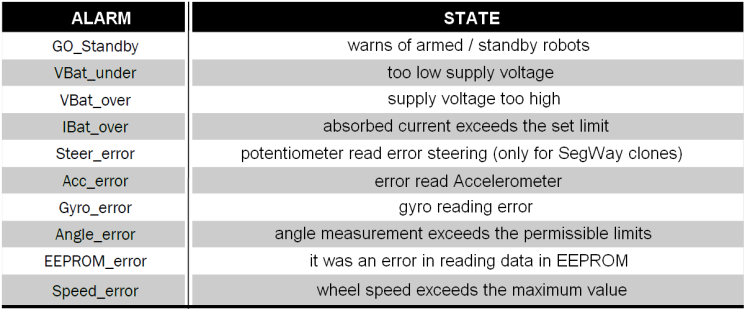
The first bit of statusFlag does not contain an error, but indicates whether the robot is in standby or armed state, i.e. “up and running”. This state change is operated by the switch.
In the standby state all systems are fully functional, including telemetry, but the driver is disabled and the wheels cannot turn: you can then manage the robot without doing damages.
LD6 LED flashes in case of an error state; you can reset the alarms by pressing the reset button (or by remote control) only.
Given the complexity of setting parameters and the need to visualize the operating condition, we have implemented a special software (OpenWheelsGUI_V20) for the remote management of all major operations, allowing you to view all the telemetry data graphically. The software was written by using Processing, because it is a development environment that supports several operating systems.
In order to use the configuration software, you have to install the USB / Serial converter, so as to communicate with the board using your Serial3 microcontroller interface, available on UART3 connector: simply wire the TX, RX and GND lines; the + 5V is not necessary because the board has its own power supply. The software is very intuitive and once executed, simply select the serial used for communication: the software will, at regular intervals, poll the robot.
All major data is displayed: the tilt, the current consumption and the engines power are also visible on a chart. Red fields allow parameter entry by simply dragging over the mouse pointer. The RESET button allows you to reset all the alarms, OFFSET allows the sensor offset check, READ commands the reading of currently used PID parameters, WRITE sends the parameters, while the SAVE button saves in the microcontroller EEPROM memory the currently used PID parameters.
Wireless telemetry configuration
Wireless telemetry / configuration is much more convenient, since the robot complete control can be done in real time while it is in equilibrium, it is therefore easy to modify parameters on the fly and see the real-time behavior.
To reach the highest telemetry range you need the XBee module: also the 2mW series 2 is enough for our application. XBee modules are pre-programmed before using, so you need to download the Digi_XCTU software.
For our needs, the two modules communicate in transparent mode. In this mode, the two modules (and only them) behave as a wired connection. First, put one of the two XBee modules into the USB dongle and set the ID = 0 and MY = 0 parameters, then read the SH and SL values. At this point insert the other module, read SH and SL value and write on the DH and DL fields the SH and SL values read on the previous module: DH = SH and DL = SL. Exchange again the module in the USB dongle and write on its DH and DL fields the SH and SL values read on the second module. In this way the destination address (D) of the first module will coincide with the physical address of the second module (S) and vice versa. At this point the two modules are ready to communicate. Do not forget to set the two XB1TX XB1RX jumpers to “3” to link the module with the Atmel Serial3 used for the telemetry.

Install the second module on Openwheels2 and let the first connected to the PC, start the OpenWheelsGUI_V20 software and select the serial port on the XBee dongle: immediately start reading parameters. You can view all the operating parameters including a real-time graph of the tilt angle, the engine power level and current consumption. A text line at the bottom shows the operating status and any error messages.
There is also the possibility to set Bluetooth telemetry: in this case it is necessary to equip the Openwheels board 2 with a BT module.
To avoid modifying the sketch we used a Bluetooth module that once configured doesn’t require additional instructions to operate, as the Dagurobot DG010 module, which is always connected to Serial3 through UART3 connector.

This module is sold preconfigured to work in SPP (Serial Port Profile) mode at 9,600 bps; the SPP enables the module to transfer data serially exactly as a cable would do, similar to XBee transparent mode.
For our application, you must set 115 kbps communication speed to “Probot” device name. To do these config you must interface the module to the PC via the USB / Serial converter.
Use a software that can send strings via the serial interface, like CoolTermWin or Arduino SerialMonitor, setting the baud rate to 9,600 bps.
Send therefore the AT string without adding any newline or carriage return: If the module responds with OK means that the communication is established. Change the device name with the
AT+NAMEPRobot
command and the communication baud rate with the
AT+BAUD8
command. The module is now configured and ready to operate in the required mode. The PC must have a built in Bluetooth module or you must use a BT dongle.

Commissioning
With the telemetry software running, you should set all of the PID control parameters to zero and proceed to sensors offset setting; position the robot exactly in balance in a stable and vibration-free status and press the OFFSET button: calibration is automatic and requires two seconds. To avoid having to repeat the operation at every power on, the parameters are saved in the micro permanent memory. Now switch the robot from stand-by to “Go” and reset alarms; you just need to set the right PID parameters to achieve stabilization. There is no reliable and safe procedure to determine the correct parameters immediately; you just need a lot of patience and several trials to come at a satisfactory stabilization. The ideal procedure is that, starting with all parameter at “null”, you just lift the KP parameter until the robot does not begin to oscillate; then lower the KP value so that the robot does not oscillate, then set the KV value. Just with these two parameters, you should ensure the stabilization and only later you will raise the KO value to ensure that the robot maintains its position. Later you can try to raise the KD value to see if the stabilization improves.
With our robot, we simply set: KP = 160, KO = 5 and KV = 12 (the remaining parameters are zero).
Remote control
We can also remotely control the robot’s movements: the basic philosophy is to “fool” the robot by making it believe it is perfectly balanced, while it is actually slightly (we are talking about tenths of a degree) inclined, therefore tending to fall.
It is sufficient to increase or decrease the Pvel variable so that the robot moves back or forth; to make it steer, we need to modify the two motors PWM value by increasing the first and decreasing the other, so that the sum remains constant. As already mentioned the KO and Kdm parameters must be set to zero otherwise the robot will interpret the movement commands as noise and it will try to compensate. Also in this case we have written a PersonalRobotGUI_V10 custom software which allows to keep the main parameters under control and at the same time to control the movement through a simple virtual joystick, mouse operated.
Android Control
We also developed an Android app, written thanks to Processing IDE capability of managing multiple development platforms, to control the robot with the smartphone. The app is not particularly complex or aesthetically sophisticated, but serves the purpose, receiving telemetry data and sending the virtual joystick data, implemented on the display and easily operated with thumbs.

The App was written for a Samsung S4 smartphone with FHD AMOLED display, so we preferred a very dark background to prevent excessive power consumption during operations. To use your smartphone as the remote control you need to install the PRobot.apk you will find among the project files. Since the apk doesn’t come from the Google Play store, to install it you have to enable the installation mode “from unknown sources” usually available in the android “security” settings.
First, you must pair the Bluetooth devices (password is 1234); then you can run the app, which is configured to search and connect to PRobot device among the paired ones. The app will display the telemetry data and you can operate the joystick to control the robot.

Download all files
From openstore
XBee 1mW Trace Antenna – Series 1 (802.15.4)
XBee Series 2 module 2 mW (ZigBee Mesh)
XBEE EXPLORER USB (without XBEE)
Set: 2 wheels with motor + encoder and brackets
