
Controller with stepper motor feedback able to dynamically check the shaft positioning and prevent possible step losses.
Who has never happened to launch a complex and long 3D print, maybe a job of hours or dozens of hours, to be absent and discover that, when the job was almost finished, the printer engines lost a few steps with the result of having the ruined object printed badly with layers not aligned with each other? Unfortunately, it is not uncommon, and the surprising (or irritating…) thing is that it happens almost always towards the end of printing, causing considerable waste of material and time. Since the vast majority of 3D printers on the market use open-loop controlled stepper motors, this is unavoidable because the controller has no way of ascertaining whether the order given is correctly executed by the motor, i.e., whether the rotor advances one step with each pulse sent.
To make up for this shortcoming, we decided to make a controller, called Motorfish, able to locally manage (in close contact…) a stepper motor equipped with encoder, then to operate a reaction (or feedback) control able to verify that the angular position of the stepper motor shaft is consistent with the driving impulses.
Before analyzing the wiring diagram, it is advisable to clarify how the two types of motor position control, which are open-loop and closed-loop, work.
In the first case, also known as open loop, the controller sends a command to the engine without confirmation of the actual movement; if the engine has been unable to move for any reason (for example if the printhead has encountered an obstacle or if the required movement speed is too high), the error is maintained and accumulates with any subsequent errors.
The electronics has no way to know the real position of the engine, with the result of having prints that may be “staggered” from halfway through the job.
In closed-loop control (closed-loop, Fig. 1), a movement command is given to the motor, but in this case, a position sensor on the motor can provide a “confirmation” of the movement that has occurred or an error signal if this is impossible. The controller can then decide whether to stop everything, try again or go ahead and try to correct the problem later.
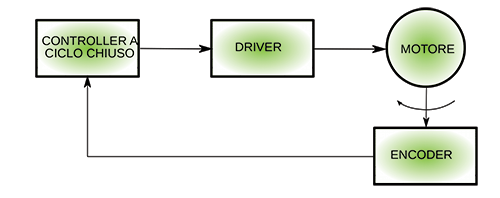
Fig. 1
The closed-loop system has several advantages over the former; first, the displacement no longer depends on the type of motor, but only on the resolution of the motion sensor (an encoder, usually). So we will no longer be forced to work by discrete steps (steps) or micro-steps, but we will be able to have a continuous operation of the motor, with less mechanical vibrations.

A second advantage is that, since we are not at risk of losing position, we can “push” the engine to the maximum without worrying about anything or almost anything; if the engine fails to follow the commands, the electronics will notice and can remedy it, either by reducing speed and/or acceleration or by correcting errors.
The third advantage is reduced power consumption. In an open cycle stepper motor, we are obliged to maintain a high current in the windings even when the motor is at a standstill, to avoid undesired movements perhaps due to masses in rapid deceleration or involuntary tampering with the printer plate; in the closed cycle motor when it is not moving, we can reduce the current in the windings to zero, sure that in case of involuntary movement the electronics will be able to correct the position immediately.
Last but not least, there is the possible simplification of the engine itself. It will not be our case since we will use a stepper motor anyway, but if you want, you can replace it with any other type of motor, even brushless or brushless, simply changing the electronics and/or the control software. As we will see later, our MotorFish is also able to control a brushed motor by simply modifying the controller software. The brushed motors use only one “winding” (not so, but this is what appears on the outside), and our driver can drive up to 2 of them; unfortunately, it will not be possible to drive 3 windings motors.
Components List:
R1, R2, R8: 1 kohm (0603)
R3: 1 Mohm (0603)
R4, R5: 0.2 ohm (1210)
R6: 1.02 kohm (0603)
R7: 3.4 kohm (0603)
R9: 10 kohm (0603)
R10, R11, R12, R13: 470 ohms (0603)
R14, R15, R16, R17: 2.2 kohm (0603)
C1: 4.7 µF ceramic (0603)
C2, C3, C4, C5, C6, C8, C9, C10,
C11, C12: 100 nF ceramic (0603)
C7 100 µF 50 VL electrolytic
C13, C14, C15 10 nF ceramic (0603)
C16, C17, C18 10 µF ceramic (0603)
C19, C23 1 µF ceramic (0603)
C20 2.2 µF 50 VL ceramic (0805)
C21 150 nF 50 VL ceramic (0603)
C22 47 µF 5 VL ceramic (0805)
C24, C25 22 pF ceramic (0603)
D1, D4 SS36SMA
D2, D3 RB521S
D5 SS56SMB
L1 12 µH (CD54)
LED1 Yellow LED (0603)
LED2 Blue LED (0603)
LED3 Red LED (0603)
LED4 LED white (0603)
U1 PIC32MX250F256HI/PT (MF1439)
U2 DRV8843
U3 AM4096
U4 LMR14206
Microswitch RESET
XT1 Quartz 20 MHz
Miscellaneous:
– MicroUSB connector
– 5 Way Male Strip
– 6-way male strip (2 pcs.)
– Removable 4-way 3.5mm clamp
– Removable 2-way 3.5mm clamp
– Printed circuit board S1439
Wiring diagram
After the long preamble on the feedback control, let’s see how it is implemented, analyzing the circuit that makes it.
Let’s start with the description of the power supply section; to avoid “carrying around” too many wires, we have provided a small switching power supply on the board, able to supply the 3.3 volts needed for the digital electronics directly from the high voltage used to drive the motor.
Stepper motors to compensate for the delays due to the high inductance of the windings are usually driven by drivers in PWM mode with rather high voltages. Our power supply can operate with input voltages from about 5-6 volts up to 42 volts maximum, thus covering the range of voltages usually used in stepper motors.
It is a simple buck converter (lowerer) consisting of an integrated LMR14206, a small inductor, a diode, and a few other passive components.
We chose a switching circuit because, with a high difference between input and output voltage, a linear regulator scheme would be very inefficient and would require a large heat sink, while in our case, an efficiency close to 90% is achieved with practically no heating.
The integrated works at 1.2 MHz, which allows the use of very small components, especially concerning inductance; on the other hand, meticulous care is required in the study of the printed circuit, using short connections, large ground zones and components very close to the integrated circuit.
The output voltage is adjusted via the feedback pin (FB), which is set internally for a voltage of 0.765 volts; a resistive divider is therefore required to provide that value when the output voltage reaches the required 3.3 volts.
Our divider, consisting of R7 (4.4 Kohm) and R6 (1.02 Kohm) allows obtaining an output voltage equal to:
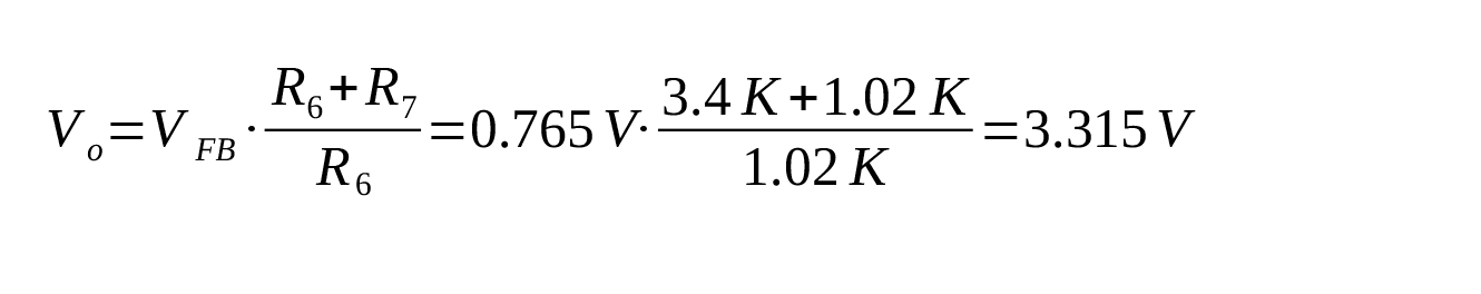
so very close to 3.3 V.
The controller
To manage all the components (which, as we will see soon, are not few!) with the necessary response speed, we opted for a 32-bit controller, to be precise a PIC of the 32MX series, equipped with USB interface to facilitate programming and management via a PC.
The bootloader on it will allow us to load the software in a very simple way through the Arduino IDE or our FishIDE if you prefer. Writing the necessary software is, therefore, very simple, exactly as if it were an Arduino-compatible board.
The clock required to operate the controller is provided by a 20 MHz quartz from which, internally, both the actual clock frequency (80 MHz) and the USB subsystem frequency (48 MHz) are derived.
The driver
As the driver for the engine, we used a Texas Instruments integrated unit, the DRV8843, a close relative of the better-known DRV8825, used in many 3d printers. This, unlike the DRV8825, is not driven by the usual STEP, DIR, and ENABLE commands, but directly by PWM pulses generated by our controller (Fig. 2); this allows considerable flexibility of use, including the generation of very dense microstepping. Let’s see how a little more in detail the driver: the two windings of the stepper motor are named A and B, hence the names of their pins.
In Fig. 3 you can see the internal (simplified) diagram of a driver channel; the part is related to channel A.
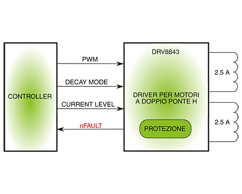
Fig. 2
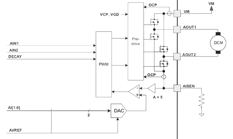
The important pins for understanding the scheme are :
–VMA is the motor power input, which can range from 8.2 to 45 Volts, hence the maximum voltage accepted by our switching power supply, equal to 46 volts;
–AIN1/AIN2 are the control inputs of the H bridge that feeds the winding. Through these pins, it is possible to control the voltage on AOUT1 and AOUT2 outputs according to Table 1.
Table 1
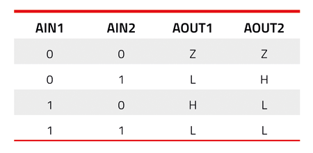
In it Z stands for ‘high impedance output,’ i.e., the equivalent of winding disconnection, L stands for the negative voltage and H for positive voltage.
The integrated unit has a control inside to avoid ‘dangerous’ conditions in the H-bridge, such as simultaneous switching on of the two upper and lower MOSFETs, which would cause a ruinous short circuit on the power supply. These 2 pins can then be used to supply power to the winding in the desired direction. Applying a logic level to the 2 pins, the winding is powered by the MAXIMUM current set, as we will see below. It is, however, possible to drive these two inputs through a PWM signal (and we will do it in our software) to supply a reduced current to the winding. When applying PWM signals, the operation is as described in Table 2.
Table 2

DECAY’ is how a winding is de-energized; we know that an inductor tends to keep the current in circulation when it is disconnected, and it takes some time to ‘discharge.’
The faster it is discharged, the faster the motor’s response to changes at the cost of more impulsive disturbances and current peaks in the system. In ‘FAST DECAY’ mode, the bridge MOSFETs are disconnected, and the winding energy flows through the protection diodes inside the MOSFETs; in ‘SLOW DECAY’ mode, the MOSFETs short circuit the winding.
As intuitive as it may seem, the faster a winding is discharged, the greater the resistance used to discharge it, so inserting the protection diodes in the discharge path reduces the time.
• DECAY is the input used to set the DECAY mode when not using the PWM. It is a 3 state-input; it should be set to LOW for a slow decay, HIGH for a fast decay, and left unconnected for a mixed decay.
• AI0 and AI1 are two inputs used to split the current in the winding; they are used as a 2-bit number, splitting the current from 100% (00) up to 0% (11) of the maximum current set via the AVREF input and the resistance on the AISEN input.
• AVREF is the reference input for setting the winding current. It can be driven via a DAC to perform microstepping or connected to a fixed reference if microstepping is performed in another way, for example, via the AIN1/AIN2 pins.
• AISEN is the resistor pin used to detect the current in the winding. The formula gives the MAXIMUM current in the winding (obtained by AI0/AI1 both at 0):

In MotorFish, we have brought all driver connections to the controller, so you can freely choose how you want to drive the motor via software.
As far as the analog inputs (AVREF) are concerned, we have exploited the fast and high-resolution PWM of the PIC combined with an external RC low pass filter to generate a wide range of motor drive currents; you can see in the diagram the R1/C8 and R2/C9 components that are the two low pass filters necessary to reconstruct the analog reference signal from the PWM output from the controller.
The magnetic encoder
Up to now, we have described a series of hardware components that could be related to any open-loop controller; here below, we describe the ‘main piece’ of the board, the magnetic encoder, able to detect the position of the motor shaft and transmit it to the controller.
As a component, we chose an AM4096 RLS, with a resolution of 12 bits (4096 steps/turn). Applied to a stepper with 200 steps/turn allows a maximum microstepping of 4096/200 = 20.48 micro steps/step. It may seem like a not very high microstepping, since on the market you can easily find controllers with 1/32, 1/64 and even 1/128 pitch, but you have to consider that :
-A denser microstepping does not necessarily correspond to higher accuracy, for the reasons we will explain shortly
– Already a 1/20 step is a precision difficult to manage by mechanics; the 3Drag, for example, has the drivers set to 1/16 step, and the mechanical settings of 64.25 micro steps/mm; a micro-step corresponds to a linear precision of 1/16.25 = 15.6 microns (thousandths of mm), well beyond the precision of the mechanics with the various games, slides, etc..
So, what are elevated microstepping for? Simply to make the motor smoother and quieter. While reducing mechanical vibrations. By increasing the micro-steps, the motor approaches a brushless motor, which moves without vibrations.
In our controller, the motor is driven by a sine wave synthesized by the PWM, which can have a high resolution at will; the motor does not behave like a real stepper but like a brushless motor.
We were saying just above that not necessarily high microstepping corresponds to an accuracy increase.
Why? Simply because of a characteristic of steppers. The positioning is given by a pair of windings, which attract or repel permanent magnets in the motor. A full step corresponds to the position of one of the poles of these permanent magnets, and therefore to a very high torque of the motor.
The maximum torque is obtained by energizing the two windings to the maximum so that the motor is positioned at the intermediate point between two poles.
If we move one full step, we are still in a maximum torque position; Fig. 3 exemplifies a full stepping operation for a single pole motor.
In microstepping, on the other hand, you position yourself at an intermediate point between the maximum torque points, providing a different current to the 2 windings. In practice, assuming a microstepping with an infinite number of steps, the current in the two windings is made up of 2 sinusoids phased 90 degrees apart.
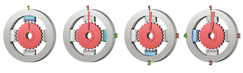
Fig. 3
Several studies have been made on this subject, not reported here for brevity, which show that the holding torque drops considerably as microsteps increase until it is overcome even by friction inside the motor itself, without even considering the mechanics of the printer.
In this case, it is possible that the motor receives 1-2-4-8-16 or more step commands without moving, and then “suddenly” jump to the required position, when the torque is sufficient to do so, frustrating the apparent greater precision given by the high number of microsteps.
As we said above, our encoder can resolve 4096 steps/revolution, which corresponds to a linear resolution on 3Drag of 12.18 microns (thousandths of a millimeter), more than enough for any purpose.
Another fact to take into consideration is the accuracy of the encoder, not to be confused with the resolution, because the resolution is a limit to the accuracy achievable by a mechanism: for example, with 4,096 physical steps, the accuracy cannot exceed 1/4,096 of revolution.
The accuracy, besides being limited by the resolution, depends on other factors, such as the linearity of the encoder, its repeatability, etc. It will, therefore, always be lower or, at the limit, equal to the resolution.
Our encoder works with an array of Hall effect sensors and a radial polarization magnet fixed on the motor shaft (as we will see later in detail). It is therefore influenced both by the linearity of the sensors and by the precision of the magnet design.
Our software is able to compensate for these non-linearities, through a calibration sketch partially, but it cannot solve all the problems mentioned above.
Let’s go back to our encoder, of which Fig. 4 shows the block diagram.

Fig. 4
The circuit consists of an array of Hall effect sensors capable of detecting the magnetic field strength at various points as an analog quantity, followed by an amplifier and a series of 3 blocks:
• Differential amplifier used to provide 2 sine waves offset by 90°, representing the encoder position in analog mode.
• 12-bit interpolator, which can derive a number between 0 and 4095 corresponding to the absolute angular position of the encoder from phased sine waves.
• 10-bit Digital/Analogue Converter, providing a variable analog output depending on the position
There are also other output blocks, able to provide various information on the position and relative movement of the motor; therefore, we have an incremental output in quadrature, similar to that present in the usual mechanical encoders (Fig. 5). Note that CPR stands for Counts Per Revolutions or impulses per revolution.

Fig. 5
The Ri output is the full turn signal. To read this type of signals, there are numerous libraries, often used for mechanical encoders.
We then have an SSI format output that returns the absolute position of the encoder in digital format (Fig. 6).
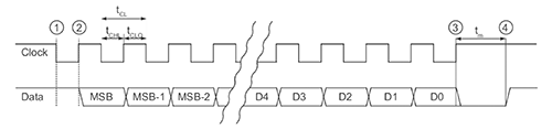
Fig. 6
This output provides a binary number up to 12 bits long (depending on the chosen resolution) in a serial format with the corresponding clock; it can be read via the SPI interface or via software.
Then we have a three-stage UVW type output, not used in our design, and a linear sawtooth output, also not of interest to us (of this, you can choose the period from 1 tooth/turn up to 8 teeth/turn. Even the tachometer output, to detect the rotation speed, is not managed in our project.
Finally, we find four sinusoidal analog outputs, mainly intended for testing, which are the direct outputs of the Hall effect sensor array (Fig. 7).
As you can see, the encoder has a considerable number of features, all of which are programmable via a series of registers accessible via the I²C interface.
We will see shortly, in the software section, how to manage this encoder through our controller.
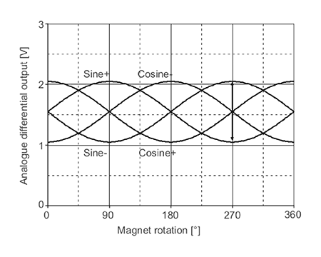
Fig. 7
The connection
MotorFish has two terminal blocks, one 4-pole for the two motor windings and one bipolar for the power supply. The motor connection is represented by the letters A+/A- and B+/B-; they correspond to the first and second motor winding. Polarity is important, although it is virtually impossible to determine the correct polarity without testing.
Then measure with an Ohmmeter the motor wires to identify each torque (the wires of the same winding have almost no resistance between them) and connect them to the connector, regardless of polarity (+ or -). When you run the test with the MotorFishClosedLoop sketch if you notice that the motor instead of stopping at one point starts to run wildly reverse one torque, e.g., swap the wires on A+ and A-.
Unlike a normal stepper, in ours, it is not possible to exchange the wires to reverse the direction of the motor, since the direction of the Encoder is prefixed and must correspond with that of the motor itself. Since sometimes it is necessary to exchange the direction of rotation; for example, it happens in the 3Drag having to overturn one of the motors for space reasons. We provided a variable in the sketch to manage it.
A voltage between about 8.5 and 45 V must be applied to the power supply connector; the higher, the better, as there will be less current absorption (the operation is switching!) and, at the same time, better motor performance.
In the 3Drag, however, we used the standard 15-volt voltage, and everything works perfectly.
Attention to polarity, clearly indicated on the PCB. Reversing it does not “explode” anything anyway, we have provided on the board a protection diode against polarity reversals.
Let’s now move on to the connector that carries the control signals; since the inscriptions are on the bottom side of the PCB, for space reasons, we show the view from below in Fig. 8. Remember that when you make the connections!
As you can see, MotorFish has a good set of interfaces, which can be managed through the software, so you can control it, in addition to the USB interface, through an I2C port or an SPI port.

Fig. 8
It also has the classic ON/DIR/STEP inputs typical of traditional controllers, making it possible to replace them with MotorFish directly .h.
• SS, SCK, SDO, and SDI are the pins related to the SPI interface.
• SDA and SCL are the pins related to the I2C interface.
• STEP, DIR, and ON are the pins related to the traditional stepper interface.
• LOCKED is a “docking” output that indicates when the motor has reached the selected position; it can be used as an error signal or to communicate any problems to the printer software.
It must be said, however, that ALL available I/Os are programmable by software, so nothing prevents you from using them for anything else. MotorFish is programmed exactly like an Arduino (or, more precisely, like a Fishino32), with all the possibilities of the case. It remains to be seen, last but not least, the connector provided for the bootloader loading, i.e., the ISP signed connector; the latter has been provided to be used directly with a PIC programmer, for example, the PicKit3, in combination with Microchip’s MPLAB IDE software. The PGC and PGD outputs can still be used as two additional I/Os when the bootloader does not need to be reloaded on the board. If you buy the MotorFish already mounted, the bootloader will still be preloaded, and then you can use the board with the Arduino IDE directly, programming it via USB.
Conclusion
Well, for this episode, we’ll stop here; we’ll resume the discussion in the next and last one explaining the bootloader and firmware loading, as well as describing the firmware itself that allows the Motorfish to work. We will also see how to configure this powerful and versatile controller thanks to the menu accessible by connecting the serial terminal to the board.
From openstore
Controller with feedback for stepper motor
Bipolar stepper motor NEMA 17 – 1,5 A
