Let’s describe the firmware of the stepper motor feedback controller and test it on the 3D printer.
(Read the first post)
In the limits of non-retroactive stepper motor control is that in applications for the drive of machines, CNC milling machines or 3D printers, the positioning can be affected by an error that makes it not always repeatable to reach the desired positions; this happens because sometimes the stepper-motor, although it receives a command, can lose its pitch.
In the case of additive 3D printing, in prints that take hours or tens of hours, the piece may present itself with some slices that are not aligned and, therefore, defective. The solution to the problem is to reverse the motor driving it with a controller able to verify that each control determines the desired position and intervene, if necessary, to correct the pitching loss.
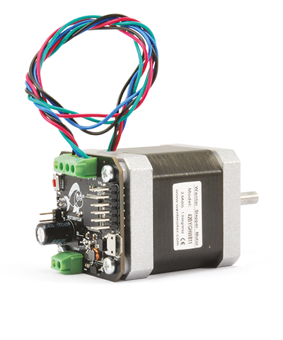
This is what happens in MotorFish, designed to read the feedback signal provided by a Hall effect magnetic encoder mounted on the motor shaft.
After having described, in the first episode, the hardware and the advantages of this controller, it’s time to move on to the programming of the board, which starts with the insertion of the bootloader; this is because MotorFish, as the name suggests, is based on Fishino architecture and is therefore programmed like an Arduino board.
Bootloader installation and firmware loading
If you have followed the articles on the Fishino32, Fishino Piranha, or Fishino Shark board, you are already well on your way! The operation is, in fact, identical, both in terms of bootloader loading and sketches. For the sake of brevity, here we will make a summary and point out the differences between the sheets; for the rest, we refer you to the corresponding articles.
So, open the IDE and start by adding the ‘Fishino’ package to the IDE via the Settings menu; after that, all the Fishino series tabs will appear in the list of tabs, including MotorFish. Of course, this will happen if you add the most recent package or at least update it to last month.
If you have mounted the board yourself, you need to load the bootloader; it is located in a folder inside the arduino15 folder of the IDE (search, the location changes depending on the operating system!). The name of the bootloader is MotorFish.hex.
Follow the instructions already used for the 32-bit Fishino for loading; you will still need to get a PicKit3 or make a handmade PIC programmer, as explained in the above articles.
Once the bootloader is loaded, to load your sketches, just press the Reset button and keep it pressed for a few seconds until a led on the board starts flashing.
At this point, you can proceed as usual for all Arduino boards.
The Firmware
For our driver, we have prepared a specific library called MotorFish, able to manage all the elements on the board.
The library contains two distinct modules, called Stepper and Encoder, as well as a file containing tables of sinuses and cosines for the generation of currents in the motor windings; these tables have been created to perform a microstepping at 64 steps per step.
Let’s start with an example that does not use the library, the MotorFishFullStepTest, to get familiar with the hardware; in this example, we perform “manually” the stepping of the engine, in full-step mode, directly driving the driver.
To understand its operation, it is essential to refer to the section dedicated, in the first episode, to the DRV8843 driver; in this example, the encoder is not used.
The sketch that you find in Listing 1 feeds the two windings alternatively through the xIN1 and xIN2 inputs, first in one direction and then in the other, according to the scheme in Fig. 1: it is the so-called “wave drive“, in practice not used because it provides a smaller torque than the simultaneous activation of two windings, as in the scheme in Fig. 2, called “full step drive“.
Listing 1
#define DEBUG_LEVEL_INFO
#include <FishinoDebug.h>
#include <FishinoFlash.h>
//////////////////////////////////////////////////////////////////
// Controller Connections -> Drivers //
//////////////////////////////////////////////////////////////////
// First winding
const int AVREF = 17; // PWM voltage reference
const int AIN1 = 18; // control input 1
const int AIN2 = 19; // control input 2
const int AI0 = 20; // current fractionation input 1
const int AI1 = 21; // current fractionation input 2
// Second winding
const int BVREF = 22; // PWM voltage reference
const int BIN1 = 23; // control input 1
const int BIN2 = 24; // control input 2
const int BI0 = 25; // current fractionation input 1
const int BI1 = 26; // current fractionation input 2
// Control I/O
const int NRESET = 27; // reset input (active low)
const int NSLEEP = 28; // sleep input (low active)
const int NFAULT = 29; // error output (active low)
const int DECAY = 30; // DECAY mode selection input (3 states)
const double RSense = 0.20; // resistance value for current measurement (ohm)
void setup()
{
// initializes the serial and waits for its opening
Serial.begin(115200);
while(!Serial)
 ;
// sets PWM frequency and resolution
analogWriteFrequency(200000);
analogWriteResolution(16);
// calculates the pwm value based on the maximum current expected in the winding
// 5.0 is a driver constant, 3.3V is the maximum output voltage from the PWM
double c = 1.0; // maximum expected current
double ARef = 5.0 * RSense * c / 3.3; // voltage value to apply on ARef
uint16_t _pwmWindingCurrent = (uint16_t)(ARef * 65535);
// sets the reference voltage for the required current
pinMode(AVREF, OUTPUT);
pinMode(BVREF, OUTPUT);
analogWrite(AVREF, _pwmWindingCurrent);
analogWrite(BVREF, _pwmWindingCurrent);
// sets the current fractionation to 100% for both windings
pinMode(AI0, OUTPUT);
digitalWrite(AI0, 0);
pinMode(AI1, OUTPUT);
digitalWrite(AI1, 0);
pinMode(BI0, OUTPUT);
digitalWrite(BI0, 0);
pinMode(BI1, OUTPUT);
digitalWrite(BI1, 0);
// de-energises both windings
pinMode(AIN1, OUTPUT);
digitalWrite(AIN1, 0);
pinMode(AIN2, OUTPUT);
digitalWrite(AIN2, 0);
pinMode(BIN1, OUTPUT);
digitalWrite(BIN1, 0);
pinMode(BIN2, OUTPUT);
digitalWrite(BIN2, 0);
// disables the SLEEP mode
pinMode(NSLEEP, OUTPUT);
digitalWrite(NSLEEP, HIGH);
// releases the driver reset, enabling it
pinMode(NRESET, OUTPUT);
digitalWrite(NRESET, HIGH);
// sets the error I/O to input, so that it can detect
// possible errors in the driver
pinMode(NFAULT, INPUT_PULLUP);
}
// 10 milliseconds between each motor phase
// to vary the speed you need to modify this number
const int del = 10;
void loop()
{
// cycles between the 4 phases of the windings
Serial << “Fase 1\n”;
digitalWrite(AIN1, 1);
digitalWrite(AIN2, 0);
digitalWrite(BIN1, 0);
digitalWrite(BIN2, 0);
delay(del);
Serial << “Fase 2\n”;
digitalWrite(AIN1, 0);
digitalWrite(AIN2, 0);
digitalWrite(BIN1, 1);
digitalWrite(BIN2, 0);
delay(del);
Serial << “Fase 3\n”;
digitalWrite(AIN1, 0);
digitalWrite(AIN2, 1);
digitalWrite(BIN1, 0);
digitalWrite(BIN2, 0);
delay(del);
Serial << “Fase 4\n”;
digitalWrite(AIN1, 0);
digitalWrite(AIN2, 0);
digitalWrite(BIN1, 0);
digitalWrite(BIN2, 1);
delay(del);
}
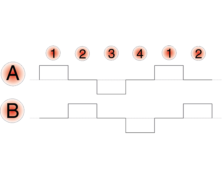
Fig. 1
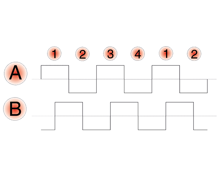
Fig. 2
In the latter case, two windings are always energized, while the motor is positioned in the midpoint between the two poles, thus providing higher torque. We leave you the experimentation of this mode, which is not the subject of the article, since we are interested in microstepping, to achieve which, instead, it is not enough to activate the windings in sequence. Still, it is necessary to vary the current in them, and this is what the library provided does where, through a PWM with rather high frequency and 16-bit resolution, the current is continuously varied by acting on the AREF and BREF inputs. The current must vary in a sinusoidal way, with the sinusoids out of phase 90 degrees between one winding and the other, as in Fig. 3; in this scheme, the sinusoids have been deliberately left continuous, that is not discretized; the number of “microsteps” depends on how finely the sinusoids are subdivided, which, working digitally, will be forcedly stepped. If the current varies continuously, the operation of a brushless motor with infinite microstepping is achieved.

Fig. 3
The library provided uses a table containing 64 values for the sine and cosine, brought back to a 16-bit integer number, while the system “brushes” through this sequence of values recreating the two waveforms; to advance by one micro-step it is sufficient to move in the table and take the corresponding current values. In Listing 2, we report one of the tables as an example.
Listing 2
const uint16_t cosineTable[] = {
65535, 65515, 65456, 65357, 65219, 65042, 64825, 64570, 64275, 63942, 63570, 63161, 62713, 62227, 61704, 61143,
60546, 59912, 59242, 58537, 57796, 57021, 56211, 55367, 54490, 53580, 52638, 51664, 50659, 49623, 48558, 47463,
46340, 45189, 44010, 42805, 41574, 40319, 39039, 37735, 36409, 35061, 33691, 32302, 30892, 29465, 28019, 26557,
25079, 23585, 22078, 20557, 19023, 17479, 15923, 14358, 12785, 11203, 9615, 8022, 6423, 4821, 3215, 1608,
 0, 1608, 3215, 4821, 6423, 8022, 9615, 11203, 12785, 14358, 15923, 17479, 19023, 20557, 22078, 23585,
25079, 26557, 28019, 29465, 30892, 32302, 33691, 35061, 36409, 37735, 39039, 40319, 41574, 42805, 44010, 45189,
46340, 47463, 48558, 49623, 50659, 51664, 52638, 53580, 54490, 55367, 56211, 57021, 57796, 58537, 59242, 59912,
60546, 61143, 61704, 62227, 62713, 63161, 63570, 63942, 64275, 64570, 64825, 65042, 65219, 65357, 65456, 65515,
};
Once the library is available, microstepping becomes very easy:
#includes < FishinoFlash. h>
#includes < MotorFish. h>
void setup()
{
Stepper. setWindingCurrent(1.0);
Stepper. energize(true);
delay(100);
}
void loop()
{
Stepper. stepForward();
delayMicroseconds(100);
}
As you can see, in setup(), we start with setting the maximum current in the windings (1 ampere) and energize the motor. In the loop(), we perform a step (actually, a micro-step) every 100 microseconds. If we load the sketch, we’ll see the motor rotate at a constant speed. By changing the value in the delayMicroseconds(), we can vary the rotation speed.
Let’s now quickly see how the encoder only works; here too, we have prepared a library (the Encoder.cpp file contained in the MotorFish library) that deals with low-level electronics, making life much easier.
In the example, in Listing 3, we use only the encoder and print on the serial port the position of the motor shaft, which can be seen by turning it by hand. In this sketch, we use the SSI interface to read the absolute position of the encoder; in setup(), we initialize the encoder itself and check that the magnetino is in the correct position. This is crucial, as accuracy depends very much on the correct positioning of the magnet concerning the encoder chip. In the loop, afterward, we read the position from the encoder and, if different from the last read, we print it on the serial port.
You can try the operation by launching the sketch, opening the serial port and manually rotating the motor shaft.
Listing 3
#include <FishinoFlash.h>
#define DEBUG_LEVEL_INFO
#include <FishinoDebug.h>
#include <MotorFish.h>
int32_t oldPos = 0, curPos = 1;
void setup()
{
Serial.begin(115200);
while(!Serial)
 ;
DEBUG_INFO(“MotorFish Encoder Test\n”);
Encoder.resetMotorPos();
delay(100);
// performs a magnet check
if(Encoder.isMagnetTooFar())
 DEBUG_ERROR(“Il magnete è troppo lontano\n”);
else if(Encoder.isMagnetTooClose())
 DEBUG_ERROR(“Il magnete è troppo vicino\n”);
else
 DEBUG_INFO(“La posizione del magnete è OK\n”);
}
uint16_t ssi = 0, prevssi = 1;
void loop()
{
// reads the position using the SSI interface
ssi = Encoder.readSSIPosition();
// prints the position only if the motor has moved
if(ssi != prevssi)
{
 DEBUG_INFO(“SSI:%6u\n”, ssi);
 prevssi = ssi;
}
delayMicroseconds(100);
}
So far, we have used the driver and encoder separately, but since we want to create a closed-loop system, it is time to merge them!
This may seem simple, but it’s not! The main problem with closed-loop systems is that, if not properly designed, they tend to be very unstable or slowly reach the equilibrium point. In the first case, the engine oscillates around the required position, often quite violently, without ever stabilizing. In the second case, the response is so slow that it is unusable.
In our case, we implemented a simple but effective PID (Proportional-Integral-Derivative) system. PID systems are often used in closed-loop controls because they allow a relative simplicity of implementation and, at the same time, a good control. They are not the only systems that can be used, but other methods are outside the scope of this Article. To explain how it works, we make a thermal analogy, assuming we have to bring a resistor (e.g., the printer plate, or the printer head) to a set temperature.
The ON-OFF system
The first thing that comes to mind is to put a thermistor on the platter, connect it to a dial gauge, and compare the voltage supplied by the thermistor with a reference voltage. If it is lower than required, the resistor is powered, if it is higher, it is switched off.
If you have tried to do so, you will have noticed that the temperature never stabilizes at the required point, but continues to fluctuate between a higher and a lower value; this is because the platter and the resistor itself have a not indifferent thermal inertia, and respond late to current variations.
When the thermistor has reached the required temperature, for example, it is possible that even when the power supply is disconnected, the heat may still flow from the heating element to the platter for some time, causing the temperature to exceed. Similarly, if we cut the power and when the temperature on the thermistor has dropped to the required value, restoring the power supply will continue to drop for some time before it starts to rise again.
If for a heating plate, the problem is relative, already for the print head, it becomes relevant; if we talk about the positioning of the motors, the problem becomes huge; in fact, we cannot have the printer plate flickering around the required point!
The one seen so far is an ON-OFF type control, the most crude you can use. If the position of the engine is “minor” than that required, I make it go forward at full force. If it is “major,” I make it go backward.
The Proportional System
Wanting to be a bit more refined, we introduce a proportionality between the position error (or temperature error, in the case of the heated dish/head) and the required one. The further away we are from the desired point, the more current (or speed) we give; as we get closer, we reduce the power supplied until we cancel it once we reach our destination. This is the Proportional method (the P of PID! ). It would seem an excellent method, and it would be if there was no inertia, which can be either thermal (in the case of the heated plate) or mechanical (in the case of the head/plate movement of the printer). Also, canceling the current once you reach your destination means that it will never be reached. We will approach (in the absence of inertia) infinitely, without ever reaching it. And the closer we get, the slower we will move forward: it is the classic asymptotic behavior of purely proportional systems. Also, even when we reach the position, the system will be very sensitive to external disturbances, since, in that position, the energy we apply to it is zero. This is not good!
The PID system
We have seen that the Proportional system acts according to the error between the required and current position. It does not take into account the “history” of position variation in any way. Whether we are approaching the desired position quickly or slowly is irrelevant, the only thing considered is the difference between the current and the final.
In the case of the engine, it’s easy to guess that if we were going fast, the mechanical inertia would tend to overtake the required position even if we cut the power at the right moment, while if we go slow, it may take too long to reach it.
Here intervenes the D part of the PID, the Derivative, which in Italian can be translated into Differential.
This factor takes into account the speed with which the error decreases over time: if we are approaching quickly, the decrease is rapid, and therefore we know we have to “brake earlier.” By inserting this parameter, we can almost totally compensate for the problems due to the mechanical inertia of the platter.
The Integral part of the system is a bit more complex to explain; it takes into account the sum of the errors over time and is able, for example, to solve the problem of canceling the current when the required position is reached. Making a quick (and incomplete) example, if the motor reaches the required position, without the integral component, the current goes to zero. At the same time, with the integral component, the system “remembers” how much effort it has made to reach it and will compensate by increasing the current.
At this point, we see how to put the three systems together; in theory, it is enough:
-store the current position error (part P);
-store the difference between the current error and the previous one (part D);
-maintain a sum of errors as we go along (part I);
-put the resulting numbers into a specially calibrated formula that returns the current value to be applied to the motors.
In practice, we still have to deal with some practical problems:
-we have to (almost necessarily…) work with whole numbers, because the floats are too slow;
-we are obliged to give a limit to the measured values since we cannot let an infinite current flow into the motor;
-in an Integral part it is useless, indeed, harmful, to memorize a history of errors too “old”;
-the formula itself is simple, but the determination of its parameters is not.
Simply put, we could write the formula in this way:
Current = Cp – p + Cd – d + Ci – i
Where Cp, Cd, and There are 3 constants to determine, p is the position error, d is its variation over time, i is the “sum” of the errors over time.
The determination of the 3 constants is not a trivial operation, nor is the management of the full part of the errors.
For constants, there are more or less empirical methods (which we have not applied!), while the second part depends very much on the size of the integers in the controller, the type of device controlled, etc..
In practice, this is the classic example where experimentation carries a lot of weight!
To make it easier to understand, we have separated the sketch into two parts; the first, extending the library with the ClosedLoop class, and the second containing the PID algorithm, update handling, etc.
The second one, which is the actual program, deals with the high-level management of the engine and its settings; it is called MotorFishFirmware, and you can find it among the examples of the MotorFish library.
In practice, just load it on the board, connect it to the engine and PC via a serial interface and follow the menu that will appear on the serial monitor to change all the parameters without having to recompile anything.
The firmware is managed through a textual menu structure. It allows both to finely adjust the operating variables (PID, motor current, etc…) and to modify the direction of rotation of the stepper and/or the encoder positioning (in front or behind the motor) and, last but not least, to perform calibration and a series of function tests.
Firmware configuration and loading
The firmware is already ready to load, and in theory, no changes are required.
In practice, we wanted to leave open the possibility of modifying the serial port to connect to for settings.
Basically, as can be seen from the code section below, the interface is Serial, corresponding to the USB interface:
// select which serial port to use
// Serial is USB port
// Serial0 is Serial connected to SDI/SDO
#define MOTORFISH_SERIAL Serial
Why change it? Simply to avoid a possible “bad experience” had by the author during the test carried out on the 3Drag printer! In fact, in the 3Drag, the space is limited, and the position of the MotorFish board is very close to the printer plate. The plate, moving around, can cut the USB connector, if connected to the cable. The writer happened to load the sketch, forget to invert the direction of the motor, launch the calibration function, and see the printer plate cut the USB connector on the board, ruining it irreparably.
To avoid this problem, we have left the possibility to use a second serial port, for which, however, an external USB/Serial converter is needed, connected to the SDI/RX and SDO/TX pins. These pins are simple DuPont connectors, perpendicular to the board itself, so they do not interfere with the mechanics. The activation of the second serial is obtained by replacing Serial with Serial0 in the section shown above:
// select which serial port to use
// Serial is USB port
// Serial0 is Serial connected to SDI/SDO
#define MOTORFISH_SERIAL Serial0
Firmware Management
Once the board is connected to the PC (for the moment the presence of the motor and the external power supply is irrelevant), it is enough to open a serial monitor and then press a button, possibly space. The following menu will appear on the serial monitor:
MotorFish – MAIN MENU
1) Change running mode (DISABLED,STEPPER,*CLOSED LOOP*)
2) Change encoder placement (*REAR*,FRONT)
3) Change motor positive direction (*CLOCKWISE*,COUNTERCLOCKWISE)
4) Enter calibration menu
5) Enter PID menu
6) Enter test menu
Select function:
This is the main screen and provides access to all the various functions.
The commands are given using the numeric keys (in this case from 1 to 6), and the related items are described below.
Point 1
Here we can change the operating mode of the engine by choosing between:
-DISABLED engine deactivated;
-STEPPER operation in stepper mode (the encoder is not used);
-CLOSED-LOOP operation in servo mode with encoder.
The first is useful for testing a connected machine without risking the motor “starting” on its own while you are working; the second mode deactivates the encoder and transforms the system into a simple driver with 64-step microstepping. The last mode is the one we are interested in, i.e., the retroactive operation with the encoder. Pressing the 1 button repeatedly will switch from one mode to another, which will be highlighted by the two asterisks surrounding the active one (DISABLED, STEPPER, CLOSED LOOP).
Point 2
Here we have the possibility to modify the positioning of the encoder on the motor itself; this should be positioned for convenience ON THE BACK of the motor, gluing the magnet directly to the shaft. In some cases, due to lack of physical space (as it happens for the Y-axis on the 3DRAG), it is necessary to move the encoder in the FRONT part of the motor; in this way, however, the direction of rotation is reversed and, therefore, it is necessary to inform the firmware of the thing.
Point 3
As with the encoder position, it is sometimes necessary to reverse the direction of rotation of the motor. Always taking 3DRAG as an example, in this case, to make the change, we had to turn the X-axis motor and then reverse the direction of rotation. If in a normal stepper, to do this it is sufficient to exchange the polarity of the cables of one of the two windings, in the case of MotorFish this is NOT possible, as the system must be synchronized with the encoder. We have therefore provided the possibility of reversing the direction via software between CLOCKWISE and ANTI-CLOCKWISE.
Point 4
The calibration submenu can be accessed via point 4:
MotorFish – CALIBRATION MENU
1) Run calibration (READ MANUAL FIRST!)
2) Dump calibration values
9) Erase calibration date
0) Return to the main menu
Select function:
Here we have three points (besides the 0 to return to the main menu); through the first (1), the calibration cycle is executed, through the second (2) the calibration values are printed, and through the third (9) all calibration data are deleted.
The calibration consists in making a complete rotation of the motor, step by step, comparing the theoretical values of the position (those obtained by counting the steps, for example!) with those detected by the encoder, and building a correction table to be stored in the EEPROM of the board.
These values will then be used during the operation to correct the encoder readings and provide greater accuracy.
The magnetic encoder has, in fact, a RESOLUTION of 12 bits (4096 points) per revolution, something not to be confused with PRECISION, as said at the beginning of the article. As stated in the menu, care must be taken before starting the calibration procedure; it moves the motor (in the positive direction) by a minimum of one complete rotation up to a maximum of two. It is, therefore, necessary to ensure, before giving the command, that the mechanics can perform this movement without damage. In the case of the 3Drag, the printing plate must be moved close to zero so that it can move freely forward.
Once the command is launched, the stepper will start moving, first searching for the position of the physical zero (the one corresponding to the encoder zero point) and then performing a complete rotation by reading the positions with the encoder at the same time. At the end of the procedure, the minimum and maximum errors detected will be printed, and the correction table will be created in the EEPROM.
It is possible to repeat the calibration procedure several times, although the values used by MotorFish will only be those of the last run.
At the risk of sounding repetitive, we recommend that you pay attention by activating any movement to the USB connector connected to the board. Then use a mechanical stop or the second USB interface, as explained on the previous pages, which does not involve these risks.
Point 5
Through this point, you enter the PID submenu, which allows you to modify the feedback parameters of our board:
MotorFish – PID MENU
1) Change motor current (2.50)
2) Change Kp value (20000)
3) Change Ki value (0)
4) Change Kd value (0)
5) Change integral damping factor (32200)
0) Return to the main menu
Select function:
Here we can modify the maximum current in the motor (point 1, from 0 to 2.5 ampere), the 3 values of the constants of the PID algorithm (Kp = proportional, Ki=integral and Kd=derivative), between -32767 and 32767 and, lastly, the value of “attenuation of the integral component,” from 0 to 32767.
The latter serves to avoid that the Ki coefficient influences the “too old” history of the engine position. In practice, a damping coefficient of 32767 uses the entire history of the engine using the Ki coefficient; by reducing the damping factor, the past history after a few cycles is “forgotten.”
The proposed value, 32,200, is sufficient to avoid the influence of values that are too old.
The 3 values, as mentioned at the beginning of the article, are rather experimental. The most important value is the Kp, that is the proportional value, which should usually be kept above 5,000 (20,000 in our case, but tested!). Too high a coefficient will lead to instability (the mechanics will start to vibrate close to the equilibrium point without reaching it, too low a value will not be sufficient to compensate masses and friction, providing poor precision).
The Ki coefficient (together with the damping factor) manages the “error history” of the engine and allows to correct positions very close to the final one. The low value should be used, usually between 5 and 50, maximum 100. Too large a value will lead to great instability and vibrations around the equilibrium point. The Kd coefficient manages the “speed of reaching the equilibrium point.” In our case, it has very little impact, since the equilibrium point is reached very quickly. In our tests, it was practically irrelevant.
Point 6
You can access the test menu via this point :
MotorFish – MENU TEST
1) Encoder test
2) Open-loop stepper test
3) Closed-loop stepper test
4) Speed/acceleration test
0) Return to the main menu
Select function:
Through 1), we can access the encoder test only; selecting it, the motor position will be printed on the serial monitor; by manually rotating the pin, you will see the numbers change.
The position is not limited to a single lap but includes multiple rotations, both in one direction and the opposite. The position is represented by a 32-bit integer, with values from +/-2147483648, corresponding to +/- 167772 full engine revolutions, which is more than sufficient for any practical application.
2) performs a spin test without feedback, then in normal stepper operation; one spin forward, then one backward, and so on until a key is pressed.
The positions detected by the encoder are printed on the serial monitor.
By carrying out this test, you will see that the current absorbed by the motor is high and depends on the current set in the PID menu. Operation in stepper mode requires the application of maximum current to the motor regardless of the effort it is subjected to.
Therefore, be careful not to exceed the permissible value for your motor, in order not to damage it; the driver can provide 2.5 amps per winding. An interesting test to perform is to lock the crankshaft manually. You will feel the engine strain, jump and lose steps, as always happens to stepper motors when they are blocked. Lost steps are not recovered when the block is removed.
3) performs a test in servo mode, i.e., using the encoder. The test is practically identical to that of point 2, with the two differences in the behavior described below.
-The current absorption will be drastically lower: the motor absorbs the necessary amount to maintain the required position. If it is not subjected to stress, absorption approaches zero. You will notice this, especially if you apply it to the 3d printer; the motors will always be cold, even if you set the current to the maximum.
-When you manually lock the shaft, you will notice that the current consumption will increase strongly, and the motor will try very hard to reach the required position. Once the blockage is removed, the engine will “run” to the correct position without losing steps.
In the case of the printer, if the engine, during operation, is momentarily blocked by an obstacle (e.g., a lump of plastic banging against the head), the print will not be ruined, and you will not find “half a print” translated, but only an imperceptible local error.
The 4) is the most “dangerous” test of the series; the motor performs a complete lap in a positive direction (clockwise or counter-clockwise depending on the setting in the main menu) at maximum speed, which will be measured at the same time and printed on the serial monitor.
The number resulting from this test should not be considered as the speed reached by your mechanics but as a limit value.
To give an example, on our 3Drag comes an equivalent value of about 500 mm/second of plate displacement, which is a disproportionate value; however, it can give you an indication of how much you can enter as maximum in the configuration parameters of the printer, for example, a value around 30%-50% of what is detected, or 170-250 mm/second in this case.
Conclusion
Well, with this we have finished the description of the firmware and the test of the stepper motor feedback controller to be performed after the bootloader installation and firmware loading; soon we will publish an article where we will explain how to install MotorFish on the stepper motors of the 3Drag printer, which we mentioned in the previous pages.
From openstore
Controller with feedback for stepper motor
Bipolar stepper motor NEMA 17 – 1,5 A
