Is a storm on its way? Let’s find out using a circuit based on a sensor to detect electrical shock in the atmosphere capable of letting us know how near and how strong it is.
Meteorological centers can monitor, besides atmospheric parameters in order to estimate rain probability and volume, also storms and their related electrostatic phenomena, such as lightnings. In some countries exposed to consistent electrical atmospheric phenomena in their risks, this becomes particularly important. Without making any reference to the word of cinema, where catastrophic movies with “killer” lightnings are not lacking, we can understand how lightnings we see crossing the sky and hitting the ground could be dangerous, due to the huge amount of energy they can transmit eet coming from the sky (where they are formed) and crashing to the ground, on buildings, trees and unfortunately even on humans. Such danger is even higher in those areas where lightnings can form even in the near absence of storms, out of the blue. Without taking into consideration damages caused by lightnings happening near networks of power distribution and telecommunication grid to electric and especially electronic devices, in form of induced overvoltage.
The analysis of atmospheric electric phenomena is carried out using various methods (the oldest one being Benjamin Franklin’s kite) based on preemptive evaluation of static electricity buildups in atmosphere and on locating electric discharges, using complex and pricey apparatuses, however this can also be done on an amateur level, in your home, thanks to devices such as a sensor based on the AS3935 IC by AMS, which is employed in the application described in the next pages. The component used can detect radio electric disturbances caused by electric arcs (such as lightnings) and, through a specific processing, can provide a signal corresponding to the detection of a lightning and its intensity.
A bit of theory
Lightnings are atmospheric electric discharges of the air – air or air-ground variety triggered by the buildup of a consistent electric charge, that is when a strong electric potential differential is created between two points in the atmosphere or between air and ground (but also between air and sea or watercourses); when the electric potential difference is such to overcome the dielectric resistance of the medium between the two points (usually it’s air, which can be more or less humid…) The electric arc is triggered, i.e. the lightning, so a flux of current crossing an isolating medium.
The light is caused by the ionization of gas component in the air comprised between the points of the arc, that is the electrons forcibly separated by the very strong electric field during discharge return to their atomic bonds; the energy returned by the election before reentering its bond produces a photon, which is a light particle, which in the lightnings is for the most part within the visible spectrum.
This electrical activity can be perceived from a distance just like a radioelectric signal transmitted by an emitter: Hertz demonstrated it in his experiment, by triggering some sparks and detecting the weak voltage resulting from a distance using a dipole. In fact, we can think of a lightning as an oscillation electrically stimulating and propagating an electrical charge to a distance dependent on the composition of air and its conditions, as well as the performances of the receiving antenna and the device used for reception.
By using a sensible RF receiver and processing the signal received using a proprietary algorithm, the AS3935 integrated can determine if the electrical activity detected is caused by lightning, and it estimates the probable distance based on the signal’s intensity; with distance we mean distance from the start of the storm where lightning start to form and the chip can determine it with sufficient approximation between a maximum of 40 km and a minimum of 1 km. The algorithm is used to tell apart, with a certain approximation, lightnings (atmospheric discharges) and electrical discharges produced for instance by ignition coils and spark plugs, brush electric motors, and microwave ovens.
The lightning detector
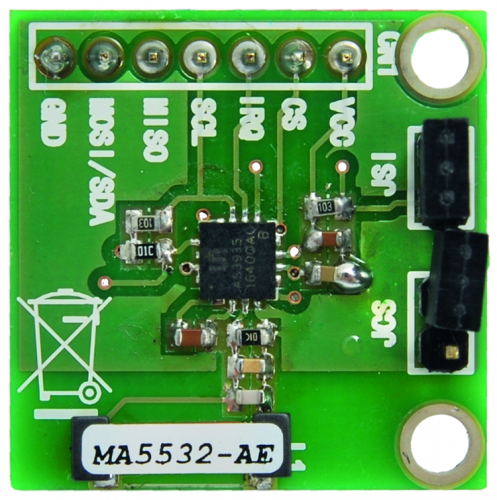
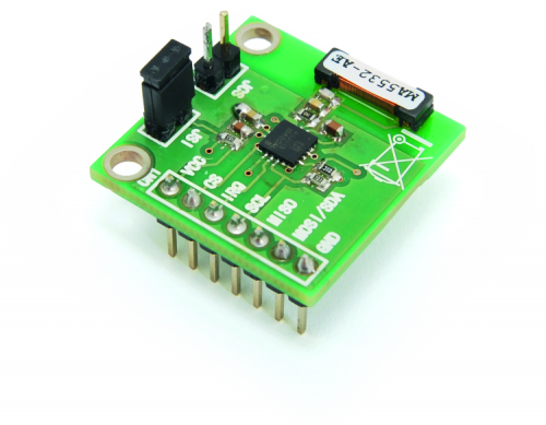
In order to make the atmospheric discharges sensor more easily usable, we have made a breakout board containing the AS3935 integrated supply, you can find its electrical diagram in these pages. The heart is clearly the IC, and we bring its power, the communication bus with external microcontroller circuits and the major control signals, to the outside. All the lines to connect externally or to be handled externally are brought to a line of pads with 2.54 mm gap on one side, to which we can apply a pinstrip. Data connection with the external world is serial, using an I²C-Bus or SPI bus; in the last case we will make use of the lines:
- MISO (Master Input Slave Output) which is to breakout boards output used to send data related to detected lightnings to Arduino;
- MOSI (Master Output Slave Input) which is the data output of Arduino used to communicate setting message or confirmation message to the breakout board;
- CS (Chip Select) which is the line of Arduino enabling the breakout board to interact on the SPI bus; CS is useful because several devices can use the SPI and in order to avoid data collegians we need every communication session to enable just one device per time.
- SCL (clock) corresponding to the signal synchronizing bus communication.
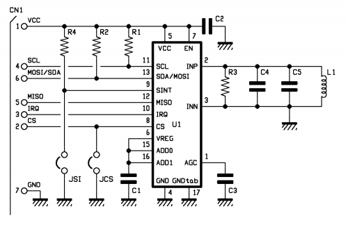
The signals above are brought to the CN1; for the SCL clock line in the MOSI we have inserted pull-up resistors.
Note that pin 8 of the AS3935, i.e. the CS is kept at logic level high from its internal pull-up resistor if not specified otherwise, but it can be forced to logic zero by the JCS jumper where external management is not needed.
For what concerns serial communication mode, this can be selected on the breakout board using the second jumper, labeled SI, intervening on pin 9 (Select Interface); the integrated AS3935 integrated works:
- in SPI mode if being at 9 is at logic zero;
- in I²C mode if Select Interface is at VDD.
In our application we chose the first option, so you can see the jumper has been closed.
We then have pin IRQ (10), brought to terminal 3 of the CN1 connector, which communicates the microcontroller when IRQ is an output that AS3935 Brinks logic level high when a lightning is detected and the corresponding value is written in one of the internal registers (REG0x03[3:0]).
Let’s continue with the analysis of the circuit diagram and move on to the input stage, which is the stage that allows us to detect the radioelectric disturbance corresponding to the lightning; this is related to pins 2 and 3, which are the radio-receiver input of the integrated circuit, which requires an anti-resonant circuit to the input in order to tune a certain bandwidth and exclude low-frequency disturbances which are not relevant to the purpose.
The tuning circuit is composed of a coil (AF inductance) that can be purchased ready-made into parallel mounted capacitors, ensuring the capacity value required to determine the desired frequency at center bandwidth. The coil also acts as receiving antenna and ensures an optimal sensibility. R3 resistor, which is in parallel to the anti-resonant circuit, worsen the quality factor but at the same time limits amplitude of the signal introduced in the tuning stage on the other hand; by worsening the quality factor we widen the bandwidth that can be tuned, which is fine because we have to detect electrical discharges that have no precise frequency, but can fall within a wide spectrum.
The center bandwidth frequency of the tuning stage is determined by the formula:
f = 1/6,28 x LC
Where L is the coil’s inductance and C is the sum of C4 and e C5. Quality factor Q is provided by the formula,:
Q = f/Bw
Where Bw is the bandwidth of the antiresonant circuit.
The radio receiver is a direct amplification region receiver and is equipped with AGC, to adjust gain in a base of the expected level on the output; C3 capacitor determines the intervention time of the AGC.
The signal provided is then analyzed by the dedicated block within the chip, which compares it with the background noise average and, using the dedicated algorithm, determines what could be a lightning and what has to be dismissed, therefore produces a data strings that are placed in a dedicated registry and, when the value corresponds to a lightning’s, it generates an impulse on the IRQ (pin 3 of CN1 connector).
Let’s conclude the analysis of the electric diagram of the detector board with pins ADD0 and ADD1, which should be used to set the address of the IC when the I²C bus is used for communication and in this case, being unused, are brought to logic level high by connecting them to the VREG output (pin 6) of the voltage regulator internal to the integrated circuit; voltage provided by that pin is filtered by the ripple through C1 capacitor.
With that said, let’s move on to see how the breakout board is used in the circuit.
Application
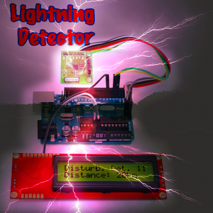
The project we are proposing is essentially made of three elements: lightning detector, available on the breakup board, an Arduino Uno or Fishino Uno board, which duty is to analyze the signal provided by the sensor, process it and show on serial LCD display (which is the third element of the circuit) the information extracted, i.e. the number of electric discharges detected that can be considered “spawn” of lightning along with estimated distance.
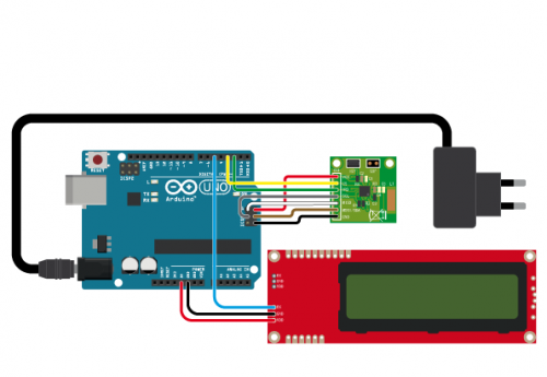
Everything must be connected as we can see in the wiring diagram visible in these pages, where the sensor breakout board interfaces with Arduino through the ISCP connector, since the latter carries the complete, 4-line SPI bus.
In order to manage the serial display, we use a software serial, emulated thanks to the SoftwareSerial.h library, which allows you to free the hardware serial for possible applications that need it. The sensor breakout board is connected, as mentioned, through an SPI bus, from which it receives all the settings and communicates data regarding lightning detection; the onboard chip is enough on itself to measure intensity and detect the course of the electrical discharges detected by the coil mounted on the breakout board, therefore the data provided to not require any special processing by Arduino.
The connection with the breakout board takes advantage of the SPI bus lines reported on the ICSP connector; then we have GND (ground) and Vcc (connected to +5V) used by the board to take power from Arduino.
CS (active at logic level 0) is handled by Arduino’s digital I/O 3, set from the sketch as output and the IRQ of the breakup board is instead interfaced with the digital I/O 2, initialized as input, since, to be specific, IRQ notifies Arduino of a possible microcontroller interfacing with the IC circuit or its breakup board capable of reading the content of the registry.
When IRQ goes back to logic zero there is a pause of at least 2 ms before the registry is read again.
For managing the sensor from Arduino and in order to read detected data, we have used a library developed by a member of the community (Raivis Rengelis) which can be downloaded by github at the web address https://github.com/raivisr/AS3935-Arduino-Library. This is handled by a sketch which code is reported in List 1.
Listing1
#include <SPI.h>
#include <AS3935.h>
#include <SoftwareSerial.h>
#define LCD_pin 5 // LCD data signal
const int NoDetect=30;
int counter;
int NumDisturber=0;
SoftwareSerial LCD = SoftwareSerial(0, LCD_pin);
void printAS3935Registers();
byte SPItransfer(byte sendByte);
void AS3935Irq();
AS3935 AS3935(SPItransfer,3,2); //change to AS3935(SPITransfer,9,3) if using slot #2
void setup()
{
serLCDInit();
backlightOn();
clearLCD();
lcdPosition(0,3);
LCD.print(“Lightining”);
lcdPosition(1,5);
LCD.print(“Sensor”);
delay(1500);
clearLCD();
Serial.begin(9600);
SPI.begin();
SPI.setDataMode(SPI_MODE1);
SPI.setClockDivider(SPI_CLOCK_DIV16);
SPI.setBitOrder(MSBFIRST);
AS3935.reset();
delay(10);
AS3935.setOutdoors();
AS3935.registerWrite(AS3935_NF_LEV,2); //write 2 in the Noise Level register
//AS3935.registerWrite(AS3935_SREJ,0); //write 2 in the Noise Level register and run calibration
// if lightning detector can not tune tank circuit to required tolerance, calibration function will return false
if(!AS3935.calibrate())
Serial.println(“Tuning out of range, check your wiring, your sensor and make sure physics laws have not changed!”);
// now we print the value in the calibration register TUN_CAP it is in the range 0 - 15
tunecap=AS3935.registerRead(AS3935_TUN_CAP); //Internal calibration
Serial.print(“Tuning cap register is “);
Serial.println(tunecap);
AS3935.enableDisturbers();
printAS3935Registers();
// AS3935IrqTriggered = 0;
}
void loop()
{
delay(1000);
Serial.println(“Waiting...”);
if (counter==0)
{
NumDisturber=0;
counter=NoDetect;
clearLCD();
lcdPosition(0,1);
LCD.print(“No lightining”);
lcdPosition(1,4);
LCD.print(“detected”);
}
else
{
counter=counter - 1;
}
}
void printAS3935Registers()
{
int noiseFloor = AS3935.getNoiseFloor();
int spikeRejection = AS3935.getSpikeRejection();
int watchdogThreshold = AS3935.getWatchdogThreshold();
Serial.print(“Noise floor is: “);
Serial.println(noiseFloor,DEC);
Serial.print(“Spike rejection is: “);
Serial.println(spikeRejection,DEC);
Serial.print(“Watchdog threshold is: “);
Serial.println(watchdogThreshold,DEC);
}
// this is implementation of SPI transfer that gets passed to AS3935
{
return SPI.transfer(sendByte);
}
void AS3935Irq()
{
int irqSource = AS3935.interruptSource();
// returned value is bitmap field, bit 0 - noise level too high, bit 2 - disturber detected, and finally bit 3 - lightning!
if (irqSource & 0b0001)
Serial.println(“Noise level too high, try adjusting noise floor”);
if (irqSource & 0b0100)
{
NumDisturber+=1;
Serial.println(“Disturber detected”);
clearLCD();
lcdPosition(0,0);
LCD.print(“Disturb. Det: “);
LCD.print(NumDisturber,DEC);
counter=NoDetect;
}
if (irqSource & 0b1000)
{
// need to find how far that lightning stroke, function returns approximate distance in kilometers,
// where value 1 represents storm in detector’s near victinity, and 63 - very distant, out of range stroke
// everything in between is just distance in kilometers
int strokeDistance = AS3935.lightningDistanceKm();
if (strokeDistance == 1)
{
Serial.println(“Storm overhead, watch out!”);
lcdPosition(1,1);
Serial.println(“Storm overhead”);
lcdPosition(1,3);
Serial.println(“WATCH OUT!”);
counter=NoDetect;
}
if (strokeDistance == 63)
{
Serial.println(“Out of range lightning detected.”);
lcdPosition(0,2);
Serial.println(“Out of range”);
lcdPosition(1,0);
Serial.println(“lightning detect”);
counter=NoDetect;
}
if (strokeDistance < 63 && strokeDistance > 1)
{
Serial.print(“Lightning detected “);
Serial.print(strokeDistance,DEC);
Serial.println(“ kilometers away.”);
lcdPosition(1,0);
LCD.print(“Distance: “);
LCD.print(strokeDistance,DEC);
LCD.print(“km”);
counter=NoDetect;
}
}
}
For what concerns the serial LCD display, this is connected to Arduino through 5V and GND terminals for power and digital I/O 5, set as output, serially sending data to the RX terminal on the LCD.
The project shows how to read data detected by the breakout board, particularly when a possible storm is detected by showing the notification on a serial LCD display.
Normally, the storm notification is displayed along with the number of detections in less than 60 seconds. If within 60 seconds, there are no other detections, then the notification “No lightning detected” is displayed .
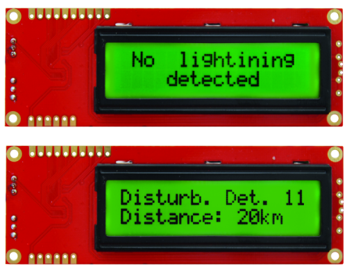
If in the integrated circuit’s registry, detection distance is available, then this piece of information is also displayed in the second line, with a message along the lines of:
Disturb Det. x
Where “x” indicates the number of discharges detected. Below, you can see :
Distance: n km
Where “n” is the estimated distance where lightning hit the ground. If a distance is lower than the minimum, the display that shows Storm overhead on the first line and WATCH OUT on the second line!
From openstore
Serial Enabled 16×2 LCD – Black on Green 5 V
