- Building a 3D Digital Clock with ArduinoPosted 4 months ago
- Creating a controller for Minecraft with realistic body movements using ArduinoPosted 5 months ago
- Snowflake with ArduinoPosted 5 months ago
- Holographic Christmas TreePosted 6 months ago
- Segstick: Build Your Own Self-Balancing Vehicle in Just 2 Days with ArduinoPosted 6 months ago
- ZSWatch: An Open-Source Smartwatch Project Based on the Zephyr Operating SystemPosted 7 months ago
- What is IoT and which devices to usePosted 7 months ago
- Maker Faire Rome Unveils Thrilling “Padel Smash Future” Pavilion for Sports EnthusiastsPosted 8 months ago
- Make your curtains smartPosted 8 months ago
- Configuring an ESP8266 for Battery PowerPosted 8 months ago
Let’s program Arduino with Microsoft Visual Studio 2017

Let’s discover the programming environment that facilitates interaction between software and electronic devices.
Electronics and IT have many things in common, we just need to know that the latter would not exist without the former. So yet, we tend to consider IT as a world apart and for this reason, we often do not consider all the vast possibilities offered by the software and electronic circuits union, which allows us to overcome the approach to programs, seen as something to be enjoyed on a computer, instead with appropriate peripherals and boards such as Arduino. From the software, we can interact with the physical world and produce, for example, events such as turning on a lamp, activating a mechanism, acquiring environmental parameters through sensors and cameras.
With this article, we aim to create a “mixed” exploratory project, with a typically electronic and a pure informatics part. For the electronic part, we will use some basic components and an Arduino MKR1000 board ( Fig. 1) which, as you know, is equipped with WiFi support. The computer part will consist of an application written in Visual Basic (but nothing prohibits writing it in another .NET language) created within the Visual Studio 2017 development environment and able to communicate with Arduino.

Fig. 1
As a first project, we create a remotely activated doorbell with the following features: based on the Arduino MKR1000 board to which will be connected a button, a buzzer, an LED, all powered by batteries (in development we used a micro -USB cable).
When the button is pressed, a beep will sound, the LED will light up, then a message will be sent to an application running on a computer connected to the same WiFi router.
The PC application, built-in Visual Basic, after receiving the message will emit a sound and display on the screen data such as date and time.
An application of this type can have several uses, for example:
- replacing the doorbell at the entrance to a house;
- called by a customer to the counter of a shop when the staff is on the back;
- notice to the waiters, by the cook of a restaurant, that the dishes are ready to be served at the tables.
We could extend the application, for example, to draw up a statistic of the times when the shop counter is not staffed and where the intervention of the staff present in the laboratory on the back is required. In this case, we should use a DBMS (Database management system) to record the data securely and to extract it more easily. For the needs of this article, we did not want to complicate things too much, and we limit ourselves to the mere display of information on a screen.
![]()
Fig. 2
INSTALLING THE SOFTWARE
In the article, we will use Windows 10 as the operating system. To follow this article, you will need to install the following software:
- the WiFi101 library for Arduino;
- Visual Studio at least in Community version 2017 (downloadable from vsc2017), a free version dedicated to development teams of up to five people and placed in organizations with sales of less than one million dollars (we have a little ‘simplified, so we recommend you check for yourself the terms of the license to use, so as not to incur in any violations from a legal point of view);
- the Arduino IDE for Visual Studio add-in which has some handy features that the original Arduino IDE does not have (we remind you that IDE is an acronym that means Integrated Development Environment: basically an application that provides many tools to develop programs from A to Z).
For the installation of the WiFi101 library, the simplest method is to use the standard Arduino IDE: simply open it and select the Sketch menu > #include library > Library management. A window will appear with all installed and installable libraries, where you can search for one or more specific libraries by merely entering a part of the name or description in the search box. Insert “WiFi101”, and you will see that various libraries will appear, including the one called WiFi101 and that you have to install (Fig. 3). At this point click on Install: once the installation procedure has been completed, which simply downloads the library in the <Documents>/Arduino/libraries/WiFi101 folder, you can now continue.

Fig. 3
The installation of Visual Studio 2017, despite its enormous complexity and variety of tools and languages, is effortless (Fig. 4):
- after starting the installer, you simply have to select the type of applications you want to develop; the only mandatory requirements you have to select to follow this article are the support to the C++ language (indicated by [1] in 4). It is necessary to the add-in that we will use and Development for desktop .NET because, for simplicity, we will use Windows Forms templates to create the Visual Basic application;
- if you are a bit more experienced you can also specify individual components to be installed (see [2] in 4);
- eventually, you can choose whether to install only the English language or to add other languages (see [3] in Fig. 4); we suggest you install the English language since we will use it in this article: to change the language from another one to English, you can select the menu Tools > Options, go to the International Settings tab and choose the English language from the drop-down box, confirm and restart Visual Studio to apply the changes.

Fig. 4
If you forget to install something or if you have installed items that do not really interest you, don’t worry: just restart the installation, add or remove items, confirm the changes and wait a few minutes.
We have just mentioned an add-in that we want to use: it is Arduino IDE for Visual Studio that you can find at ArduinoIDE. Download and install it, because this add-in allows you to edit, compile, and upload the
compiled sketch to the Arduino board. You can use it as a “bridge” between Visual Studio and the classic Arduino IDE, thus using the same configuration of the latter (including the position of the libraries) or you can use it independently. In both
cases, we can have some exciting features, but we have chosen to use the autonomous operation of Visual Studio, without the intermediation of the standard Arduino IDE.
Using this add-in is an excellent alternative that will allow you to write your sketches
quickly and above all, supported by Visual Studio’s IntelliSense technology. This technology allows the editor to know the syntax of the language and to offer you use pop-up windows, able to show the correct structure of the parameters to pass to an instruction, the data type of a variable, the file where a constant has been defined, the name of the instruction you need and so on. Besides, the add-in shows you in real-time some types of code errors underlining the error with a red wavy line: syntax errors of the instructions, undeclared variables, and much more (Fig. 5). The license of this add-in has been recently modified: after the first 90 free days you can continue to work as usual, but you will be actively invited to subscribe to a license to benefit from technical support. The invitation appears from time to time, not too frequently, to remind you of the importance of technical support and to provide the link to purchase the license. If you are interested in long-term use, you can visit vmicrolicence to check prices for students, for personal use and for professional use, both for commercial and non-profit purposes.

Fig. 5
ADD-IN CONFIGURATION
Installing the Arduino IDE for Visual Studio add-in creates two new menus and several button bars. The main menu is vMicro (Fig. 6) because it has a series of commands that allow us, for example, the following operations:
- select the IDE; in our case, we will use Visual Micro (No IDE), because we will not use the standard Arduino IDE;
- select the tab (Board);
- open a window to explore the available libraries (Visual Micro Explorer);
- create a new Arduino project or open an existing one;
- compile (Build) or compile and upload (Build & Upload) a sketch on the form.

Fig. 6
At the top left you can see the command bar called Micro Serial Communications: this allows you to select the COM port to which the Arduino is connected, as well as open a window with the serial monitor (Fig. 7) from which you can select the communication speed and make the connection. If you want, you can also select the COM port from the menu vMicro >Uploader: in fact the first item allows you to perform this operation (Fig. 8). For your convenience, we also recommend activating the Micro Boards and Micro Project command bars: simply right-click on the empty area to the right of the existing command bars and select the bars to activate. These allow you to have at hand the commands for selecting the connected Arduino board and the commands Build and Build and Upload.

Fig. 7
Every click less is a bit of time saved when specific actions are performed hundreds or thousands of times.

Fig. 8
CONFIGURATION TESTS
Before we start with the actual project, we need to do a couple of small tests to verify that the board is working, and so is the development environment, i.e., a kind of “Hello World” of hardware and software. We think that it is always appropriate to check the functioning of the new components that are going to be used in a project, especially if they have to be welded together. In fact, it is better to prevent a small problem and solve it easily and in a short time, than to notice later, when the replacement of a component is more complex and causes more significant loss of time. First, check the operation of the development environment with the add-in you have installed:
Start Visual Studio and create a new project by selecting the menu File > New > Arduino Project or select the menu vMicro > New Arduino Project to create a new project; in the dialogue box that will appear to enter the code that we have proposed is practically that of the example Blink.ino, but with a variant: the LED will remain lit alternately for one second and then off for five seconds. We have introduced this change to verify the correct loading of the sketch even if the Arduino board is already loaded with the standard Blink sketch (as often happens with cards just purchased). You are free to change the two Delay() parameters and reload the sketch to remove any doubt. If the LED has started to execute the required sequence, the software part works and also the serial communication between the board and the PC part (the sketch loading part, for example).
Listing1
void setup()
{
pinMode(LED_BUILTIN, OUTPUT);
}
void loop()
{
digitalWrite(LED_BUILTIN, HIGH);
delay(1000);
digitalWrite(LED_BUILTIN, LOW);
delay(5000);
}
You will notice that to refer to the LED installed on the board we used the constant LED_BUILTIN: connecting an Arduino Uno board is worth 13 while connecting an MKR1000 board is worth 6. The use of the constant allows us not to change the code when we change the board and consequently to avoid one of the most common errors.
As a second test, we will activate the Wi-Fi features and scan the available routers:
- create a new Visual Studio application as we have seen before and name it Listing_1;
- insert the code of Listing_2, fill in and upload it on the card;
- observe the serial port window because it will show you the information related to the scan.
Below you can see the results we have obtained: the Wi-Fi router Telecom-68xxxx89 (for privacy reasons we masked the SSIDs with “x”) is our router.
Opening port
Port open
Scanning…found 2
> > TIM-25xxxx73 RSSI: -89 dBm Encryption: 2
> Telecom-68xxxx89 RSSI: -33 dBm Encryption: 2
Listing2
#include <WiFi101.h>
#include <WiFiClient.h>
#include <WiFiServer.h>
#include <WiFiSSLClient.h>
#include <WiFiUdp.h>
void setup() { // nothing }
void loop() {
scanWiFi();
delay(2000);
}
void scanWiFi() {
Serial.print(“ Scanning...”);
byte ssid = WiFi.scanNetworks();
Serial.print(“ found “);
Serial.println(ssid);
for (int i = 0; i < ssid; i++) {
Serial.print(“ > > “);
Serial.print(WiFi.SSID(i));
Serial.print(“ - RSSI: “);
Serial.print(WiFi.RSSI(i));
Serial.print(“ dB - Encryption: “);
Serial.println(WiFi.encryptionType(i));
}
Serial.println(“”); Serial.println(“”);
}
PRINCIPLE OF OPERATION
The main problem to be solved in this simple project is to be able to make Arduino communicate with the PC through the network of the Wi-Fi router, transmitting a simple message: “someone rang the bell“. To establish a communication between the two devices we decided to use the UDP protocol, for the simplicity of implementation and also because this project does not require the maximum reliability of communication (the message is short, and therefore there are no more packets in transit that can arrive untidy at the destination). The aspect that we have to take care of is the way in which communication is started: in fact, if for Arduino we can solve the problem by defining a static IP address and a well-defined port, for the PC this is generally not possible because its IP address is often dynamically defined by the ADSL/Wi-Fi router and so also the number of the communication port. The solution we have found is, after all, straightforward and is based on these steps:
- Arduino, with the sketch loaded, starts, sets the static IP and the port, connects to the Wi-Fi router, set the input and output pins according to the electronic elements to be managed (LED, buzzer…) and then puts you on hold to receive a packet from the Wi-Fi network;
- the PC (which knows the static IP and the Arduino port) starts the application, creates a UDP connection with the Arduino, sends it a confirmation message and then prepares to receive one or more messages from the Arduino;
- Arduino receives the message, extracts the IP address and port of the PC from the header and stores them, then prepares to send a message to the PC each time the button (“bell”) is pressed;
- the PC, every time it receives a message from Arduino, displays the date, time, and message and rings a bell.
Obviously you can change point 4 as you like: for example, you can store in a database the date and time of each time you press the button of the remote bell, and then do all the statistics you want.
WIRING DIAGRAM
As you can see from the wiring diagram (Fig. 9), we put the LED, the button, and the buzzer on independent connections. As a program, we will manage the logic of operation of the various parts of the circuit to provide useful feedback.

Fig. 9
CONNECTIONS
In Fig. 10 you can see the diagram of the connections, all in all very simple. The positive aspect of the Arduino and of all the microcontrollers, in general, is that it has moved all the operating logic from the hardware to the software, allowing the circuit to be simplified as much as possible, keeping the various components separate, and then assembling the functions at the code level (i.e. in the sketch instructions). In many cases, a change in the code allows you to change the behaviour of the device
without changing the circuit part: an advantage that is no small one.

Fig. 10
THE PC APPLICATION
As you may have understood, there are actually two PC applications: one will use the Arduino add -in to write the sketch to load into the board, and one will be the application to install on the PC with the task of interfacing with the Arduino board. Let’s start with the sketch, which is in Listing 3. We could use the standard Arduino IDE, but in writing, we want to take advantage of IntelliSense, and then we create a new application with Visual Studio, with the Arduino Project application
model:
- Click the menu File > New > Arduino Project;
- in the window that appears, enter the desired name for the project and confirm;
- in the file with the extension .ino insert all the code you find in Listing 3;
- check and upload to the Arduino
Listing 3
##include <WiFi101.h>
#include <WiFiUdp.h>
// router Wi-Fi
char ssid[] = “Telecom-68xxxx89”;
char password[] = “xxxxxyyyyyxxxxxyyyyyxxxx”;
IPAddress ip(192, 168, 1, 150); // indirizzo IP di Arduino
unsigned int localPort = 25000; // porta di Arduino
IPAddress remoteIP(0,0,0,0); // indirizzo IP del PC
unsigned int remotePort = 0; // porta del PC
int status = WL_IDLE_STATUS; // stato della connessione
// variabili per gestione pacchetti
int packetSize = 0;
char packetBuffer[255];
char ReplyBuffer[] = “Pulsante premuto”;
WiFiUDP Udp; // oggetto della classe WiFiUDP per uso protocollo UDP
#define button 10 // pin 10 connesso al pulsante
#define LED 11 // pin 11 connesso al LED
#define buzzer 12 // pin 12 connesso al buzzer
void setup()
{
// spegnimento LED su scheda (se acceso)
pinMode(LED_BUILTIN, OUTPUT);
digitalWrite(LED_BUILTIN, LOW);
// impostazione resistenza di pull-up per pulsante
pinMode(button, INPUT);
digitalWrite(button, HIGH);
pinMode(LED, OUTPUT); // impostazione LED esterno
pinMode(buzzer, OUTPUT); // impostazione buzzer
Serial.begin(9600); // apertura seriale per comunicazioni in fase di sviluppo
// configurazione e connessione a Wi-Fi
WiFi.config(ip);
while (status != WL_CONNECTED) {
Serial.print(“Tentativo di connessione a SSID: “);
Serial.println(ssid);
status = WiFi.begin(ssid, password);
delay(10000); // attesa di 10 secondi
}
Serial.println(“Connesso al WiFi”);
printWiFistatus(); // visualizza informazioni della connessione su seriale
Serial.println(“\nAvvio della connessione al server...”);
Udp.begin(localPort);
Serial.println(“\nIn attesa di messaggi dal PC...”);
}
void loop()
{
// singolo pacchetto UDP dal PC
packetSize = Udp.parsePacket();
if (packetSize)
{
Serial.println();
Serial.print(“Ricevuto pacchetto di dimensione “);
Serial.println(packetSize);
Serial.print(“da “);
remoteIP = Udp.remoteIP(); // IP del PC da utilizzare in seguito
rial.print(remoteIP);
Serial.print(“, porta “);
remotePort = Udp.remotePort(); // porta del PC da utilizzare in seguito
Serial.println(remotePort);
// leggi il pacchetto presente in packetBuffer
int len = Udp.read(packetBuffer, 255);
if (len > 0) packetBuffer[len] = 0;
Serial.println(“Contenuto:”);
Serial.print(“>> PC: “);
Serial.println(packetBuffer);
}
// dopo la pressione del pulsante ...
if (digitalRead(button) == LOW) {
// ... messaggio
Serial.println(“Pulsante premuto”);
// ... si accende il LED per un secondo
digitalWrite(LED, HIGH);
// ... viene emesso un suono dal buzzer
int i;
for (i = 0; i < 1000; i++)
{
digitalWrite(buzzer, HIGH);
delayMicroseconds(200);
digitalWrite(buzzer, LOW);
delayMicroseconds(200);
}
delay(500);
digitalWrite(LED, LOW);
if (remotePort != 0) {
// messaggi informativi:
Serial.print(“Invio del messaggio a: IP “);
Serial.print(remoteIP);
Serial.print(“ porta “);
Serial.println(remotePort);
Serial.print(“Messaggio: “);
Serial.println(ReplyBuffer);
// invia una risposta all’indirizzo IP e alla porta che hanno inviato
// il pacchetto che abbiamo ricevuto
Udp.beginPacket(remoteIP, remotePort);
Udp.write(ReplyBuffer);
Udp.endPacket();
}
}
}
String IpAddress2String(const IPAddress& ipAddress) {
return String(ipAddress[0]) + String(“.”) + \
String(ipAddress[1]) + String(“.”) + \
String(ipAddress[2]) + String(“.”) + \
String(ipAddress[3]);
}
void printWiFistatus() {
// visualizza informazioni della connessione su seriale
Serial.print(“SSID: “);
Serial.println(WiFi.SSID());
Serial.print(“Indirizzo IP: “);
Serial.println(ip);
long rssi = WiFi.RSSI();
Serial.print(“potenza del segnale (RSSI): “);
Serial.print(rssi);
Serial.println(“ dBm”);
}
Unfortunately, the system for creating an Arduino project in Visual Studio 2017 does not allow you to choose the installation folder: in fact, the project will be stored in a folder with the same name as the project and placed in the Documents folder.
You can, however, move the project later, manually, to another folder of your choice.
Let’s see what our Listing 3 does now. First, we imported the WiFi101 and WiFiUdp libraries, respectively, to connect to the local Wi-Fi network and to use the UDP protocol.
The next two instructions create two char arrays, respectively, with the WiFi router name (SSID) and the password (we have masked the real data; you can enter yours):
Then we defined several variables to keep track of the IP addresses and ports of the Arduino board and the PC, the connection status, the communication buffer, the UDP object based on the WiFiUDP class and the pins of the simple electronic components that we used in the physical project, connected to the Arduino board.
In the setup() section we have first of all turned off the native LED of the Arduino board (if it was on), activated the pull-up resistance of the button and defined the pins of the LED and the buzzer. We have also activated the serial port to display some messages that will be used to debug the sketch. After the development phase, these instructions can be left in the sketch because they have no adverse effect. The next instruction block allows us to connect to the WiFi network: the loop tests the connection status variable (named status), and until it equals the WL_CONNECTED constant (indicating an activated connection) it does not exit the loop. Immediately afterwards, the printWiFistatus() routine is called, which simply displays the connection data on the serial port. Finally, the card is put on hold for messages from the PC.
Before completing the analysis of the sketch with the instructions contained in the loop() block, it is better to follow the logical flow of communications between the Arduino board and the PC: in this way, you will have a better understanding of how the communication is made. Let’s then momentarily move on to the PC application ( Listing 4).
In this case, you have to create a .NET application: for our example, we used the Visual Basic language, but you can also choose C# if you prefer (obviously adapting the instructions to the different language). Proceed as follows:
- open a new instance of Visual Studio 2017 and select the menu File > New > Project;
- In the window that appears, select the Visual Basic > Windows Desktop section and then select the Windows Forms App template (.NET Framework). Don’t forget to modify, if you wish, the name of the application, the path in which you want to save the project, the name of the Visual Studio Solution and the version of .NET Framework you want to use. The term “solution” refers to all the projects included in the application; in a solution, there must be at least one project.
- Confirm by clicking on OK, to create the files;
- in the form that will appear, add a Button and two controls for editing text with extended format (RichTextBox).
- To add controls, simply search them in the “toolbox” (ToolBox on the side) and double-click on the name of the desired control;
- to size, the controls set the font and font size and whatever else is necessary to arrange the graphical interface as you wish, select the controls one at a time and then change the properties in the Properties window (if it is not visible just press the F4 button). You can see an example of the arrangement of the controls in Fig. 11;
- at this point we just need to add the .. in the Solution Explorer window, which displays all the files that make up the solution and the projects included, find the “node” that represents the only form present (if you have not changed its name will have the default name Form1) and click on it with the right mouse button. Now, from the contextual menu that will appear select View Code to open the code editor;
- modify the code to adapt it to Listing 4 and save everything. If you have done everything correctly, you can start the application by clicking on the Start button on the command bar (at the top of Visual Studio).
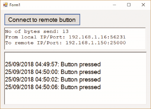
Fig. 11
Now that we have the application let’s continue with the description of the logical communication flow with Arduino. In the first part of the code, we find the import of the .NET Framework libraries (” Imports …”). These libraries have the same function as the Arduino libraries: they simplify the programming phase by providing ready-to-use “bricks”. Immediately afterwards, we see a block consisting of definitions of variables that we will need in the course of the application. From here you can immediately see that we have also defined here the IP address and port of the Arduino board: in fact, we are in a phase in which the Visual Basic application knows how to contact Arduino, but Arduino still does not know how to communicate with the application.
Listing 4
Imports System.ComponentModel
Imports System.Net
Imports System.Net.Sockets
Imports System.Text
Public Class Form1
Dim udpClient As UdpClient
Dim GLOIP As IPAddress = IPAddress.Parse(“192.168.1.150”)
Dim GLOINTPORT As Integer = 25000
Dim senddata As Byte() = New Byte() {}
Public receivingUdpClient As UdpClient
Public RemoteIpEndPoint As New System.Net.IPEndPoint(System.Net.IPAddress.Any, 0)
Public ThreadReceive As System.Threading.Thread
Dim SocketNO As Integer = 0
Dim receiveBytes As [Byte]()
Dim strReturnData As String
Dim noBytesSend As Integer
Dim IPEP As IPEndPoint
Dim message As String
Private Sub btnConnectToRemoteButton_Click(sender As Object, e As EventArgs) Handles btnConnectToRemote-
Button.Click
‘ Invia i parametri a Arduino
udpClient = New UdpClient
udpClient.Connect(GLOIP, GLOINTPORT)
senddata = Encoding.ASCII.GetBytes(“Connessione OK”)
noBytesSend = udpClient.Send(senddata, senddata.Length)
RichTextBox1.Text = “N. di byte inviati: “ & noBytesSend & vbCrLf
RichTextBox1.Text = RichTextBox1.Text & “da IP/Porta locale: “ & udpClient.Client.LocalEndPoint.
ToString & vbCrLf
RichTextBox1.Text = RichTextBox1.Text & “a IP/Porta remoto: 192.168.1.150:25000”
bgw.RunWorkerAsync()
End Sub
Private Sub bgw_DoWork(ByVal sender As System.Object,
ByVal e As System.ComponentModel.DoWorkEventArgs) _
Handles bgw.DoWork
SocketNO += 1
IPEP = New IPEndPoint(GLOIP, GLOINTPORT)
receiveBytes = udpClient.Receive(IPEP)
message = Encoding.UTF8.GetString(receiveBytes)
End Sub
Private Sub bgw_RunWorkerCompleted(
ByVal sender As Object, ByVal e As RunWorkerCompletedEventArgs) _
Handles bgw.RunWorkerCompleted
RichTextBox2.Text = RichTextBox2.Text & vbCrLf & DateTime.Now & “: “ & message
Dim audio As New System.Media.SoundPlayer
audio.SoundLocation = “Doorbell.wav”
audio.Load()
audio.Play()
bgw.RunWorkerAsync()
End Sub
End Class
The information is transmitted to Arduino by pressing the button that we have called here btnConnectToRemoteButton: inside the subroutine (which in Visual Studio is called “method”, regardless of whether it is a Function, i.e., a piece of code that returns a value, or a Sub, i.e., a subroutine that does not return any value) we open the communication to the IP and the Arduino port and send it the string “Connection OK”. For debugging purposes, in the first RichTextBox control we display the number of bytes sent to Arduino, the address/port of the local PC and the address/port of Arduino. Immediately afterwards, we see a strange instruction: bgw.RunWorkerAsync(), probably highlighted with a red underline. This error report is because we have not yet added the BackgroundWorker control:
- momentarily return to the window defining the graphic interface of the application;
- in the ToolBox look for the BackgroundWorker control and double-click on its name: this will cause the control to be added at the bottom of the graphics window;
- click on BackgroundWorker1 (the default name) and in the Properties window search for the Name property and replace the string with dgw;
- now go back to the code editing window, and you will see that the underlining is no longer there: problem
The problem of understanding what the BackgroundWorker is for is still unsolved, so let’s explain it immediately. With the traditional programming, that is the passage of the control of the program to a specific subroutine or any way to a set of instructions that would wait for messages coming from the external connection, we will obtain the total block of the user interface. One possible solution is to use multithreading, creating a separate thread in which to run instructions that collect external messages and pass them to the user interface. However, this method is somewhat problematic because a secondary thread cannot directly modify the user interface. The best solution is therefore to use a BackgroundWorker that is in charge of a single task, i.e., to execute the code contained in the subroutine bgw_DoWork, and to perform specific actions at the end of that task, represented by the instructions contained in the subroutine bgw_RunWorkerCompleted. In our logical path, we have now arrived at the PC application that has sent its IP address and brings it to Arduino. We then return to the latter to see the last part of the sketch. In the loop() section we first have an instruction that parses the data packet that came from the Wi-Fi connection. This is the only package that will come from the PC and therefore the if block (packetSize) will be executed only once, recording the IP address and the port of the PC and displaying some information about the serial. The next block will be executed each time we press the button connected to Arduino. When this action is detected:
- will be written “button pressed” on the serial port;
- the LED will be on for about one second;
- will be emitted a sound from the buzzer, also this for about a second;
- a message will be sent via UDP to the PC, to warn it that someone has pressed the button.

Fig. 12
The IpAddress2String function is only intended to convert parts of the IP address into a string in the classic format nnn.nnn.nnn.nnn. In Fig. 12 you can see all the activities carried out by the Arduino board, including the messages exchanged with the PC. Well, now we’ve sent a message to the PC, so let’s go back to the Visual Basic application to see what happens. The bgw_DoWork subroutine waits for a message to arrive and then notices that a message has arrived, receives it and encodes it in UTF8 format, saving it in the message variable. At this point, automatically, the subroutine bgw_RunWorkerCompleted is triggered, which displays the information in the second text box, emits the sound of a two-tone bell and then triggers the BackgroundWorker again to put it in standby mode for a possible new message. In Fig. 13 you can see a summary of the messages exchanged between the Arduino and the PC, taking into account that those related to the pressing of the button connected to the Arduino (i.e., what we have called “remote doorbell”) are sent repeatedly with each press.
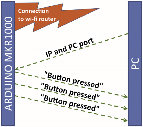
Fig. 13
CONCLUSION
In this article, we have explained the use of the Wi-Fi module included in the Arduino MKR1000, the preparation of the development environment Visual Studio 2017 for the creation of sketches for Arduino and applications able to interface with microcontroller cards, the use of the UDP protocol and even the use of a BackgroundWorker able to do a job “behind the scenes” without blocking the user interface of the application. They are a good basis on which to support you in developing any type of application.
FROM OPENSTORE

Related Posts


-
 Arduino ISP (In System Programming) and stand-alone circuits
We use an Arduino to program other ATmega without...
- Posted 12 years ago
-

-

-
 GSM GPS shield for Arduino
Shield for Arduino designed and based on the module...
- Posted 12 years ago
-
 Small Breakout for SIM900 GSM Module
Some post ago we presented a PCB to mount...
- Posted 13 years ago
-
 Join Maker Faire Rome 2024: Innovation Unleashed at Gazometro Ostiense | Calls Now Open!
All Calls Now Open for Maker Faire Rome 2024...
- Posted 2 weeks ago
-
 Building a 3D Digital Clock with Arduino
Project to create a digital clock consisting...
- Posted 4 months ago
-
 Acoustic amplifier – in DIY Kit
This kit creates a microphone amplifier with an output...
- Posted 5 months ago
-
 Creating a controller for Minecraft with realistic body movements using Arduino
Project of a controller that maps body movements...
- Posted 5 months ago
-
