Let’s experiment and prototype applications via the wireless board based on the ESP8266 module.
Let’s get back to the discussion of the ESP8266 chip, in which we described the new Fishino board, whose major elements are the ATmega328 microcontroller and the ESP03 module, the latter being based right upon an ESP8266 chip. In this case, the module operates only as a Wi-Fi interface, and the board lets the Atmel chip handle the functions required by means of specific command.
In addition to the Wi-Fi interface, the small ESP03 board includes even a programmable microcontroller, thanks to which we could create this demoboard, that enables the creation of wireless applications, in an even easier way and with a limited amount of components. With this board, it is as if having a ready-to-use microcontroller with an integrated Wi-Fi. Not bad… Isn’t it?!
As hinted before, the module is a completely autonomous one, however it is needed to access it via PC, in order to program it; therefore we included an USB/Serial Converter that enables the download of the program to be executed into the ESP8266 module’s flash memory.
Circuit diagram
The demoboard we propose in this article includes the essentials needed in order to create simple applications, that is to say the USB/Serial Converter and other few components required for the functioning. Among these we will find a voltage stabilizer, some strip connectors and some buttons that simplify the module’s management.

From the diagram’s analysis it is possible to notice that a button (the PROG one) is connected to the ESP8266 chip’s GPIO0 pin, and that it is used in order to activate the module’s boot mode function; while the RST button, connected to the CH_PD pin (Power Down) is used as a module’s hardware reset. The strip connectors simply make the ESP8266 chip’s pins available, thus facilitating the connection to external peripherals, by means of small jumper cables. The board supports the usage of the ESP01 and ESP03 modules; we would like to point out that, while the first one uses a strip connector and thus may be easily substituted, the second one has to be directly welded on the printed circuit board, and this may complicate a possible substitution.


On the other hand, the ESP01 makes only a limited amount of pins available. In this article we will refer to the board’s usage via the ESP03 module. From the EXP8266 chip’s internal configuration analysis (the chip is the heart of the ESP03 module), it is possible to notice how it has all the functions that are typical of a microcontroller having a 32-bit architecture; in addition to the UART communication module, it has the high-speed SPI interface and the I²C interface. All the pins can be configured as inputs or outputs, and some of them even as analog inputs while the analog outputs can be obtained by means of the PWM signal that is available on some pins. The electric features and the performances can be compared to those of the Atmega328 microcontroller, that is equipped by Arduino Uno: thus the development of similar applications is possible, with the only difference being that the power source is a 3.3V one, as opposed to the 5V used by the Arduino board.

How to configure the module
Let’s see now how to configure the module for a stand-alone functioning: the operation is not a difficult one, but it must be executed while paying a certain attention. The solutions are essentially two, and they have been developed as a result of a collaboration with the community, that got interested in the module and that took advantage of the SDK provided by the manufacturing firm, when compiling the new firmware.
The first solution regards a project named NodeMCU, whose website (the language is Chinese, but English is among the options).
The project sources and all the relevant files are available at the github website.
As a first thing, the firmware must be installed: it must be capable of supporting the stand-alone functioning, and to do so we used a dedicated software, named ESP8266Flasher.exe and that is available for 32 and 64-bit Windows systems.
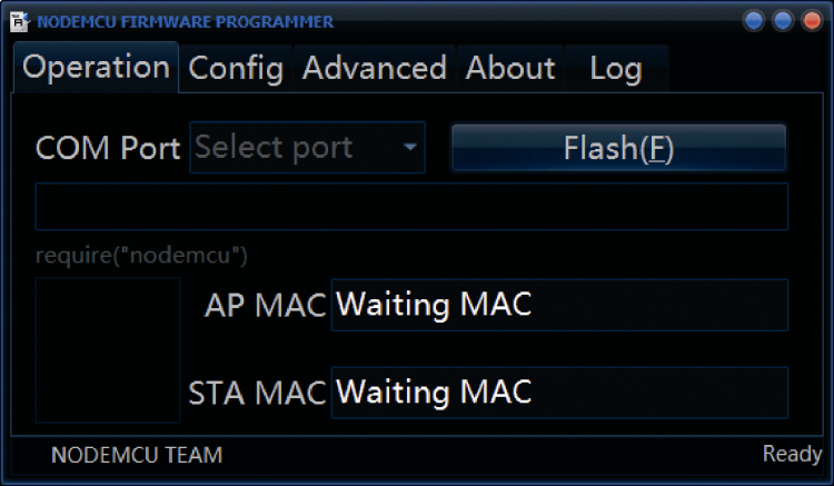
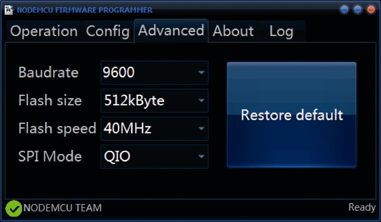
Please make sure that the module is connected to the PC, then boot the software and set the Baudrate at 9600 (but even higher Baud rates are allowed), the Flash Memory size at 512 kBytes, the speed at 40MHz, and finally select SPI as the QIO mode.
The firmware we used is contained in the nodemcu_integer_0.9.5_20150318.bin file, thus please open it from the dedicated menu. While in the demoboard mode, please press and keep the PROG button pressed, then operate for a moment on the RST button in order to start the module in boot mode, and then click on the software’s Flash button so to start the firmware’s writing; from the software’s LOG board you will be able to see the executed operations.
As soon as the download is started, it will be possible to release the PROG button. If everything reached a successful conclusion, a small green icon will appear down and on the left.

At this stage, it is possible to interact with the module, by means of appropriate program environments, the simplest and most immediate one of them being named ESP8266LuaLoader. It is available on the Internet; The file to be booted is named LuaLoader.exe.
As soon as this IDE is booted, and the communication with the module has been established (from the Settings menu), you will be able to work with it in a simple and immediate way. Now please connect a LED having a 220 Ohm resistor, in series, between the GPIO2 and the GND pins. After that, please try to manage it: you will have to use the commands in the blue box, in order to set the pin as an output (Set button) and to turn on and off the LED, by means of the 0 and 1 buttons.
Please use the commands in the orange box in order to set the Wi-Fi network; the Survey button allows you to know the available APs (Wi-Fi Access Points): by inserting the network’s name and the password the access is possible. The GEP IP button will show the IP address assigned to the module by the router. These first examples allow the testing of the module’s functioning and of the whole hardware, but still the module is not yet completely autonomous. In fact, when booting the module, it is set so to start the init.lua sketch, that will contain all the instructions needed in order to carry out the expected task. Therefore, let’s see how to program the module in a permanent way.

Let’s start with an example: please open the WebServer_toggle_pin.lua file with a common text editor (such as Notepad)
you will find it in the LuaLoader program’s sample folder. Please then modify the SSID and PASS entries at the wifi.sta.config(“SSID”,”PASS”) line, with the data from your network, being respectively your name and login password. While in the orange box, please select the file you want to start (in our example, it is WebServer_toggle_pin.lua) and click on the dofile command, so to execute the instructions here contained.

Please open the browser and insert the IP address you will see on screen, thus you will have the possibility to remotely turn the LED connected to GPIO2 on and off.

As already seen, the module at the start is set so to boot the sketch named init.lua, that will contain all the instructions needed by the task to be carried out; thus, once you will have decided the file to be used, you will have to rename it as init.lua and to load it on the module: at each boot this sketch will be started and the instructions therein will be executed.
The connection between the module and the PC is no longer needed, thus it is enough to power the board by means of a 5V voltage, via the USB port, and that’s all it takes.
For such a function, the batteries used to charge smartphones may prove useful; some of them can be found as advanced versions that enable the recharge by means of solar energy.
With such products, it is in practice possible to power the board for an unlimited period of time, provided that enough sun exposure is assured for the duration of the battery charge.
Obviously, even a simple 5V stabilized power supply will be fine, such as one of those used as battery chargers for the smartphones.
Let’s see now other examples, by using an alternative management: that’s the case of the application named ESPlorer that can be downloaded.
Even this one (as for the other programs) does not need an installation, but requires that the Java environment has been installed on the PC; the file to be booted is named ESPlorer.jar.
Please select the sample file named WebServer_toggle_pins.lua and rename it as init.lua, then open it from the File>Open from disk menu and load it on the module, via the Save to ESP command.

Then reboot the module via the Reset ESP command, or launch the file via the DoFile command; on screen the IP address assigned to the module by the router will appear: please insert this address in the browser so to verify the web server operation.

Let’s analyze the listing, so to better understand the functioning. The first lines are used for the connection to the Wi-Fi network (in this case, the home router) and, as we could see, they have to be modified by adding the network’s name and the login password; the sketch will provide to print the IP address assigned by the router:
wifi.setmode(wifi.STATION)
wifi.sta.config(“SSID”,”PASSWORD”)
print(wifi.sta.getip())
The following lines are needed in order to set the GPIO pins as outputs, and to boot the server, that has to be tuned in to port 80, the default one for the html requests:
led1 = 3
led2 = 4
gpio.mode(led1, gpio.OUTPUT)
gpio.mode(led2, gpio.OUTPUT)
srv=net.createServer(net.TCP)
srv:listen(80,function(conn)
When a request arrives from the client (the browser), it is be processed by the function:
conn:on(“receive”, function(client,request)
that will provide to verify if the request is html standard compatible, afterwards it will provide to build the answer string, that is to say the page that will be sent to the client for its visualisation. From the client’s request, the string related to the command (ON or OFF) used for the LEDs’ activation or deactivation is extrapolated; the corresponding code is the following one:
if(_GET.pin == “ON1”)then
gpio.write(led1, gpio.HIGH);
elseif(_GET.pin == “OFF1”)then
gpio.write(led1, gpio.LOW);
elseif(_GET.pin == “ON2”)then
gpio.write(led2, gpio.HIGH);
elseif(_GET.pin == “OFF2”)then
gpio.write(led2, gpio.LOW);
end
The programming may not appear so spontaneous, but by taking the cue from the many examples supplied, and with some tries, it will be possible to obtain all the desired functions.
For example, the file named googleTime.lua regards another interesting sketch, that will enable the usage of the module as a web client used in order to request time and date from Google’s servers.

In this case the sketch starts by creating the connection to Google’s server by means of the following line:
conn=net.createConnection(net.TCP, 0)
conn:connect(80,’google.com’)
As soon as the connection has taken place (conn:on) a HTTP request is sent to the server Listing 1.
Listing1
conn:on(“connection”,function(conn, payload)
conn:send(“HEAD / HTTP/1.1\r\n”..
“Host: google.com\r\n”..
“Accept: */*\r\n”..
“User-Agent: Mozilla/4.0 (compatible; esp8266 Lua;)”..
“\r\n\r\n”)
end)
The following function deals with processing the return string and with extrapolating the requested data, so to then display them on screen (Listing 2). As a subtlety, the time needed in order to complete the request is returned as well.
Listing2
conn:on(“receive”, function(conn, payload)
print(‘\nRetrieved in ‘..((tmr.now()-t)/1000)..’ milliseconds.’)
print(‘Google says it is ‘..string.sub(payload,string.find(payload,”Date: “)
+6,string.find(payload,”Date: “)+35))
conn:close()
end)
Working with Arduino IDE
As you will have noticed, even if there aren’t big issues, the programming is not really the simplest one; for such a reason the community moved towards making Arduino IDE compatible with this module (in the end, the microcontroller aboard is not that different from the one installed in an Arduino board).
As a first thing, it is needed to install the last Arduino IDE’s version (at the time we are writing, that’s 1.6.5); in the recent releases, the IDE, in addition to being a multi-platform one, has also become a multi board one, thus it is used in order to program different kinds of boards, simply by installing some additional packages with the procedure described below.
Please open the IDE and select the File>Impostazioni menu, afterwards please type in the address in the Additional board manager URLs field, found in the window now appearing. Now, in the window that can be accessed via the Strumenti>Scheda>Board manager menu command, please install the esp8266 by ESP8266 Community package. The ESP8266 chip support is now available.

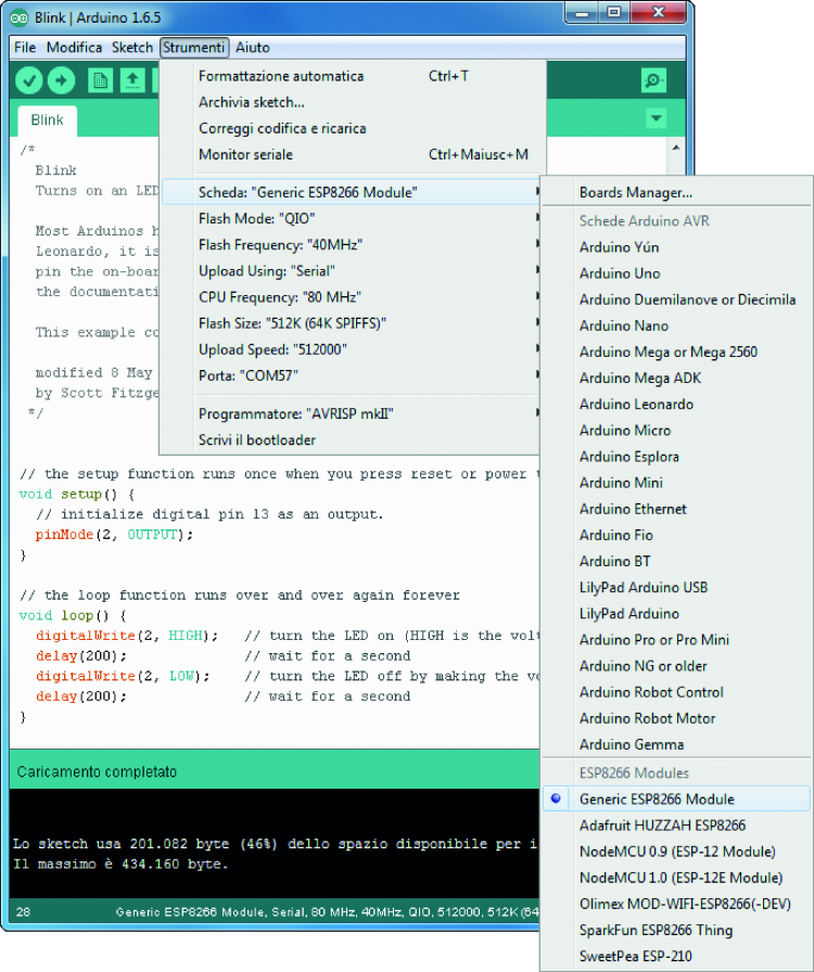
Should you encountered any problem, during this procedure, you may go see the reference website. If everything went well, on the other hand, please reboot the IDE and select Strumenti>Scheda>Generic ESP8266 Module that can now be found there; make sure that the settings are the ones shown in figure (Generic ESP8266 Module, Serial, 80 MHz, 40 MHz, QIO, 512000, 512K) and open the blink example concerning a LED flashing (it may be opened from the File>Example>01.Basic menu), then modify the used pin (13) by means of our GPIO2 (2), to which you will have connected a LED having a resistor in series. At this stage you will have to transfer the program in our ESP module, that we therefore have to bring to boot mode with the usual procedure: please keep the PROG button (GPIO0) pressed, and press the RST (CH_PD) button for a moment.
Please click on the Carica button (the one having an arrow), as you would do when loading a sketch in Arduino, and wait for the operations to be completed; as soon as the download procedure has been started, you will be able to release the PROG button. As you will have realized, we didn’t use the autoreset function that is normally carried out in a manual way, when bringing the module to the boot mode. If you had any problem, when loading, you may decrease the speed from 512000 to 115200 Bauds. Once the loading has been completed, please press the RST button so to boot the module and to start the sketch; the LED will start to flash. If everything worked fine, you may immediately experiment with other applications, the most classic one being the web server having the HelloServer sketch, and available among the examples for the ESP8266 module. In order to load and boot the sketch, please follow the procedure we just described, with a variation: before resetting the module, please open the Serial Monitor and set the communication speed to 115200 Bauds; this will allow you to see the IP address assigned to the module by your router. Please open the browser and type in the address that has just been displayed, so to see the web server operational. The available examples are really a lot, and in practice include every relevant application.
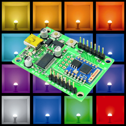
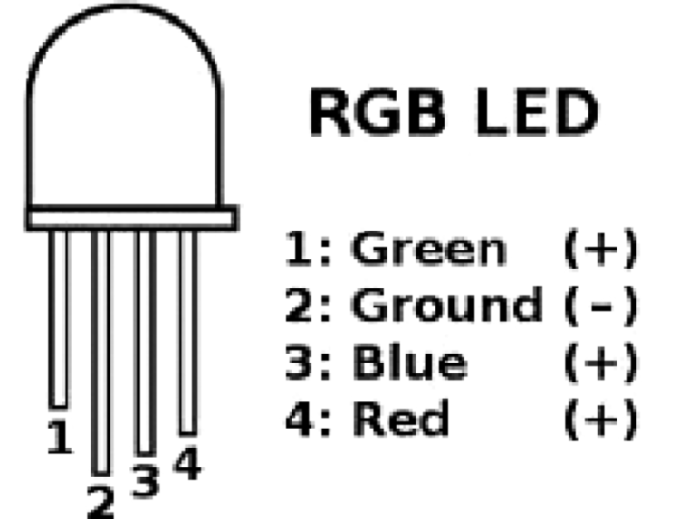
We have however decided to propose our custom application, consisting in a simple lamp: from a smartphone, it is possible to control its turning on and off, and the colour variation. As a first thing, we have to connect a RGB LED to the ESP03 module’s PWM outputs: to be precise, it’s the pins 12, 13 and 14, that will respectively command the three primary colours, being red, green and blue. Each LED will need a resistor in series, so to guarantee a current of about 10 mA.

The general formula used in order to calculate the electrical resistance is R=(Vcc-VF)/0,01, with Vcc being the supply voltage (3,3 V in our case), while VF is the voltage drop on the diode. In the case of the red LED, the VF is worth about 1.7 volts, so the series resistance is worth about 150 ohm; as for the green and blu dioedes, the voltage drop is 3 volt, thus the resistance is about 33 ohm.
Once the hardware has been prepared, we may deal with the software part, that is to say, the sketch to be loaded in the module: given the kind of application, it seems natural to implement a communication of the UDP (User Datagram Protocol) kind that, even if not guaranteeing the proper data reception (it does not implement the receipt confirmation, nor the resending of the corrupted data), has the advantage of not suffering of latency times, and considers the possibility of sending data from a server to several clients at the same time, without the need to establish a communication, that is to say, without having to insert the IP addresses.
It is precisely this last peculiarity that is relevant in our project, since if we had to install more lamps in the same room, all of them would have to be controlled together via the same application; it would be the same if we placed them in different rooms, as long as each lamp has access to the same Wi-Fi network.
Each demoboard will have to be powered independently, and to be connected to the home Wi-Fi, while waiting for the UDP messages that will be the commands used in order to manage the RGB LED. The sketch for the ESP8266 can be easily understood; we may analyze its essential lines: for an UDP communication we chose the all-purpose 8080 port, and this is the only parameter needed so that only the communications addressed to the same port may work.
On the other hand, the 0.0.0.0 address is a generic address, so to indicate a transmission towards everyone:
unsigned int localPort = 8080;
IPAddress serverIP(0,0,0,0); // Broadcast communication
The program’s part concerning the setup sees to turning the LED on, with a red light, as soon as the board is powered; an attempt to connect to the Wi-Fi network follows. Before loading the program, it is needed to set username and password, so to access the home network.

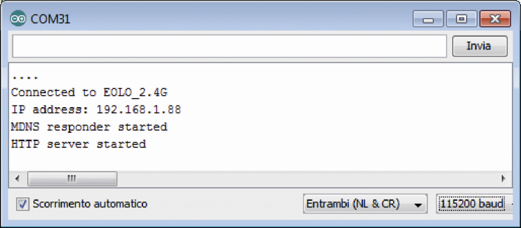
As usual, the sketch must be adjusted, by typing in the SSID and your network’s password. The sketch sees to the printing of the IP address assigned by the router (even if this piece of information is not needed); the booting of the UDP client then follows. We provided that – once it is powered – the board will make the red light lamp turn on and, once the connection to the network reaches a successful conclusion, it will emit a green light flashing for the duration of two seconds (Listing 3).
Listing3
void setup()
{
setColor(255,0,0);
Serial.println();
Serial.begin(9600);
// We start by connecting to a WiFi network
Serial.print(“Connecting to “);
Serial.println(ssid);
WiFi.begin(ssid, pass);
while (WiFi.status() != WL_CONNECTED) {
delay(500);
Serial.print(“.”);
}
Serial.println();
Serial.println(“WiFi connected”);
Serial.println(“IP address: “);
Serial.println(WiFi.localIP());
Serial.println(“Starting UDP”);
udp.begin(localPort);
Serial.print(“Local port: “);
Serial.println(udp.localPort());
setColor(0,255,0);
delay(2000);
setColor(0,0,0);
}
The veritable program is contained in the loop function, and it simply sees to the reading of the data received, and to their processing (Listing 4).
Listing4
void loop()
{
int packetSize = udp.parsePacket();
if (packetSize)
{
int len = udp.read(packetBuffer, 255);
if (len > 0) packetBuffer[len] = 0;
int R = packetBuffer[0];
int G = packetBuffer[1];
int B = packetBuffer[2];
setColor(R,G,B);
}
delay(100);
}
The packetSize variable will take a value greater than zero, once messages have arrived; in our case, these last ones will simply be three bytes, each one containing the RGB values for the brightness.
These three bytes will be read and converted in whole numbers (with a value between 0 and 255), and thus used so to set the brightness of the three LEDs, by recalling the setColor function.
The setColor function uses the three values so to set the three PWM channels by means of the well-known analogWrite function, on the three assigned pins. In order to send the command for the RGB LED’s management, we thought about using a specific app, available for Android devices, and called TCP UDP RGB; it may be acquired on the Web.. It is a very simple app, but an extremely effective one, and also very easy to use; the only settings required are the IP address and the communication port. As for our home network, the IP address to be assigned is 192.168.1.255 and the port is the 8080 one, that is to say, the transmission will occur on the 8080 port for all the devices whose IP address starts with 192.168.1.xxx. From the main screen it is possible to send the management commands for the RGB LED, by separately choosing the red, green and blue values, with the possibility to save up to 10 customized values. In order to obtain a better result from the point of view of the brightness, we suggest to enclose the RGB LED with some semi-transparent paper, that carries out a diffusing function.

By amplifying the output signal from the ESP module, by means of some transistors, it would be possible to use a power RGB LED, so to obtain a luminous flux that is powerful enough to create a nice, customizable diffused light in the room.

FROM OPENSTORE
ESP03 module Wi-Fi transceiver – GPIO

[…] The traditional alarm system which just makes a sound alarm go off and maybe sends out an SMS, forcing you to cash out for recharging the built-in Sim Card, is not enough for you? Have you decided to take advantage of a simple and intuitive system in order to receive access notification anywhere in the world, even your cell phone, over the Internet? Are you beginners of the Arduino and IOT word and you would like to start out with a good and exciting project that will show your friends what you can do? Well, you don’t need to worry, because we have developed an ideal project to satisfy all your needs, based on the ESP03 Wi-Fi module and operating in the security field, which we are going to describe in these pages. In fact, the circuit is an alarm system that takes advantage of the “ESP03 demoboard” for the ESP03 Wi-Fi module, described in the post: Let’s play with the ESP-03 Demoboard […]