
During the months spent developing OpenWheels, we worked hard to achieve a firmware that was both functional and fast. We used float type variables only when it was strictly necessary and we implemented a system interrupt to manage, with the right timing, the stabilization operations. We did not skimp on protection systems and diagnostic messaging because, as an open source project, it must be easy to manage.
Despite the hardware has already been described in previous articles, a small but crucial detail remained suspended: the scale of the gyro. In the first tests we used the gyroscope with a scale of 30 °/sec – definitely the optimum value when Openwheels is moving – which, however, in some situations led to a reading overflow. It is important to exploit the sensors with their maximum capacity, so that the ADC converter used for reading can reach the full range of values; for this reason the control board included two jumpers (JP3 and JP4), to tweak the scale. To avoid going out of scale with the gyroscope samples, we later preferred to switch to a 120 °/sec scale, a function obtained by shortcutting the JP4 jumper and no longer the JP3.

LCD Settings
The management of all user customizable parameters is made through the LCD display, which also performs the function of monitoring the main diagnostic values. There are three screens that can be displayed in sequence by pressing the “Enter”.
Screen number 1 (default) indicates the battery level, the operation status, if in error state, also the relative code. Because there may be several error situation, which also can occur at the same time, this information is displayed only in the telemetry software, while the LCD displays a sequence of bits, each corresponding to a specific error as reported in Table 1.
LCD Encoding errors
| bit | Signaling |
| 0 | If “1” indicates that the engine driver is active |
| 1 | If “1” indicates that the battery voltage is below the minimum threshold |
| 2 | If “1” indicates that the battery voltage is above the maximum threshold (not implemented) |
| 3 | If “1” indicates that the current drawn from the battery has exceeded the maximum |
| 4 | If “1” indicates that an error occurred in reading the steering potentiometer |
| 5 | If “1” indicates that there is a error in the reading of the accelerometer |
| 6 | If “1” indicates that an error occurred in reading the gyroscope |
| 7 | If “1” indicates that there is an error in the calculation of the angle |
| 8 | If “1” indicates that there is a error in the parameters contained in the EEPROM |

The screen you can see – the first of the normal sequence – in which we simulate the LCD display, it indicates that everything runs smoothly, OpenWheels is in Standby mode and the battery is at 56%
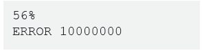
This screen shows instead the 10000000 error code which corresponds (see table) an error in the evaluation of the angle. This situation occurs, for example, if you tilt Openwheels.
All errors, except for the 0 bit, require immediate Standby mode and the consequent shut down of the power driver.
Chances are that when turned on, since all the values in the EEPROM are null, you’ll see the error on bit 8; we will see later how to set the operating parameters. Note that the error code does not display insignificant zeros to the left, so if the error is in bit 5 will “ERROR 100000” and so on.
While the error screen is displayed, by pressing P1 and P2 at the same time you get the restoration of all functions.
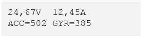
The second screen shows the information relating to the battery voltage and its output current on the first line, while the second shows the values of the accelerometer and gyroscope as read from the ADC of the microcontroller. These are the raw values (RAW): the accelerometer data is averaged to remove a small part of the intrinsic noise.
From this screen, by pressing both P1 and P2, you can enter the section on setting the PID parameters. The setting of the P, I, D is via the P1 and P2 buttons: after selecting the parameter to change with Enter.
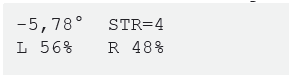
The third screen shows, with the first line, the value of OpenWheels inclination angle and the value regarding the steering; in the row below it also shows the values for the voltage sent to both left and right motors (a negative value corresponds to the reverse rotation of the wheels).
For the proper functioning of OpenWheels just verify that angle values increase by tilting the handlebar forward and by tilting the steering on the right handlebar.

From this screen, by pressing the P1 and P2, you start the procedure to set accelerometer and gyroscope zeroes; it is critical that during this procedure OpenWheels remain perfectly motionless in the vertical position. These values will be stored in the EEPROM, so then you can use OpenWheels immediately without the need to perform the calibration every time. It is essential to perform this procedure when you first start and whenever OpenWheels tends to move in a vertical position.
When powering the OpenWheels board, a series of initialization parameters – that may be visible through the Arduino IDE Serial Monitor function – are sent through the serial port. During the ignition phase a set of objects are initialized: the LCD display, the registers that will be used for the control of the PWM modules and interrupt, the neutral value of the handlebar and of the
current sensor. Some parameters are then sent via the serial port that will be used by the firmware: the reads from the EEPROM memory that are used by the PID control, the scale used for the steering (SteerScale), the values of the zeroes (Steer_Zero, Acc_Zero, Gyro_Zero, IBat_Zero).
Adjusting the PID
Let’s now set the parameters of the PID control and how they affect the operation. Initially the parameters should be set to zero and then modified carefully following the directions below. Do not press START if you have not first cleared all the PID parameters and set the zeroes (with all the parameters to zero by pressing the START button engine power will not be supplied, the display will however show RUN to indicate that the drivers have been activated)
To ensure maximum safety, we included the Soft-Start function that allows you to operate the motors gradually when you press the START button, avoiding abrupt movements of the vehicle. In fact, it may happen to have OpenWheels slightly tilted, pressing the START button, you would have an abrupt start. Thanks to the Soft-Start function, when you press the START button, the engines are operated gradually in about two seconds, which is sufficiently smooth to avoid dangerous situations; the word STANDBY is replaced by the word RUN on the display only after it has finished the Soft-Start procedure: you can now hop on and ride.

The first parameter to be updated is the proportional term (P), which essentially indicates how fast OpenWheels goes according to the inclination of the handlebar; a high value means that OpenWheels will be very sensitive to the inclination of the handlebar, so very responsive. To become familiar with the vehicle, we recommend you starting with a low value, such as 50, and possibly raise it later, in steps of five, after becoming used to it. Now if you try to press the START button (but not necessarily standing on it) you will see that by tilting the handlebar OpenWheels picks up speed; if you try to climb you will notice that you’ll feel hard to remain in balance. Remember that OpenWheels needs to have the right settings and is therefore not guaranteed to work perfectly at this early stage; you must also take into account inevitable incidents with this type of vehicle, therefore we recommend that you always use the utmost caution in adopting protective systems such as helmet, knee pads and wrist guards
The next step consists in adjusting the derivative parameter (D): it acts on the stability of OpenWheels because it affects the engines as a result of sudden changes of inclination. It is good to start from zero and gradually raise it slowly, as you get familiar; values that are too low prevent the stabilization and, while driving OpenWheels, you tends to fall forward or backward, while too high values tend to carry a overcompensation in which the engine begins to vibrate.
Proceed step by step, gradually raising the one (P) and the other (I) parameter, until obtaining the complete stability of the vehicle.
Let’s now look into the Integrative Parameter (I) : while being in fact part of the stabilization cycle, it affects the mode of conduction in the long term. In fact, when you reach a certain speed you need to keep leaning forward on the handlebars and consequently you will rest your feet on a platform that is tilted and this can be inconvenient in the long run. The integrative parameter, essentially, progressively increases the speed of the vehicle. Being ourselves, through the handlebar angle, to adjust the speed, this translates into a natural and progressive withdrawal of the handlebar, allowing to reach the desired cruising speed but with the platform in a horizontal position. We need to be very careful with this parameter because the automatic increase in speed can be dangerous if you are unable to manage it; we recommend you to start from zero and work for increments of one unit, with the utmost caution

A fourth parameter called Steer allows you to set the sensitivity of the steering; from our tests we have seen that 75 is an optimal value. The higher this parameter, the greater the steering will be in proportion of the tilt (right and left) of the handlebar. OpenWheels has a high maneuverability, and is able to rotate on itself from a standstill, however, this could be a problem at high speed because it would be possible tacks so narrow as to become dangerous. For this reason we have equipped our vehicle of sort of a progressive steering in which the sensitivity of steering varies according to the vehicle speed; in this way you will perform very tight turns when at low-speed (even rotate on yourself), while, as you increase the speed, curves will be less steep. This is also a safety mechanism to prevent to involuntarily do dangerous maneuvers that jeopardize the safety of the passenger
The main parameters, commonly used, can be changed via the LCD display, while others can be set only by editing the appropriate lines of the program: those are more specific parameters that we recommend you to change only when in possession of the necessary knowledge.
Parameters in the firmware

These values are given in the first lines of the firmware’s main module, among them we find the Cycle_Freq parameter that refers to the frequency (Hertz) of the cycle stabilization. You would want to increase this value in an attempt to enhance the performance of OpenWheels but actually, given the masses involved, it doesn’t require too high frequencies and it is also necessary to deal with the limited time available for mathematical calculations. Some parameters are needed to define the power status. First, among them you can find VBatScale that defines the scale in measuring the voltage of the battery; the value is related to the voltage divider formed by the resistors R10 and R11. The VBatLmax parameter indicates the voltage value for which the battery is considered fully charged, while the value VBatLmin is the value below which the battery is considered discharged. This also results in an error state and the consequent STANDBY state of OpenWheels. All these parameters have already been set taking into account the evidence of the tests we have done, but it is likely that some of them – such as the current limit or the minimum battery voltage – can be modified on the basis of new evidences.
A serious problem that we met during testing concerned the stabilization of the vehicle with varying supply voltage: in fact when the battery voltage drops, the engine voltage decreases proportionally and the necessary power, to control the vehicle, lacks. To avoid this, we read the voltage of the battery and use this info to compensate the engine throttle so as to be independent from the charging state of the battery. In this way performances – including the maximum speed – are thus constant until the complete battery discharge.
While reading the battery current, the IBatScale parameter defines the scale with which this value is is derived based on the value measured from the U1 current sensor. The IBatMAX value is of utmost importance as it defines the maximum current delivered by the battery beyond which OpenWheels goes immediately into the STANDBY state. In the firmware, variables IbatLevel and IbatLevelSmooth refer respectively to the measurement of instant current (measured at each cycle) and the average one. The actual value is used to limit the maximum current consumption, while the average value is used for telemetry. In the module called IMU you’ll find Acc_Scale and Gyro_Scale values that refer to the scale adopted for the two sensors in the circuit board. We have already explained how to derive these values, their modification is only necessary if you use a different type of sensors.
In this section we will now go through the firmware and we will to understand how the functions used in the OpenWheels sketch are implemented. Even before starting the project development, we had doubts as to whether the small Arduino microcontroller board could withstand the onerous tasks related to stabilization. After the first trial sketch, we realized that the stabilization does not really need a lot of lines of code, the difficulty comes when, in addition to stabilization, you must manage the acquisition of the signals from the various sensors, the management of telemetry and of the display, in addition to the implementation a whole series of security systems.
Stabilization is determined by a PID control in which the proportional parameter takes into account the value of the angle, the derivative parameter takes account of the extent of the gyroscope and the integrative parameter is eventually determined by a mathematical accumulator; all in accordance with the basic equation:
Drive = P·Angle + I·Accumulator + D·Gyro
Overall, the PID control is made of a few lines of code:
void PID()

{

//Implement PID

Pval = float(KP) * Angle;

Accumulator = Accumulator + Angle*0.01;

Accumulator = constrain(Accumulator, -100, 100);

Ival = float(KI) * Accumulator;

Dval = float(KD) * Gyro_Rate;

drive = (Pval + Ival + Dval)/10;

}
The Gyro_Rate varibile is directly determined by reading the gyroscope, while the estimation of the inclination angle is determined thanks to the complementary filter calculated on the basis of Angle_Rate and Gyro_Rate,as already described in the previous part of the post.
void AccAngleMeasure()

{

Acc_RAW=0;

for (i=0; i<10; i++)

{

Acc_RAW += analogRead(Acc_ADC_pin);

delayMicroseconds(500);

}

Acc_RAW /= i;

Acc_Angle = float(Acc_Zero-Acc_RAW)*Acc_Scale;

}


void GyroRateMeasure()

{

Gyro_RAW=0;

for (i=0; i<10; i++)

{

Gyro_RAW += analogRead(Gyro_ADC_pin);

}

Gyro_RAW /= i;

Gyro_Rate = float(Gyro_Zero-Gyro_RAW)*Gyro_Scale;

}


void EstimateAngle()

{

// Use complementary filter to fusion acc e gyro data

float Comp_Filter_Constant = 0.03;

float dt=1/Cycle_Freq; // time for cycle

Angle = (1-Comp_Filter_Constant)*(Angle + Gyro_Rate*dt) +     (Comp_Filter_Constant * Acc_Angle);

Angle = constrain(Angle, -30, 30);

}
You’ll note from the sketches that each sensor sampling is performed via an average, that very marked in the case of the accelerometer: that’s in order to reduce as much as possible the intrinsic noise of the sensor. In the estimation of the angle – with the filter algorithm – Comp_Filter_Constant holds particular relevance as it sets the operating point of the two filters. A lower value makes the measurement more perfect but slower, while a higher value makes the measurement faster but more sensitive to the noise of the accelerometer.
The drive variable is not used directly in the engine management because it is necessary to take into account the level of the battery, the inclination of the handlebar (steering) and the soft-start function that avoids sudden movements of the vehicle.
The control of the motors’ driver happens by means of two PWM signals plus a ShutDown control; the latter puts the drive in standby mode with reduced power consumption. The classic Arduino function analogWrite() cannot be used due to two major limitations: first, PWM frequency is fixed and, secondly, the resolution is only eight bits. For a proper control of our engines, the PWM frequency should be set to 16KHz (this value is obtained from experimental considerations also as a result of numerous tests) and the resolution should be at least nine bits.
At this frequency the driver works at the highest possible performance, the engines are very reactive and are not emitted annoying noise during operation. The efficiency is so high that the SMD format MOSFET equipped driver finals are barely warm during operation. We therefore need adequate flexibility in the management of the PWM signal that can be obtained only by acting directly on Atmel’s internal registers controlling the PWM module.
The procedure initMotor() then sets the internal registers called ICR1, and TCCR1A TCCR1B being part of system’s TIMER1 in order to activate phase and frequency correct mode with prescaler set to 1 and modeselect set to 8. PWM frequency can be changed by changing the value in the ICR1 register (16-bit counter) using the formula specified in the sketch. Setting this register with a value of 500 makes the PWM frequency 16KHz ensuring a right resolution of about nine bits. It’s possible to change this value, using ICR1 register but this in fact would imply the variation of the resolution by which the PWM signal could be handled. A ICR1 value set to 250 would lead the PWM frequency to 32KHz but with a resolution of only eight bits: lower frequencies allow higher resolutions. To set the duty cycle of the PWM is necessary to adjust the OCR1A and OCR1B registers; note that the value of the duty cycle is limited between a minimum of 5% and a maximum of 95% in accordance with the capabilities of the power driver that is based on a charge pump technology (bootstrapoperation).
void initMotor()

{

pinMode(ShutDown_pin, OUTPUT);

digitalWrite(ShutDown_pin, LOW);   //ShutDown driver at startUP


pinMode(PWMLeft_pin, OUTPUT);

pinMode(PWMRight_pin, OUTPUT);


// Phase and Frequency correct PWM on TIMER1

//PWM_frequency = (16000000)/(2*Prescale_factor*ICR1)

//ICR1=(16000000)/(2*Prescale_factor*PWM_frequency)


TCCR1A = _BV(COM1A1) | _BV(COM1B1) ; // phase and frequency correct mode. NON-inverted mode

// TCCR1A = _BV(COM1A1) | _BV(COM1B1) | _BV(COM1A0) | _BV(COM1B0) ;   //phase/frequency correct mode.

TCCR1B = _BV(WGM13) | _BV(CS10); // Select mode 8 and select divide by 1 on prescaler

ICR1=500;

// limit for driver compatibiliti  (5% di ICR1A) < drivePWM < (95% di ICR1A)

// stop motor driver=stallMotor=ICR1/2;


maxPWM = float(ICR1)*0.95/2;

stallMotor=ICR1/2;   //250

OCR1A = stallMotor;  //0=0%  ICR1/2=50%  ICR1=100%

OCR1B = stallMotor;

}
The SetMotor() function will finally to set the correct value of the duty cycle of the PWM considering the softstart() function and the value derived from reading of the steering potentiometer on the steering column.
void SetMotor()

{

drivePWM = int(drive * goStart);   // 0 in fase di standby

drivePWM = constrain(drivePWM, -maxPWM, maxPWM);

dutyCycleLeft = stallMotor + drivePWM + Steer;

dutyCycleRight = stallMotor + drivePWM - Steer;

dutyCycleLeft = constrain(dutyCycleLeft, stallMotor-maxPWM, stallMotor+maxPWM);

dutyCycleRight = constrain(dutyCycleRight, stallMotor-maxPWM, stallMotor+maxPWM);

OCR1B = dutyCycleLeft;   //set PWM SX 250+-250

OCR1A = dutyCycleRight;  //set PWM DX 250+-250

}
All the functions described so far must be carried out at regular intervals; in addition they have priority over any other task, you then need to set up an internal interrupt attached to system clock. TIMER2 is set exactly for this: it calls the ISR(TIMER2_COMPA_vect)functionthat provides instruction to be executed, at regular intervals.
So here is the main loop that scans all the operations of the firmware.
ISR(TIMER2_COMPA_vect)

{

bitSet(PORTB, 5);

SoftStart();

AccAngleMeasure();

GyroRateMeasure();

EstimateAngle();

Steering();

Status();

PID();

SetMotor();

SetZero();

Telemetry();

bitClear(PORTB, 5);

}
The activation of PORTB register pin 5 corresponds to Arduino’s LED13 and allows, thanks to an oscilloscope, to accurately measure the cycle time and verify that there are no concurrent operations.
TIMER2 is the eight bit system timer configurable acting on TCCR2A, TCCR2B, OCR2A registers. Its operation is very simple: basing on the increase in OCR2A register value, checked at regular intervals (you can set by tweaking prescaler) itchecks when the register is equal to the value of the count variable and automatically generates an interruption to the main program and the ISR(TIMER2_COMPA_vect) function is called back.
void Init_Timer()

{

//freq_INT = 16000000/(Prescaler * OCR2A)

//OCR2A = 16000000/(Prescaler * freq_INT)


int Count =  15625/Cycle_Freq;


cli();               // disable global interrupts

TCCR2A = 0;          // set TCCR2A control register to 0

TCCR2B = 0;          // set TCCR2B control register to 0

TCCR2A = _BV(WGM21);

TCCR2B = _BV(CS20) | _BV(CS21) | _BV(CS22);  //set prescaler to 1024

OCR2A = Count;               // Set compared value

ASSR &= ~(1 << AS2);         // Use system clock for Timer/Counter2 AS2=1

TIMSK2 = 0;                  // Reset Timer/Counter2 Interrupt Mask Register

TIMSK2 = _BV(OCIE2A);        // Enable Output Compare Match A Interrupt

sei();                       // enable global interrupts

}
The frequency of the cycle is indicated by the value Cycle_Freq (default is 65.0Hz). From this the value Count = 15625/Cycle_Freq is derived and used for the interrupt. From the field measurements we know that the time required to perform all operations is about 9.4 msec and therefore the cycle maximum frequency might be 106Hz: we must then consider the time needed to manage the telemetry and the LCD display. 65Hz looks like a good compromise between the speed of balancing operations and the available resources.
Complementing the main functions we have the management of EEPROM memory used to save the configuration settings – including the offset of the sensors and the values of PID. The Arduino compiler provides the EEPROM.read and EEPROM.write functions but they only work with values of byte type, and since we need to save and read 16 bits variables… we need to redefine new functions:
int eepromReadInt(int address){

int value = 0x0000;

value = value | (EEPROM.read(address) << 8);

value = value | EEPROM.read(address+1);

return value;

}


void eepromWriteInt(int value, int address){

EEPROM.write(address, (value >> 8) & 0xFF );

EEPROM.write(address+1, value & 0xFF);

}
As for the telemetry we have provided that some of the functions could be activated when receiving a specific character: in this way the external user can poll data to OpenWheels, defining the rate of sampling.
void Telemetry()

{


if (Serial.available())

{

switch (Serial.read())

{

case 'A':

// Arduino to GUI Telemetry data

Serial.write('A');

sendSerialInt(Acc_RAW);

sendSerialInt(Gyro_RAW);

sendSerialInt(int(Angle*10));

sendSerialInt(int(IBatLevelSmooth*10));

sendSerialInt(int(drive));

sendSerialInt(statusFlag);

sendSerialInt(int(VBatLevel*10));

sendSerialInt(Steer);

break;

case 'E':

Serial.write('E');

sendSerialInt(KP);

sendSerialInt(KI);

sendSerialInt(KD);

break;

case 'R':

// Arduino to PC PID parameters

Serial.print("KP=");

Serial.print(KP);

Serial.print(" KI=");

Serial.print(KI);

Serial.print(" KD=");

Serial.print(KD);

Serial.println();

break;

case 'W':

// GUI to Arduino PID parameters

index=0;

while (Serial.available()>0)

{

inByte[index] = Serial.read();

index++;

}

KP=inByte[0];

KI=inByte[1];

KD=inByte[2];

break;

case 'S':

// Save PID paremeter on Arduino EEPROM

EEPROM.write(KP_ADR, KP);

EEPROM.write(KI_ADR, KI);

EEPROM.write(KD_ADR, KD);

break;

case 'Z':

// Set Zero Acc & Gyro

setZeroCount = 50;

AccZeroSum = 0;

GyroZeroSum = 0;

break;

}

}

}
Notice how all the variables are treated as integers and float values are converted to integers after being multiplied by 10. This allows you to optimize the software and make operations much faster : remember that Arduino uses an 8bit microcontroller without specific mathematical processor for floating point operations This approach can be handy also in other situations.
The functions available are as follows:
| Character received | Function performed |
| A | Sending telemetry data (HEX format) |
| AND | Sending the PID parameters (HEX) |
| R | Sending the PID parameters to serial monitor (string format) |
| W | Receiving PID configuration (HEX) |
| S | Save PID parameters in memory |
| Z | Launch sensor offset detection procedure |
Telemetry has been designed to work together to PC software called OpenWheelsGUI with which you will also have charts available, while a telemetry system based on Arduino SerialMonitor would have been too limiting (we will see details about telemetry in a future post).
Another feature of the firmware is the usage of bitSet() and bitClear() functions instead of the usual digitalWrite() as they are significantly faster. As for the management of the LCD there are no significant topics to discuss and the code is quite long so we are not embedding it here. Not having many lines in the digital display this is necessarily one of serial type and it operated with a single data line through the system library named SoftwareSerial. Nor is there a need to optimize the code or make it faster as it is constantly interrupted by stabilization related interrupts.
In this post we omitted the description of some additional parts, such as error handling. This procedure analyzes the values obtained from all the sensors and starts alarm procedures if those are out of given ranges, resulting in a shutdown of the motor drivers. Thanks to the interrupts management, we can determine faults in no more than 15 msecs. Among the alarm states, the one that occurred most frequently during the tests is definitely that of engines exceeding the limits of absorption (occurs during a climb and when overcoming a small obstacle).
Download the last version
Are your ready to tune your Open Wheels?

Hi Boris, that’s very useful, I’m building one too. Do you know where I can find similar wheels (I’m Italian)? Thanks!
Hi. The wheels are of a scooter. I’ll looking for the model.
Thank you a lot. Are they two front wheels? What kind of chain did you use?
Thanks!
Garo
There are
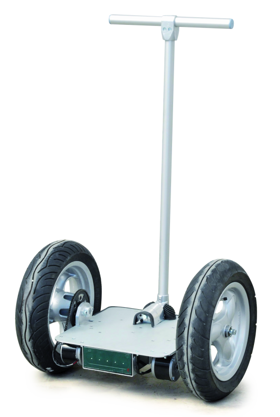
12″ x 2.75″
probably from a Kymco scooter (Gran Dink)
Boris, will you release the PCB schematic/board?
Any future plan to incoporate motor encoders?
Can’t wait to build my OpenWheels
Thanks!
Hi, in the previous post we presented the schematics.
Probably we’ll sell the board
Boris, the board and even the rest of the stuff as a package would be nice to buy. Available anytime soon?
As for the schematic, can you please post a higher resolution version of the image because it’s too small to read…
Thanks.
Dave
Never mind….I managed to download the high res version using Save target as…
Hi Boris,
Can you give a timeframe when you would sell the board?
Can you tell whether the SMD components will be on the board?
Thanks!
[…] Learn More about OpenWheels FirmwarePosted 2 weeks ago […]
hello ! when are available schematic and PCB ???
Thanks
http://www.open-electronics.org/discover-openwheels-electronics-and-test-it/
Hi
Still no info on PCB?
http://www.open-electronics.org/tag/openwheels/
hello sir this very interesanate this project.
I’m from Colombia and do not speak English so I hinders this project
and really wanted to do
do not know how I have knowledge in electronics but not in programming and that part I do not understand in the schematic plan is not the description of the integrated u5 and u6 appears I wonder if you can help me thanks
U4÷U7: IRS2184S
[…] We used float type variables only when it was strictly necessary and we implemented a system interrupt to manage, with the right timing, the stabilization operations. We did not skimp on protection systems and diagnostic messaging because, as an open source project, it must be easy to manage. Despite the hardware has already been described in previous articles, a small but crucial detail remained suspended: the scale of the gyro. In the first tests we used the gyroscope with a scale of 30 °/sec – definitely the optimum value when Openwheels is moving – which, however, in some situations led to a reading overflow. LCD Settings The management of all user customizable parameters is made through the LCD display, which also performs the function of monitoring the main diagnostic values. LCD Encoding errors current sensor. Adjusting the PID Parameters in the firmware. Learn More about OpenWheels Firmware. […]
[…] Learn More about OpenWheels Firmware. During the months spent developing OpenWheels, we worked hard to achieve a firmware that was both functional and fast. […]
Any progress in making the board available for sale?
Next month we’ll present a new board ;-)
@boris_landoni buona sera Boris. Sono un abbonato alla rivista Elettronica In e sull’ultimo numero ho visto la nuova OpenWheels2.0., ci saranno novità sul progetto OpenWheels? Migliorie a meccanica ed elettronica?
Ciao, la scheda 2.0 potrà essere utilizzanta anche su openwheels, ma dal punto di vista meccanico non abbiamo previsto migliorie.
PS Prox volta in inglese ;-)