A device that makes Raspberry Pi suitable for industrial environments, an alternative to PLCs for automation control applications.
In the 206th issue of Elettronica In, we featured the first device in the Strato Pi line created by Sfera Labs: the Strato Pi Server. This product, designed for industrial environments and based on Raspberry Pi, features an RTC clock, a UPS functionality and a series of communication interfaces supporting a wide range of industrial automation systems. The Strato Pi servers and boards are conceived as middleware devices for the integration of complex automation systems, reading field data and making them available to the user through user-friendly, remotely accessible HMI interfaces. The ultimate objective of these system architectures is to enable remote control of automation systems. Sfera Labs has enriched its product catalogue introducing a new series of professional devices, that offer even more sophisticated “middleware” solutions suitable for both industrial and residential use. This new product line is the Iono Pi series which, similarly to Strato Pi, offers DIN Rail cases for all models.
The main difference between these two series lies in their application areas. Strato Pi mainly functions as a server for web applications or communicating through the LAN/WAN with the user or other control systems. The interface with field automation systems is mainly based on the RS485 bus. Iono Pi’s philosophy, on the other hand, focuses predominantly on the acquisition and direct control of sensors and actuators. This involves the possibility of reading analogue signals, the availability of relay outputs and the availability of 1-Wire, Weigand, RS485, Bluetooth, GSM and radio protocols support. Iono Pi represents, in the end, a product line ready to satisfy a vast degree of user requirements at a competitive price.

FIG. 1: IONO PI’s external connections example
All products in the Iono series consist of one Iono board in a DIN Rail enclosure, connected to a microcontroller or a Raspberry Pi board. The main products in this series are:
- Iono Pi: a product combining a Raspberry Pi microcomputer with the Iono board. Iono Pi is available with or without RTC.
- Iono Arduino: a solution interfacing Arduino Uno Rev. 3, Arduino Zero, Arduino Yún Rev 2 boards, as well as other compatible options.
- Iono MKR: interfacing Arduino MKR boards.
- IonoPy: a solution that is compatible with all Pycom platforms such as WiPy, LoPy4, etc., which can be programmed through MicroPython.
- Iono Pi Touch: a module including a 7” display, featuring a robust and elegant aluminium case, suitable for industrial and residential use.
The solution outlined in this article is the version of Iono Pi with RTC. It consists of an Iono RTC board and a Raspberry Pi microcomputer enclosed in a 4 module DIN-Rail Case. Iono Pi is an I/O module that is extremely versatile, offering a variety of input and output sources, four power relay outputs and support for interfaces that are standard to modern PLC systems such as 1-Wire and Wiegand. A 2.5 A and 5 V voltage regulator accept input voltages between 9 and 28 V DC. The RTC version contains the Real-Time Clock circuit, along with its lithium backup battery. The Iono Pi RTC has a range of use cases that spans from data acquisition to automation system control, hotel room control, environmental control, and many others, on a both residential and professional scale. The Iono Pi module guarantees full software compatibility with the Raspberry Pi platform. A rapidly expanding library of frameworks and applications dedicated to Sfera Labs products facilitates the development of application solutions based on these modules.
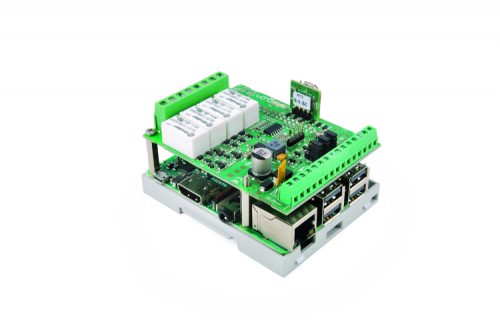
FIG. 2: IONO PI RTC board
External Connections
Iono Pi RTC contains two lines of terminal blocks, as seen in Figures 1 and 2, in addition to the eight output connectors to the power relays. These connectors are suitable for conductors with cross-section up to 2.5 mm2. The bottom section of the module consists of a line with 15 terminal blocks, dedicated to the power supply and all low voltage inputs and outputs, suitable for conductors with cross-section between 0.5 and 1.5 mm2. An overview of all the terminal blocks connections is illustrated in the diagram in Figure 3. The connections labels are also engraved on the DIN Rail case. Thanks to dedicated fixtures on the container, the other Raspberry Pi board external connections, i.e. the Ethernet, USB, HDMI, Audio/Video and power supply, can also be accessed.

FIG. 3: THE IONO PI CIRCUIT BOARD
RASPBERRY PI GPIO’s CORRESPONDENCE
Table 1 shows the mapping of the inputs and outputs of the Iono Pi module into the related pins of the Raspberry Pi board. These pins should not be used for other functions.
INSTALLING THE BOARD
The Iono Pi boards are provided with pre-installed connectors, eliminating the need for soldering. To install the Raspberry Pi board, simply align the connector on the board to the corresponding GPIO and connect the two after having verified that the two pins are perfectly in line. This procedure must be executed while the unit is not attached to a power supply. The usage of appropriate turrets/spacers to firmly bolt the two boards together, ensuring that no conductive part of one board touches any part of the other board, is recommended.
For the Server versions, a micro SD card with the operating system can be inserted using the dedicated fixture in the enclosure, using a paper clip or the tip of a ballpoint pen; there is no need to open the external box.
POWER SUPPLY
After the installation, it is strictly forbidden to power the Raspberry Pi from the micro USB port when it is powered from the Iono Pi board. If the Iono Pi is installed but the Raspberry Pi is not being powered, the micro USB can be connected, which could be an efficient solution during the installation and software configuration phases. An overview of the terminal block connections on the Iono Pi board can be found in Figure 3. The power supply inputs are identified with VCC. Suitable power supplies units should be able to provide voltages between 9 V and 28 V and power at least 15W. Do not reverse polarity. The power supply circuit implements reverse polarity and surges protection thanks to the SM6T transil and a 220 uF electrolytic capacitor. A blue onboard LED, visible through the front panel of the DIN-rail case, is lit when the unit is powered.
AUXILIARY VOLTAGE OUTPUTS
Iono Pi has an auxiliary 5Vdc voltage output pin on the terminal block, labeled 5VOUT, to supply power to external 1-Wire devices or other low-power loads. Never exceed the maximum rated current of 50mA on this output.
Another auxiliary voltage output pin, labelled VSOUT, is also available on the terminal block. It is intended as the voltage source for small loads connected to the open collector (OC) outputs. Its minimum output voltage is approximately VS – 1V. The maximum rated current on this output should not exceed 300mA.
Aix: ANALOG INPUTS
One of the most significant features of the Iono Pi RTC is the two analogue inputs (AI1 and AI2) on the line of on the low voltage terminal block, along with additional 2 analogue inputs (AI3 and AI4) on the CN3 connector (Figure 4). The voltage input range is 0-30V. The MCP3204 4-channel 12-Bit A/D converter from Microchip represents a good compromise between resolution and sampling speed.
The input impedance is approximately 200kOhm.
For convenience, a separate analogue ground connection (A-GND) is available on the terminal block, next to AI1. A-GND should be used to connect the ground reference of the analogue input signals. Since the analogue inputs are not galvanically isolated from the Iono Pi’s power supply, the A-GND line must be kept at the same voltage level of the negative power supply line (VS-) and the GND connection on the terminal block. A-GND should never be used as the negative power supply line or as a common ground for any other purpose than the analogue inputs ground reference.
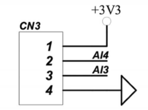
FIG. 4: ANALOG INPUTS EXPANSION HEADER (CN3)
Ox: RELAY OUTPUTS
Iono Pi has four single pole single throw power relays, with normally open contacts. The relays are driven by distinct GPIO lines on the Raspberry Pi, as indicated in Table 1.
TABLE 1: mapping of the inputs and outputs of the Iono Pi module into the related pins of the Raspberry Pi board
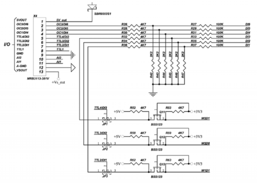
FIG. 5: TTL LEVEL CONVERTER CIRCUIT AND INPUT MODE SELECTION JUMPERS
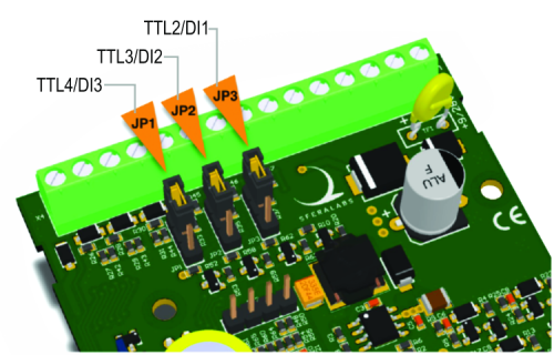
FIG. 6: INPUT MODE SELECTION JUMPERS POSITION
L1: On-board application LED
L1 is a green on-board LED that is controlled by the GPIO7 line on the Raspberry Pi.
Depending on the project specifications, it can be beneficial to set the level of the GPIO7 pin at the booting phase, using the appropriate command found in the /boot/config.txt file.
TTL1: 1-Wire input/output
TTL1 is a bidirectional TTL I/O line (0÷5V), connected to the Raspberry Pi GPIO4 pin through a bidirectional level shifter. It can be used as a 1-Wire bus line and can also serve as a generic TTL I/O or as the DATA0 line of a Wiegand interface.
The TTL1 front-end circuit has a 4.7kOhm pull-up resistor.
Voltages outside the 0-5V range should never be applied to this pin to avoid damage to the Iono Pi board and Raspberry Pi.
TTLx/DIx: TTL input/output or generic digital inputs
TTL2/DI1, TTL3/DI2 and TTL4/DI3 are dual-purpose pins as illustrated in Figure 5. Depending on the configuration of the corresponding internal jumpers (see Figure 6), they can function as they serve as TTL I/O lines or generic digital inputs. When TTL2/DI1 is configured as TTL I/O, it can be used as the DATA1 line of a Wiegand interface, in combination with TTL1, or any other generic TTL I/O function. When TTL3/DI2 is configured as TTL I/O, can be used as the DATA0 line of a second Wiegand interface, or any other generic TTL I/O function. When the TTL4/DI3 is configured as a TTL I/O, it can function as a DATA1 line for a second Wiegand connection, when combined with TTL3, or any other generic TTL I/O function
The TTL2-TTL4 front-end circuits have 4.7kOhm pull-up resistors.
When these pins are configured as generic digital inputs, they are protected by a resistor network, and pulled to ground when not connected. They accept positive voltage levels up to 40Vdc.
The DI1-DI3 front-end circuits have 2.2kOhm pull-down resistors.
OCx/DIx: Open collector outputs or generic digital inputs
OC1/DI4, OC2/DI5 and OC3/DI6 can be used as open collector (OC) outputs or generic digital inputs. They are connected to discrete open collector drivers with a maximum output current of 100mA. These outputs are individually protected against over-current and short circuits. When the over-current protection is triggered, the output will open, stopping the current flow. A simple reset to 0 of the corresponding Raspberry Pi’s GPIO pin will reset the protection. To drive a load using an OC output, connect its positive input to the VSOUT pin and the negative input to the OC pin. Note that the input resistors network is permanently connected to these pins so, even when the open collector driver is open (the corresponding Raspberry Pi’s GPIO pin is low), a small amount of current will still be able to flow to ground through an equivalent 6.9kOhm resistor. When not used as open collector outputs, the OC1/DI4, OC2/DI5 and OC3/DI6 can be used as generic digital inputs, like DI1-DI3. They are protected by a resistor network, pulled to ground when not connected, and accept positive voltage up to the VS power supply voltage. When used to detect the status of dry contacts, it is recommended to use VSOUT as the voltage reference. The DI4-DI6 front-end circuits have 2.2kOhm pull-down resistors.
Never apply voltage levels outside the specified operating limits to DI4, DI5 or DI6. Voltages above the power supply voltage (VS) will permanently damage the device and the Raspberry Pi board. Negative voltages may also cause device malfunction or damage.
RTC (Real Time Clock)
The heart of the RTC circuit is Microchip’s, MCP79410 (U10), an RTC chip of widespread use which incorporates a 64 byte SRAM memory with the BT1 back-up battery, 1K of EEPROM memory and 64 bit of write protected EEPROM memory, along with the standard time and calendar functions. The U10’s internal clock is regulated by the 32,768 Hz Y1 quartz. The 3.3 V power supply is sourced from the U8 DC/DC converter’s output. Communication with the Raspberry uses the I2C bus, where the Raspberry Pi acts as the master and the RTC chip as the slave. A BT1 lithium battery, CR1025 model, is used as a power supply for the RTC circuit when the main power is not available and during storage. Under operating conditions, where the board is continuously powered, the duration of the lithium battery can last up to 10 years.
SOFTWARE INSTALLATION
The utilities and libraries developed for Iono Pi are based on Linux. However, Iono Pi’s can be used with other operating systems supporting the Raspberry Pi.
The following instructions outline the software installation of the Iono Pi with the Raspbian operating system. The first step is to prepare a micro SD card on which this operating system is installed. The process of preparing such micro SD Card has been previously detailed many times in past articles and can be briefly summarized by the following steps:
- Download the Raspbian Stretch OS’ image in the Desktop version from the Raspberry Pi website;
- Unzip the image;
- Transfer the image onto the micro SD Card using either Etcher or Win32DiskImager;
- In the boot partition, write a blank file with the name “ssh” (no quotation marks);
- Insert the micro SD card into the appropriate slot on the Raspberry Pi;
- Connect a network cable to the Raspberry Pi’s Ethernet connector;
- Connect monitor, keyboard, and mouse;
- Switch on the Raspberry Pi;
- You can perform the configuration both using the graphic interface and the “Terminal” application;
- WiFi and Bluetooth can be disabled depending on the user preferences and requirements;
- Enter the Raspberry Pi configuration parameters, such as an IP address, monitor, RealVNC, etc.;
- IMPORTANT: the “Raspberry Pi Configurator” tool (located on the “Interfacing Options” menu), or the Raspi-config tool must be used to enable the I2C, SPI and 1-Wire buses;
- Reboot the system to activate the new configuration settings.
All the Iono Pi functions, except for the Real-Time Clock and the analogue converter, can be controlled from the Raspberry Pi’s GPIO pins. The Real-Time Clock requires the use of the I2C bus, whilst the ADC converter utilizes the SPI bus.
A series of utilities, in the form of shell commands for the control of the different functions, as described above, can be found on the Iono Pi manufacturer’s website.
Firstly, update the Raspberry Pi’s operating system by inputting the following commands:
apt-get update
apt-get upgrade
apt-get dist-upgrade
Then, install the “i2c-tools” pack, a tool that can be useful for testing of the I2C bus:
apt-get update
sudo apt-get install i2c-tools
Download and install the management utilities for the Iono Pi board (Figure 7).
sudo apt-get install git-core
git clone –recursive https://github.com/sfera-labs/iono-pi-c-lib.git
cd iono-pi-c-lib
sudo sh build
Perform a precautionary reboot of the system.
At this point, if the utilities are run without parameters, a “help” message will be displayed by the “help” utility, as seen in the code listing in Figure 8.
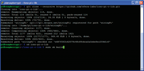
FIG. 7: INSTALLATION OF THE IONO PI UTILITY

FIG. 8: IONO PI HELP UTILITY
All commands must be run by the general user “pi”, using the “sudo” (superuser do) command which transfers some of the “root” user’s privileges to other authorized users.
For example:
To read the Iono utility’s version, enter:
sudo iono -v
In order to open or close relay 1, type:
sudo iono o1 close
sudo iono o1 open
To turn the green LED on and off, enter:
sudo iono led on
sudo iono led off
The DS18B20 temperature sensor, connected to the 1-wire bus, is depicted in Figure 9. To read the temperature of the 28-xxxxx 1-Wire sensor, its ID must first be identified:
sudo iono 1wire bus
Only then can the temperature be read (as seen in Figure 10):
sudo iono 1wire bus idxxxxx

FIG. 9: IONO PI CONNECTED TO A TEMPERATURE SENSOR, 1-WIRE
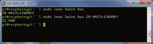
FIG. 10: TEMPERATURE READING FROM A 1-WIRE SENSOR
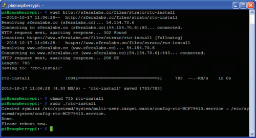
FIG. 11: Installing the Real Time Clock software

FIG. 12: DEVICES DETECTION ON THE I2C BUS
RTC MANAGEMENT SOFTWARE
Install the management utility for the RTC function as seen in Figure 11:
Cd /
wget http://sferalabs.cc/files/strato/rtc-install
chmod 755 rtc-install
sudo ./rtc-install
If no errors are displayed, delete the installation script and run a new reboot:
rm rtc-install
sudo reboot
Check that the Raspberry Pi can correctly “see” the RTC clock on the I2C bus. To test it, enter the following two commands:
sudo modprobe -r rtc_ds1307
i2cdetect -y 1
The output depicted in Figure 12 should be displayed.
At the 6f address, the “6f” characters corresponding to the RTC clock’s I2C address should be visible. An undetected clock can be the result of an incorrect software installation. This can be verified by entering the following command:
Lsmod
(list modules) will show if the “i2c_dev” and the “i2c_bcm2708” modules are present. Once the RTC clock is correctly installed and functional, the date and time will automatically be updated; this can be double-checked against the standard date and time management commands in the GNU/Linux environment.
To verify the correct operation of the RTC function, after having ensured that the Raspberry Pi is connected to the internet, follow the procedure detailed below. Please note that this was already a necessary condition for completing the previous steps.
Firstly, check the system date and time with the following command:
Date
The “date” command displays the system’s date and time which should have been updated automatically when the operating system booted, via direct access to one of the internet serves to provide the “NTP” service (network time protocol). Figure 13 illustrates a possible result.
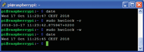
FIG. 13: RTC SETTINGS AND CONTROLS
Now, verify the date and time memorized in the Iono Pi board’s RTC clock using the command:
sudo hwclock -r
Figure 12 displays a possible result. If the date and time returned are incorrect, or if an error message is displayed, update the RTC clock with the system time by inputting:
sudo hwclock -w
The “-w” parameter launches the operation in charge the of writing the date and time in the RTC clock. Now, execute the previous test once again and verify if the two clocks are now synchronized
FROM OPENSTORE
IONOPI_RTC MODULE I/O PI WITH RTC

[…] Read the article here […]