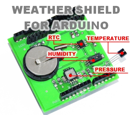
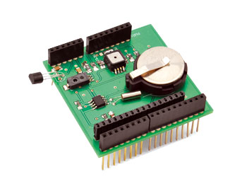
There are many shields available almost for every application. Today we want to show you how to use your Arduino as a wheater station which can be improved, unlike commercial products that cannot be expanded or easily modified. Our shield uses three analog sensors in order to measure enviromental temperature, relative humidity and atmosferic pressure. As an extra feature we added a RTC, based on the famous DS1307 ic made by Maxim.
The used sensors are:
-Microchip MCP9700A for the temperature;
–Honeywell HIH-5030-001 for the relative umidity;
-Freescale MPXH6115A6U for the absolute pressure.
SCHEMATIC
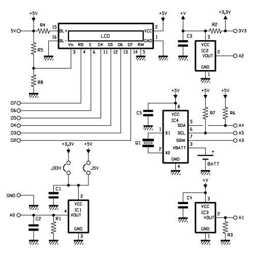
The analog pins used are A0 (pressure), A1 (humidity) and A2 (temperature).
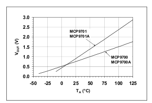 MCP9700A should be used in the voltage range 2.3-5.5V, it has a linear transduction characteristic (10mV/°C) with an output of 500mV@0°C (see figure) not require any calibration: the manufacturer guarantees an accuracy of +/-2°C in the full operating range (-40÷125°C) and +/-1°C in the commercial temperature range (0÷70°C). We selected the TO92 package version and located the component near the PCB edge in order to have more flexibility in case somebody needs to measure the temperature of objects. C3 is the usual 100nF bypass ceramic capacitor; the 220Ω R2 resistor reduces the output noise.
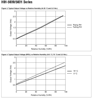
HIH-5030-001 should work in the range 2.7-5.5V; the ouput is proportional to the umidity as reported by the following relation: VOUT=(VSUPPLY) [0.00636 (sensor RH) + 0.1515 (typic value @25°C). The accuracy is +/-3% in the range 11-89%. The relation between Vout and RH is linear with a negligible histeresys (@25°C), as visbile in figure which shows also a narrow deviation of the transduction characteristic in the range 0-70°C. A 100KΩ resistor as been added to the output as required by the datasheet.
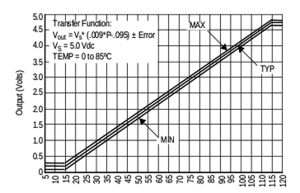 MPXH6115A6U requires 5V to work; its accuracy is +/-1.5% of Full Scale Span (VFSS is defined as the algebraic difference between the output voltage at full rated pressure and the output voltage at the minimum rated pressure). As the previous components, the linearization has performed by the transducer itself and no offset correction or settings are required. There are pressure transducers which require 3.3V (e.g. MP3H6115A) therefore on the PCB there are two voltage selector jumpers (J3.3V and J5V) to select the appropriate voltage. For the temperature and humidity transducers we have chosen 3.3V as working voltage.
NOTE: FOR ARDUINO DUE MUST BE USED 3.3V SENSORS ONLY IN ORDER TO AVOID DAMAGES TO THE DUE.
The RTC schematic section is the one in the datasheet with the 32.768 Khz quartz and the two I2C 1K pull-up resistors R6 and R7. The auxiliary clock SQW output is available at A3 for future needs.
BOM
[code]
R1: 51 kohm (0805)
R2: 220 ohm (0805)
R3: 100 kohm (0805)
R4: 100 ohm (0805)
R5: 1 kohm (0805)
R6: 1 kohm (0805)
R7: 1 kohm (0805)
R8: 22 ohm (0805)
C1: 100 nF
C2: 47 pF
C3: 100 nF
C4: 100 nF
C5: 100 nF
IC1: MPXH6115A6U
IC2: MCP9700A
IC3: HIH-5030-001
IC4: DS1307SO8
Q1: 32768 kHz
LCD: Display LCD 16×2
[/code]
SKETCH
The libraries necessary are three:
–Wire.h and RTClib.h are required by I2C and DS1307 data communication with Arduino;
–LiquidCrystal.h is required for data visualization on a 16X2 LCD display.
As usual “LiquidCrystal lcd(7, 6, 5, 4, 3, 2);” is necessary to tell to Arduino which are the phisical connection with the LCD; “define TEMP 2”, “define UMID 1”, “define PRESS 0” give information to the Arduino board about sensors and their connections to the ADC pins.
“byte degree[8] = { //
B10111,
B01000,
B10000,
B10000,
B10000,
B01000,
B00111,
};”
has been used to create the character “°C” togheter with “lcd.createChar(0, degree);“ and “lcd.write((uint8_t)0);” as detailed in the Arduino’s “Reference” page.
NOTE:
“lcd.write((uint8_t)0);” is the code for IDE 1.X; for previous IDE version use “lcd.createChar(0, degree);”.
The other code lines are used to send RTC and sensors data to LCD and to the serial port; before the value is displayed, the average value of 100 samples is calculated for analog data coming from each sensor in order to reduce noise and fluctuations, working as a low pass filter.
The sensors used do not require any calibration or adjustment anyway it is possible to increase the accuracy by adding a correction value: “TCORR”, “RHCORR”, “PCORR”. If necessary, these values have to be defined by comparison with other sensors e.g. with a commercial weather station which have a higher accuracy.
The pressure measured by barometers is the relative atmospheric pressure but the one coming from our sensor is the absolute atmospheric pressure. Atmospheric pressure is related to the altitude and this relation is used by many commercial altimeters which are barometric instruments. Relative atmospheric pressure is measured at sea level. A easy way to have relative atmospheric pressure from absolute atmospheric pressure is to add a constant (DPR in our code) which is the difference between the value displayed by a commercial weather station and our shield.

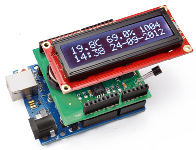
The combination of our shield and the solar shield made by Seeedstudio is a complete stand alone weather station which can be used everywhere, requiring only a solar panel to recharge a lithium battery used to power the whole system.
//CODE WRITTEN BY HARDWARE MAKERS www.hwmakers.eu

// RTC LIBRAY AND RELATED CODE HAVE BEEN WRITTEN BY OPEN ELECTRONICS http://www.open-electronics.org/

// required libraries
#include <Wire.h>
#include "RTClib.h"
#include <LiquidCrystal.h>

LiquidCrystal lcd(7, 6, 5, 4, 3, 2);

RTC_DS1307 RTC;

// VARIABLES DEFINITION AND INITIALIZATION

#define TEMP 2      //TEMPERATURE ACQUISITION ON ANALOG PIN 2
#define UMID 1      //HUMIDITY ACQUISITION ON ANALOG PIN 1
#define PRESS 0     //PRESSURE ACQUISITION ON ANALOG PIN 0
float val = 0.0;
float T= 0.0;
double umidita = 0.0;
double RH = 0.0;
double RHout = 0.0;
double UM = 0.0;
double Pascal=0.0;
double PS=0.0;
double P=0.0;
float VADC= 5;
int DPR = 0;
int RHCORR = 0;
int PCORR = 0;
int TCORR= 0;
double STAMPA_T = 0;
double STAMPA_U = 0;
double STAMPA_P = 0 ;
byte degree[8] = { //  CHARACTER "°C" DEFINITION
  B10111,
  B01000,
  B10000,
  B10000,
  B10000,
  B01000,
  B00111,
};

void setup() {
  Serial.begin(9600);
  lcd.begin(16, 2);
  lcd.createChar(0, degree); // "°C" SYMBOL
  Wire.begin();
  RTC.begin();
  RTC.sqw(1);		//0 Led off - 1 Freq 1Hz - 2 Freq 4096kHz - 3 Freq 8192kHz - 4 Freq 32768kHz

  if (! RTC.isrunning()) {
    Serial.println("RTC is NOT running!");
    // following line sets the RTC to the date & time this sketch was compiled
    RTC.adjust(DateTime(__DATE__, __TIME__));
  }
}

void loop() {

  // RTC LCD OUTPUT

  DateTime now = RTC.now();
  lcd.setCursor(0, 1);
  if (now.hour() < 10) {
    lcd.print("0");
  }
  lcd.print(now.hour(),DEC);    // HOUR
  lcd.print(":");
  if (now.minute() < 10) {
    lcd.print("0");
  }
  lcd.print(now.minute(), DEC);// MINUTES

  lcd.setCursor(6, 1);
  if (now.day() < 10) {
    lcd.print("0");
  }
  lcd.print(now.day(), DEC);  // DAY
  lcd.print('-');
  if (now.month ()<10) {
    lcd.print("0");
  }
  lcd.print(now.month(), DEC);//MONTH
  lcd.print('-');
  lcd.print(now.year(), DEC);  //YEAR

  // SERIAL RTC OUPUT

  if (now.hour() < 10) {
    Serial.print("0");
  }
  Serial.print(now.hour(),DEC);
  Serial.print(":");
  if (now.minute() < 10) {
    Serial.print("0");
  }
  Serial.print(now.minute(), DEC);
  Serial.print(":");
  if (now.second() < 10) {
    Serial.print("0");
  }
  Serial.print(now.second(), DEC);
  Serial.print("; ");

  if (now.day() < 10) {
    Serial.print("0");
  }
  Serial.print(now.day(), DEC);
  Serial.print('-');
  if (now.month ()<10) {
    Serial.print("0");
  }
  Serial.print(now.month(), DEC);
  Serial.print('-');
  Serial.println(now.year(), DEC);

  Serial.println();

  // SERIAL METEO OUTPUT

  STAMPA_T= (temp());
  STAMPA_U= (readUMID());
  STAMPA_P = (pressure());

  Serial.print("TEMPERATURA ");
  Serial.print(STAMPA_T);
  Serial.write(176);
  Serial.print("C; ");

  Serial.print("UMIDITA' ");
  Serial.print(STAMPA_U);
  Serial.print("%; ");

  Serial.print("PRESSIONE ");
  Serial.print(STAMPA_P);
  Serial.println("mbar");

  // LCD METEO OUTPUT

  lcd.setCursor(0, 0);
  lcd.print(STAMPA_T,1); //SHOW ONLY THE FIRST DECIMAL
  lcd.write((uint8_t)0); //PRINT "°C" CHARACTER (IDE 1.0.1)
  delay(200);

  lcd.setCursor(6, 0);
  lcd.print(STAMPA_U,1);//SHOW ONLY THE FIRST DECIMAL
  lcd.setCursor(10,0);
  lcd.print("%");
  delay(200);

  lcd.setCursor(12, 0);
  lcd.print(STAMPA_P,0);//SHOW ONLY THE INTEGER PART
  delay(200);
}

float temp() {
  double nread = 100.0;          // NUMBER OF READINGS
  double somma = 0.0;
  for (int i=0; i<nread; i++)
  {
    val = analogRead(TEMP);
    T = (((VADC/1024.0*val)-0.5)* 100)+TCORR;   //TEMPERATURE
    somma += T;
  }
  delay(100);
  return (somma/nread);
}

double readUMID(){
  double nread = 100.0;          // NUMBER OF READINGS
  double somma = 0.0;
  for (int i=0; i<nread; i++)
  {
    UM = analogRead( UMID );
    RHout=(((UM*VADC/1024.0/3.3)-0.1515)/0.00636)+RHCORR;    //HUMIDITY
    somma += RHout;
  }
  delay(100);
  return  ( somma / nread );
}

float pressure(){
  double nread = 100.0;           // NUMBER OF READINGS
  double somma = 0.0;
  for (int i=0; i<nread; i++)
  {
    Pascal=analogRead(PRESS);
    P=(((Pascal*VADC/1024)/VADC+0.095)/0.009)*10+DPR+PCORR;  //PRESSURE TRANSFERT FUNCTION
    somma += P;
  }
  delay(100);
  return  ( somma / nread );
}

Wow! Here’s another copy – translate – paste of this article: http://www.sawers.com.bo/blog/2013/03/metereologica/
eliminate the LCD and add a logger SD. Can the system be used to sample the sensors three times a day for about 4 months with periods of about a week without sun? What if the supply is 4 ea AA rechargeables (about 2400ma-hrs)
[…] Weather shield […]
[…] that takes the form of a Arduino-based weather station, by adding a Weather Shield presented in this post and a very simple cyclic timer, which is also implemented as a shield: our stack will therefore be […]