- Building a 3D Digital Clock with ArduinoPosted 4 months ago
- Creating a controller for Minecraft with realistic body movements using ArduinoPosted 5 months ago
- Snowflake with ArduinoPosted 5 months ago
- Holographic Christmas TreePosted 6 months ago
- Segstick: Build Your Own Self-Balancing Vehicle in Just 2 Days with ArduinoPosted 6 months ago
- ZSWatch: An Open-Source Smartwatch Project Based on the Zephyr Operating SystemPosted 7 months ago
- What is IoT and which devices to usePosted 7 months ago
- Maker Faire Rome Unveils Thrilling “Padel Smash Future” Pavilion for Sports EnthusiastsPosted 8 months ago
- Make your curtains smartPosted 8 months ago
- Configuring an ESP8266 for Battery PowerPosted 8 months ago
An Easy and Customizable Arduino powered Weather Station connected with Xively

Use Arduino as a Xively HTTP client and interact with the new shield for power management.
We already talked about WiFi connectivity for Arduino in other posts, presenting the design of a high performance WiFi shield and explaining how to use it both as a web server, or a web client. The two modes of operation enable to a wide range of applications supported by network connectivity. Unlike other shield, ours incorporates a module that is able to take over those tasks which, if left to the Arduino, prevent it from carrying out its work with reasonable responsiveness, precluding thus the possibility to implement many of the applications envisioned. In other words, our WiFi shield handles all the HTTP protocol, meaning that it allows the Arduino to focus on the role of client/server, forgetting managing web connections.
Today, based on the Arduino and the WiFi shield, we will propose an application that takes the form of a Arduino-based weather station, by adding a Weather Shield presented in this post and a very simple cyclic timer, which is also implemented as a shield: our stack will therefore be composed of an Arduino , the WiFi shield, the weather shield and the timer shield.
We already know the first two elements, then we will explain the others. But before that, it’s important to anticipate what is the purpose of our project: this is a web application that can detect climatic data and publish them on the website www.xively.com.
The Xively website
Xively website was born to serve “the Internet of things” and is a virtual cloud space, dedicated to the collection and sharing of data collected from disparate sensors. It allows free use, in the form of “development accounts”, to allow potential users to test the functionality provided. If you want to use this site for amateurial purposes and realize the application described here, you must register a “Free Developer Account” by entering a few essential information.

At this point it comes to defining the source of your data; or what is called generically “device”. This data source is also called feed and it has an identification number (Feed Id), a reference URL and a URL to use with the connection APIs. It also has a long KEYWORD to be used to enter and manage data. Everything is automatically defined when you create a device. A device can have several channels (datastreams), each of which corresponds to a type of measurement (temperature, pressure, etc..). So, after you have defined your devices, you have to create at least one channel, which will be identified by its name (eg temperature).
Once defined the destination of your data, it comes to deciding which mode to use for connections. In fact, you can use the http protocol but also the connection using sockets. For the sake of simplicity we will use the Web access.
To send the data you must make a “request” with “PUT” method. The call should be forwarded to “api.xively.com”, and more specifically to the resource “/v2/feeds/yourfeedid” But we must also define, in the http package, the following header:
- Host: api.xively.com
- X-apikey: 39KvFo30fuhM … (abbreviated here)
You can also route the call to the site “api.xively.com” using the corresponding numerical address “173.203.98.29”, rather than the url, in case of DNS issues. The data can be provided in different formats: XML, JSON, CSV. We have chosen, for simplicity, the CSV format (Comma Separated Values). Then, having to publish meteorological data you can to provide three lines such as:
temperature, 19
Pressure, 1022
Humidity, 62
You can display the collected data in the form of a graph directly on the site. But there are several possible other display modes.

The site also provides libraries for the most popular systems and therefore also for Arduino; but of course the library provided refers to basic Arduino WiFi and therefore is not usable in our case.
By the way, thanks to the simplicity of our library in dealing with the HTTP protocol, the code needed is just made of a few lines.
Arduino as an HTTP client
To use our WiFi shield, we proposed a special library. The author of the library keeps updating it from time to time and is now available, improved and updated, in 2.4 version. Lately the Client mode (sendRequest) was enhanced with the possibility to define the HTTP header, so as to allow the connection with servers that require the presence of particular headers. Also PUT and DELETE methods were added, provided by the REST (Representational State Transfer) approach. In server mode (getRequest), on the other hand, authentication has been added.
In the examples we provided with our library you already have an Arduino sketch to create an HTTP client that communicates with a custom server. Now, with the aim of illustrating the ability to connect to a public server, we explore better use the library as a client, referring to the next article deepening of the server mode. Here are the steps to be taken.
- Connect to the WiFi router.
- Connect to the IP address of the server (with a certain port).
- Make the string with the data to send.
- Define the resource address on the server.
- Define the method to use (GET, POST, PUT, DELETE).
- Define headers.
- Send (sendRequest) providing method, resource, header and data (if using POST or PUT).
8 .Await response (getResponse) and we use (if we used GET).
- Close the socket with the server.
Applying this in with Xively, we have, in this case, the following series of statement.
- WIFI.ConnectWPAwithKey(ACCESSPOINT,key);
- csocket=WIFI.openSockTCP(REMOTEIP,PORT);
- snprintf_P(recValues,64,FVal,stemp,sumid,spress) ;
- #define RESOURCE “/v2/feeds/1070345129.csv”
- the method used is PUT
- #define HOST “Host: api.xively.com”
#define KEY “X-ApiKey: 39KvFo30fu…”
- WIFI.sendRequestPUT(csocket,headers,2,RESOURCE,recValues);
- WIFI.getResponse(csocket,1000); (1s timeout)
- WIFI.closeSock(csocket);
The connection to Xively is made in one step and exploits the key that has been drafted for the one-time WiFi router used. The key is drawn as a function of the password and once calculated, can be used for almost immediate access. Instead password access may take up to a minute due to the calculation of the key. Obviously the key was previously stored. In this application, which provides for periodic Arduino shutdowns (see below), the key is stored in the EEPROM.
Regarding the connection to the server there’s not much to add compared to what is said in the post that introduced the library. The socket number (CSocket) must be less than 255 because to mean a connected socket.
The construction of the data-string was done using an AVR C function which allows the use of format in the program memory, so as to economize on the RAM. fact, that of RAM scarcity ( 2k on Arduino Uno), is one of the major problems that needs to be addressed when making complex programs on these versions of Arduino. For this reason the library itself makes extensive use of program memory for string literals and text messages.
On the definition of the resource to be addressed on the method and on the necessary header, there is not much to say besides the fact that they are those indicated by Xively.
As mentioned above, the modes sendRequestPUT sendRequestDELETE were added to the library possible to cope with the requirements of public servers.
A timeout was added to the getResponse, so to be sure of the arrival of the response.
Consumption management
The application proposed here provides for the periodic delivery of meteorological data collected by the Weather shield; it comes to temperature, barometric pressure and humidity. Furthermore than the sensors, the shield also sports a RTC (Real Time Clock) made with the Maxim DS1307 IC.
With the Weather Shield, we implement a real weather station even better than the commercial ones, because our platform is expandable and configurable by changing the code and adding additional devices and shields (as in our case where we add internet connectivity through a WiFi shield). The sensors mounted in the Weather shield are:
– MCP9700A for measuring temperature
-HIH-5030-001 of Honeywell, to determine the relative humidity
-MPXH6115A6U from Freescale to provide data regarding the absolute atmospheric pressure.
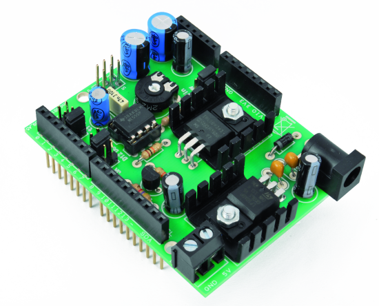
Weather data taken from the system, typically are acquired at intervals of several minutes or even hours. For this reason, it makes no sense to keep system on, let alone the Weather shield, all the time. Leave all continuously fed means consuming more than one hundred milliamps / hour (between WiFi and Arduino shield) to use it for about 4 seconds (this is the time it takes to upload the data on Xively) every 10 minutes – or even hourly – a waste of power. Saving power becomes vital if the system is battery powered and connected only to WiFi. That’s the reason why we decided to design a shield with very elementary power management, whose task is to turn the system on only when used, and turn it off when not. This shield has a variable power input adjusted to from 7 to 15 Vt and a direct input at 5 V. The power supply takes place via this Arduino shield that provides the voltage on its pin 5 V.

The shield is essentially a cyclic timer based on the classic 555 monostable configuration, which controls a MOSFET as electronic switch used to turn on and turn off Arduino at intervals dictated by the time of charging and discharging of a timing capacitor; the circuit feeds the 5V contact of Arduino while charging the capacitor, which occurs in a very short time, when compared to that of discharge (when the MOSFET is interdit).
Once on the system is on, the Arduino performs the operations and then goes to sleep, placing high logic level on contact 8: this interrupts the power supply to the timer for a period established by the RC group of 555.
As the Weather shield also contains an RTC (DS1307) (with battery backup) we decided to wake the Arduino every minute for it to quickly check if it is time has passed (every 10 minutes). In case not, the system goes back to sleep. In this way you keep a resolution to the minute without having to rely on long and imprecise charging time of the capacitor. The time required for the control is very low and in any case does not turn on the WiFi, so consumption is negligible.
When the wait time established, Arduino connects and transmits data. All this happens in about 4 seconds. The consumption so low that allows us to feed the system even with a small solar panel with a battery.
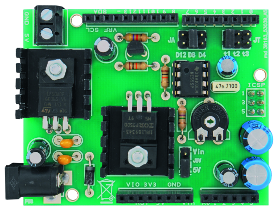
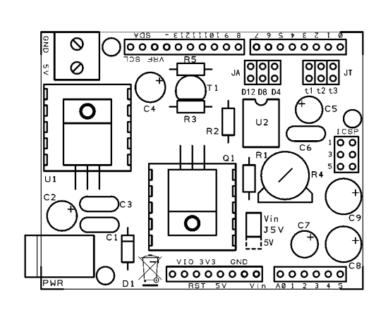
As you can see from the diagram, the shield has a feed section and another for the management of the 5 V pin of the Arduino. The power supply section allows to supply a voltage ranging from 4.5 V up to 15 V. In fact, if we wanted to feed Arduino with three AA batteries for a total of 4.5 V or finally, four AA batteries (NiCd or NiMH) for a total of 4.8 V, this can be done through the direct 5V connector that is connected to the 5V Arduino contact (Arduino can also be operated at voltages below 5 volts). The same is true if we wanted food source Arduino with a standard USB 5V.
If we wanted to feed the Arduino with a 6V battery (and up 15V) we could do this by using the power connector connected to U2 (LF50AB) which is a low droput regulator (450mV) and low load current (<1mA) and with a maximum load of 1A.
D1 input diode is only for protection and it’s better to short-circuit it in the case of 6 volts supply. So, with this board we “bypass” the standard Arduino power to gain a a greater freedom of sources.
The power management section, however, takes care of close it on command. The command is provided from one of the digital I/O pins D4, D8, D12 of Arduino brought to a high level; the pin is chosen by the JA jumper on the basis of what line is available and implemented in the sketch. In practice, if one of the D4, D8, D12 is busy, set JA to use a free line and modify the sketch accordingly.
In the instant the classic 555 (U3) circuit receives this pulse via T1, which operates as a separating (and inverting) interface, its pin 3 (out) goes high and doesn’t provide anymore the most negative value to the gate of P-channel Q1 MOSFET. MOSFET IRLIB9343, which has a low response threshold (about-3V), interrupts then the power to the 5V pin of the Arduino.
Circuit 555 operates in monostable mode and puts up its output as soon as it receives the trigger pulse: it charges the capacitor through R1 and R2 trimmer. Once the threshold value is reached, the 555 discharges the capacitor and returns to the initial state with low output, for which Q1 returns to conduct.
The time during which the power of Arduino is interrupted is defined by the formula:
Where T is expressed in seconds. Since R is a total of about 5.4 Mohm (halfway trimmer), we have prepared three different capacitance values can be managed via the jumper, allowing as many intervals:
- 10 uF for a time T of 60 seconds
- for a 100 uF T time of 10 minutes,
- 600 uF for a time T of 3.600 s (1 h.)
The Arduino sketch
#include <avr/sleep.h>
#include <avr/power.h>
#include <avr/interrupt.h>
#include <avr/wdt.h>

#include <HTTPlib.h>             // include library
#include <EEPROM.h>
#include <Wire.h>
#include "RTClib.h"
/*********************************************************************/

#define ACCESSPOINT  "D-Link-casa"       // access point name
#define PASSWORD     "pwd"          // password if WAP
#define REMOTEIP     "173.203.98.29"     // xively computer address
//#define REMOTEIP     "api.xively.com"  // xively computer address
//#define REMOTEIP     "192.168.1.2"     // test computer address
#define PORT         80                  // application port

#define RESOURCE     "/v2/feeds/1070xxxx9.csv"
#define KEY          "X-ApiKey: xxxxxxxxxxxxxxxxxxxxxxxxxxxxxxxxxxxxxxxxxxxxx"
#define HOST         "Host: api.xively.com"

#define TIMEINT      10                  // time interval in minutes
                                         // allowed values: 10,15,30,60

#define PINPOWER     8                   // pin linked with power management shield
#define PINEEPROM    12                  // pin to rewrite EEPROM

#define TEMP 2      //TEMPERATURE ACQUISITION ON ANALOG PIN 2
#define UMID 1      //HUMIDITY ACQUISITION ON ANALOG PIN 1
#define PRESS 0     //PRESSURE ACQUISITION ON ANALOG PIN 0

/*********************************************************************/
#define VADC 4.48
#define DPR 0
#define RHCORR 0
#define PCORR 0
#define TCORR 0 //modificato bias 8 gradi
/*********************************************************************/
#define Lpb 64

prog_char NoRTC[] PROGMEM="No RTC-Meteo shield; abort!";
prog_char NoAccP[] PROGMEM="Access point %s out of reach; abort!";
prog_char NoCKey[] PROGMEM="No connection to %s with key";
prog_char NoCPsw[] PROGMEM="No connection to %s with password";
prog_char NoSck[] PROGMEM="No connection socket to %s on port %d";
prog_char AvAccP[] PROGMEM="Access point available:";
prog_char Str[] PROGMEM="Start...";
prog_char IsKey[] PROGMEM="Key in EEPROM";
prog_char NoKey[] PROGMEM="No key in EEPROM";
prog_char NewK[] PROGMEM="New key activated";
prog_char Disc[] PROGMEM="Disconnected!";
prog_char Spw[] PROGMEM="Switching off or saving power...";
prog_char IntEl[] PROGMEM="Interval elapsed: %s %%";
prog_char AccP[] PROGMEM="Net connected with access point: ";
prog_char Sconn[] PROGMEM="Connesso con: %s port %s";
prog_char Sent[] PROGMEM="Sent to %s  :";
prog_char Scls[] PROGMEM="Socket closed!";

prog_char FVal[] PROGMEM="Temperature, %s\r\nHumidity, %s\r\nPressure, %s";
prog_char FTst[] PROGMEM="%4d-%02d-%02d %02d:%02d:%02d";

char pbuff[Lpb+1];
/*********************************************************************/
#define VERBOSE 0              // if 0 display log message only for error
                               // if 1 display log message for each step
                               // if 2 display log message for each suspension too

char ip[16];                   // buffer for local ip address
boolean fw=0;                  // flag WIFI
int fc=0;                      // flag connection
boolean fs=0;                  // flag socket open
int csocket;                   // client socket handle

HTTP WIFI;                     // instance of MWiFi library

byte key[32];                  // key buffer on ram
boolean fkey;                  // buffer of EEPROM(0) flag . It means key in memory

RTC_DS1307 RTC;                // RTC instance
DateTime now;                  // Date structure
char TimeStamp[25];            // timestamp string YYYY-MM-DD hh:mm:ss

char recValues[65]="\0";       // sensors value buffer to send data
/***********************************************************************/

void setup()
{
    pinMode(PINEEPROM,INPUT_PULLUP);                      // setup pin for EEPROM rewriting
    digitalWrite(PINPOWER,LOW);
    pinMode(PINPOWER,OUTPUT);                             // setup pin for power off
    Serial.begin(9600);                                   // Serial communication for error log
    if (VERBOSE) printMess(Str);

    if (EEPROM.read(0)==1)                                // If EEPROM key flag is OK then reads key stored
      {fkey=true; int i;for(i=0;i<32;i++) key[i]=EEPROM.read(i+1);
        if (VERBOSE) printMess(IsKey);}
    else
      {fkey=false;                                        // else uses password
        if (VERBOSE) printMess(NoKey);}

    if (digitalRead(PINEEPROM)==LOW)                      // be carefull! Just one shot .
     {fkey=false; if (VERBOSE) printMess(NewK);}          // Don't let low (to GND) the PINEEPROM,
                                                          // otherwise EEPROM will be rewrite each time!

    setupRTC();                                           // startup RTC shield

    if (!verifyRTC()) switchOff();                        // if RTC shield is not here switch off!

    getDate(TimeStamp);                                   // get time

    if (!checkTimer()) switchOff();                       // if interval is not expired switch off (suspension).
    if (VERBOSE) Serial.println(TimeStamp);               // else continue

    WIFI.begin(); fw=true;                                // startup wifi shield

    if (!verifyAccessPoint()) switchOff();                // if accesspoint is not availlable switch off!

    if (!netConnection()) switchOff();                    // if can't connect to access point switch off!

    if (!socketConnection()) switchOff();                 // if can't connect to server switch off!

    sendData();                                           // if everything is OK send data

    switchOff();                                          // end of task
}

/****************************** Routines ***********************************/

/* It switches off Arduino for the time defined on power management shield (typically 1m), */
/* or puts Arduino in power-down mode, if power management shield is not used.             */
void switchOff()
{
    if (fs) {WIFI.closeSock(csocket);fs=false;}
    if (fc) {WIFI.Disconnect();fc=0;if (VERBOSE) printMess(Disc);}
    delay(400);
    if (fw) WIFI.setPowerOff();
    delay(100);
    digitalWrite(PINPOWER,HIGH);                         // powered off (end program)
    // not reacheable if power management is used
    // just in case of alwais powered-on system, next routine will be used for power reducing
    if (VERBOSE) {printMess(Spw);delay(100);}
    savePower();
}

boolean verifyRTC()
{
    if (! RTC.isrunning())
     {
       printMess(NoRTC);
       int i;for (i=0;i<240;i++) {WIFI.setLed(3,i%2);delay(250);}
       return false;
     }
    else return true;
}

boolean checkTimer()
{
    int ss=now.minute()*60;
    int ts;
    switch (TIMEINT)
    {
      case 10: ts=ss%600 ; break;
      case 15: ts=ss%900 ; break;
      case 30: ts=ss%1800; break;
      case 60: ts=ss%3600; break;
      default: ts=ss%600;
    }
    if(VERBOSE==2)
     {int t=TIMEINT*60; float p=t;p=1/p*ts; char per[4];itoa((int)(p*100),per,10);printMess(IntEl,per);}
    if (ts<68) return true; else return false; // approssimatelly 1m (with margin)
}

boolean verifyAccessPoint()
{
    char *net=WIFI.existSSID(ACCESSPOINT);
    if (net!=NULL) {if (VERBOSE) Serial.println(net);return true;}
    else
    {
      printMess(NoAccP,ACCESSPOINT);
      int n=WIFI.scanNets();
      printMess(AvAccP);
      int i; for(i=0;i<n;i++) Serial.println(WIFI.getNetScanned(i));
      for (i=0;i<240;i++) {WIFI.setLed(2,i%2);delay(250);}
      return false;
    }
}

boolean netConnection()
{
    netConnect();
    if (fc==0) {errNoConn();return false;}
    else {if (VERBOSE){printMess(AccP,ACCESSPOINT);} return true;}
}

void netConnect()
{
    if (strlen(PASSWORD)==0) {fc=WIFI.ConnectOpen(ACCESSPOINT);return;}
    if (fkey){fc=WIFI.ConnectWPAwithKey(ACCESSPOINT,key);return;}
    if (!key)
     {fc=WIFI.ConnectWPAandGetKey(ACCESSPOINT,PASSWORD,key);if (fc) saveKey();return;}
}

void saveKey()
{
    EEPROM.write(0,1);
    int i;for(i=0;i<32;i++) EEPROM.write(i+1,key[i]);
}

boolean socketConnection()
{
    if (fc==0) return false;
    csocket=WIFI.openSockTCP(REMOTEIP,PORT);           // try to connect to remote ip
    if (csocket!=255) fs=true; else fs=false;
    if (fs)
     {
      if (VERBOSE)
       { char sport[6];itoa(PORT,sport,10);printMess(Sconn,REMOTEIP,sport);}
      return true;
     }
    else {errNoSock(); return false;}                   // socket not valid. No link! power off
}


void sendData()
{
    if ((fc==0)|(!fs)) return;

    getValues(recValues);

    char* headers[2];
    headers[0]=KEY;
    headers[1]=HOST;

    WIFI.sendRequestPUT(csocket,headers,2,RESOURCE,recValues);
    if (VERBOSE) {printMess(Sent,RESOURCE);Serial.println(recValues);}

    WIFI.getResponse(csocket,1000);
    if (VERBOSE) {Serial.println(WIFI.getResponseMessage());}

    WIFI.closeSock(csocket);fs=false;
    if (VERBOSE) printMess(Scls);
}

void errNoConn()
{
    if (fkey) printMess(NoCKey,ACCESSPOINT);
    else printMess(NoCPsw,ACCESSPOINT);
    int i;for (i=0;i<120;i++) {WIFI.setLed(2,i%2);delay(500);}
}

void errNoSock()
{
    char sport[6];itoa(PORT,sport,10);
    printMess(NoSck,REMOTEIP,sport);
    int i;for (i=0;i<60;i++) {WIFI.setLed(2,i%2);delay(1000);}
}

void setupRTC()
{
    Wire.begin();
    RTC.begin();
    RTC.sqw(1); //0 Led off - 1 Freq 1Hz - 2 Freq 4096kHz - 3 Freq 8192kHz - 4 Freq 32768kHz
    // following line sets the RTC to the date & time this sketch was compiled
    if (! RTC.isrunning()) { RTC.adjust(DateTime(__DATE__, __TIME__)); }
}

void getDate(char TimeStamp[])
{
     now = RTC.now();
     snprintf_P(TimeStamp,24,FTst,now.year(),now.month(),now.day(),now.hour(),now.minute(),now.second());
}

void loop() {
  // not used because one shot
}

/***************************** Data routines ******************************************/

char stemp[9];
char sumid[9];
char spress[9];

void getValues(char recValues[])
{
   dtostrf(temp()+0.49,4,1,stemp);
   dtostrf(readUMID()+0.49,4,1,sumid);
   dtostrf(pressure()+0.049,6,2,spress);
   snprintf_P(recValues,64,FVal,stemp,sumid,spress);
}

float temp() {
  double nread = 1000.0;          // NUMBER OF READINGS
  double somma = 0.0;
  for (int i=0; i<nread; i++)
  {
    float val = analogRead(TEMP);
    float T = (((VADC/1024.0*val)-0.5)* 100)+TCORR;   //TEMPERATURE
    somma += T;
  }
  delay(100);
  return (somma/nread);
}

double readUMID(){
  double nread = 1000.0;          // NUMBER OF READINGS
  double somma = 0.0;
  for (int i=0; i<nread; i++)
  {
    double v = analogRead(UMID);
    double RHout=(((v*VADC/1024.0/3.3)-0.1515)/0.00636)+RHCORR;    //HUMIDITY
    somma += RHout;
  }
  delay(100);
  return  ( somma / nread );
}

float pressure(){
  double nread = 1000.0;           // NUMBER OF READINGS
  double somma = 0.0;
  for (int i=0; i<nread; i++)
  {
    double v=analogRead(PRESS);
    double P=(((v*VADC/1024)/VADC+0.095)/0.009)*10+DPR+PCORR;  //PRESSURE TRANSFERT FUNCTION
    somma += P;
  }
  delay(100);
  return  ( somma*10 / nread );
}
/************************** only if not external power management is used *************/

/* Powered down, settig watchdog timer for reset after about one minute */
void savePower()
{
  volatile int tsec=0;
  SetupWDT(33,true);                 // if < 1 minute power down for 8s (max watchdog timer)
  while(tsec<64)
  {SetSleep(); tsec=tsec+8;}         // powered down for 8s
  SetupWDT(0,false);                 // if about 1 minute elapsed then reset in 16ms
  delay(30);                         // just waiting reset
}

void SetSleep()
{
  set_sleep_mode(SLEEP_MODE_PWR_DOWN);
  sleep_enable();
  sleep_mode();                       // Now enter sleep mode.
  /* The program will continue from here after the timer timeout (watchdog interrupt)*/
  sleep_disable();                    // First thing to do is disable sleep. */
}

/* The interrupt routine activated at WDT_vect (Watchdog interrupt)*/
EMPTY_INTERRUPT(WDT_vect);   // empty interrupt routine (just go back to address were system was, before interrupt)

/*
*  Watchdog timer (it runs even if in power down sleep).
*  It can go to interrupt (WDT_vect) if interrupt-flag=true, or to reset if false.
*/
void SetupWDT(uint8_t ss, boolean interrupt)
{
  // ss: 0=16ms 1=32ms 2=64ms 3=128ms 4=250ms 5=500ms 6=1s 7=2s 32=4s 33=8s
  uint8_t mask=0;
  if (interrupt) mask |= (1<<WDIE);    // go to interrupt
  else mask |= (1<<WDE);               // go to reset
  mask |= ss ;                         // time+mode
  cli();
  MCUSR &= ~(1<<WDRF);                 /* Clear the reset flag. */
  WDTCSR |= (1<<WDCE) | (1<<WDE);      /* to set prescaler */
  WDTCSR = mask;                       /* time and mode */
  sei();
}
/***********************************************************************/
void printMess(prog_char *mem) {snprintf_P(pbuff,Lpb,mem);Serial.println(pbuff);}
void printMess(prog_char *mem,char *v) {snprintf_P(pbuff,Lpb,mem,v);Serial.println(pbuff);}
void printMess(prog_char *mem,char *v1,char *v2) {snprintf_P(pbuff,Lpb,mem,v1,v2);Serial.println(pbuff);}
void printMess(prog_char *mem,char *v1,char *v2,char *v3) {snprintf_P(pbuff,Lpb,mem,v1,v2,v3);Serial.println(pbuff);}
In the sketch you’ll only find the setup() method while the method loop() is left blank; it does not have to perform any action repeatedly, but rather act and turn off. So the shield performs these tasks in the following order:
- Reads the WiFi key if present in the EEPROM,
- connects to RTC of the Weather shield using the supplied library and reads the time,
- checks that more than 10 minutes have passed (define TIMEINT) and otherwise launches the shutdown routine,
- if 10 minutes have passed, it makes all the steps to connect and dispatch data;
- it turns off as a result commanding contact 8.
The turn off routine works this way: activates pin 8 which causes the power supply to stop for about a minute. Upon awakening, of course, it starts as after a reset. If the power management board is not present, however, a reduction in the absorption was provided by placing Arduino in SLEEP_MODE_PWR_DOWN mode, from which it is awakened, after about a minute, by a reset caused by the “watchdog counter.” In fact, you make a series of repeated watchdog interrupts with the longest time of 8s allowed for the watchdog timer, up to reaching one minute.

Related Posts


-
 Arduino ISP (In System Programming) and stand-alone circuits
We use an Arduino to program other ATmega without...
- Posted 12 years ago
-

-

-
 GSM GPS shield for Arduino
Shield for Arduino designed and based on the module...
- Posted 12 years ago
-
 Small Breakout for SIM900 GSM Module
Some post ago we presented a PCB to mount...
- Posted 13 years ago
-
 Join Maker Faire Rome 2024: Innovation Unleashed at Gazometro Ostiense | Calls Now Open!
All Calls Now Open for Maker Faire Rome 2024...
- Posted 2 weeks ago
-
 Building a 3D Digital Clock with Arduino
Project to create a digital clock consisting...
- Posted 4 months ago
-
 Acoustic amplifier – in DIY Kit
This kit creates a microphone amplifier with an output...
- Posted 5 months ago
-
 Creating a controller for Minecraft with realistic body movements using Arduino
Project of a controller that maps body movements...
- Posted 5 months ago
-

One Comment