We make a NeoPixel light installations using Fishino and NodeMCU, controlled via Wi-Fi from PC or Raspberry Pi through a Python library.
A few years ago, the American Adafruit Industries revolutionized the LED market by introducing its NeoPixels, whose main feature is to integrate, in a single package, an RGB LED and its controller. Adafruit’s goal was to meet the Arduino world by simplifying the LEDs management, integrating both the controller and the RGB LEDs in the same package. Since then, NeoPixels have spread widely among the public, mainly because, in addition to integrating the controller, they can be cascaded and addressed individually, controlling the color and brightness one by one. Inside each NeoPixel LED there is an RGB SMD LED (usually a 5050 and an integrated WS2811 or WS2812, that acts as a driver. A microcontroller (e.g., Arduino) sends an array of bytes with a precise timing through all the LEDs connected in series and makes it possible to create colorful and bright animations.
NeoPixel products are available in various shapes and compositions: Single LEDs, stripes, rings, arcs, and matrices. The widespread use of these LEDs has led to the creation of many projects that have proved their versatility: indoor and outdoor lighting, gadgets, bright clothes, LED walls, and many more. In many projects, the microcontroller connected to the NeoPixels contains predefined effects sequences that it cyclically reproduces or is connected via USB to the PC to receive commands making it challenging to install these projects in remote locations, without having to resort to long wiring or updating the sketch every time you have to change animation.
OUR PROJECT
In this article we present a system that allows you to control several NeoPixel installations scattered around the house via Wi-Fi, without having to change each time the sketch loaded on the microcontrollers; We will connect Fishino Guppy to a NeoPixel star while NodeMCU will be connected to a 150 LED NeoPixel strip (both are equipped with the ESP8266 chip, that will provide Wi-Fi connectivity), while as a software controller we will use a Python program (with a specially developed library) that can be run both on a Windows PC and on Raspberry Pi and that will send, via the Wi-Fi network, the various effects to be played to all connected NeoPixel devices.
To carry out the project, we need the following components, available on the website:
- a NeoPixel 5 meters strip with 30 LEDs/meter (code STRIP150LED);
- one NeoPixel star with 56 LEDs (code FT1300M);
- a 5-volt DC power supply unit with correctly sized power supply (code MW05005);
- a 470-ohm resistor;
- two 1,000 µF, 6 volt or higher capacitors;
- a Fishino Guppy board (code GUPPY);
- a NodeMCU board (code NODEMCUESP);
- a logical level converter 3,3 ÷ 5 volts (code LLCTTL);
- cables for wiring and jumpers;
- a Raspberry Pi 3 board with its microSD and power supply (code RASPKITV7).
When working with NeoPixels, it is vital to size the power supply because you have to consider that a LED of this type can absorb 60 milliamps when lit in white light at maximum brightness: multiplying this value by the 150 LEDs in the strip of 5 meters we get absorption of 9 amps.
Other two tricks that we must consider when working with these LEDs are undoubtedly the capacitor and resistor usage: the capacitor must be connected to the power supply cables respecting the right polarity to level the initial peak voltage generated by the power supply that would damage the LEDs; the resistor must be connected between the pin of the microcontroller and the data line (DIN pin) of the NeoPixel strip (not necessary if you use the star because it has already been provided in the PCB).
Only if we use a NodeMCU will we need a logical level converter, because this board uses a 3.3 volt logic, while NeoPixels need to be driven with a 5-volt logic (actually you could keep a 3.3 volt logic if the NeoPixel power supply was between 3.3 and 3.8 volts, but we have a 5-volt power supply).
First, we need to download the file archive of this project from GitHub where we will find both the sketches for the two boards and the Python sources in the library, including some animation examples.
We prepare the Arduino IDE development environment to be able to program both boards: for Fishino we have to download the libraries from the site www.fishino.it and verify that the firmware version is aligned with the version of the libraries (for details visit the page “Firmware update” in the “Docs” section of the site). To prepare for programming NodeMCU, we must instead open the IDE settings via the “File” menu and click on the icon to the right of the “Additional URLs for the Board Manager”; a window will open where we can paste the following string:
http://arduino.esp8266.com/stable/package_esp8266com_index.json.
After doing this first step, we can install the board, by clicking on the main screen of the IDE Tools->Board->Board Manager… the “Tab Manager” window will open; in the search box type “esp8266” and install the latest version of “esp8266 by ESP8266 Community”. At this point in the section Tools -> Tab, we will see the NodeMCU 1.0 tab under the section “ESP8266 Modules”: let’s select it and change the parameter “Upload speed” to 115.200. The last step to complete the configuration of our development environment (necessary for both boards) is to download the NeoPixel management library distributed by Adafruit
Let’s download the zip and unpack it in the Arduino “libraries” folder, then restart the IDE to import the new library; now we are ready to open the “NeoPy_Fishino” sketch (selecting “Arduino Nano” as tab in the Tools menu): modify the values MY_SSID and MY_PASS of our Wi-Fi network and the number of LEDs that we intend to connect to the board, instead we don’t modify the PORT and PIN values; to set a static IP we decompose and modify the line of IPADDR, finally we load the sketch on Fishino.
Now connect the NodeMCU board to your PC and open the “NeoPy_NodeMCU” sketch (selecting “NodeMCU 1.0” as the tab in the Tools menu), also here we need to modify only the values contained in the “SETUP” section leaving unchanged the values of PORT and PIN; then load the sketch on NodeMCU.
The operation of the system is represented in the diagram in Fig. 1: through the library in Python “NeoPy” we create an object that represents our NeoPixel installation, then we go to set the LEDs, updating only the array contained in the object itself with the methods “Set()” or “SetAll()”; with the method “Show()” is packaged the array with the information of all the LEDs and sent using the UDP protocol to the specified endpoint (IP and port).

Fig. 1
As we can see in Listing 1 (sketch for Fishino Guppy) and Listing 2 (code for NodeMCU) the sketches are very similar: in the “setup” function the connection to the Wi-Fi network is initialized with the parameters previously set, then a UDP server is created listening on the specified port. In the “loop” function the packet is received in UDP and its length is validated: in fact, a correct packet must have a length equal to three times the number of specified LEDs, as an array of three bytes will represent the colour of each LED; for example, for two LEDs the packet will be RGBRGB.
listing1
/*
Name: NeoPy - Fishino
Description: NeoPixels UDP controller
Author: Luca Bellan
Version: 1.3
Date: 04-01-2019
*/
#include <Fishino.h>
#include <SPI.h>
#include <Adafruit_NeoPixel.h>
// BEGIN SETUP
#define MY_SSID “mio_ssid”
#define MY_PASS “mia_password”
#define LEDS 56
//#define IPADDR 192, 168, 1, 19
#define GATE 192, 168, 1, 1
#define SUB 255, 255, 255, 0
#define PORT 4242
#define PIN 3
// END SETUP
FishinoUDP Udp;
Adafruit_NeoPixel strip = Adafruit_NeoPixel(LEDS, _
PIN, NEO_GRB + NEO_KHZ800);
#ifdef IPADDR
IPAddress ip(IPADDR);
IPAddress gateway(GATE);
IPAddress subnet(SUB);
#endif
long unsigned int packetSize;
unsigned int len;
int r, g, b;
void setup() {
while(!Fishino.reset()) {
delay(500);
}
Fishino.setMode(STATION_MODE);
while(!Fishino.begin(MY_SSID, MY_PASS)) {
delay(500);
}
#ifdef IPADDR
Fishino.config(ip, gateway, subnet);
#else
Fishino.staStartDHCP();
#endif
while(Fishino.status() != STATION_GOT_IP) {
delay(500);
}
Udp.begin(PORT);
strip.begin();
strip.show();
}
void loop() {
packetSize = Udp.parsePacket();
if (packetSize == LEDS * 3) {
char packetBuffer[packetSize];
len = Udp.read(packetBuffer, packetSize);
if (len > 0) {
packetBuffer[len] = 0;
}
for (int i=0; i<LEDS * 3; i+=3) {
r = (int)(byte*)(packetBuffer)[i];
g = (int)(byte*)(packetBuffer)[i+1];
b = (int)(byte*)(packetBuffer)[i+2];
strip.setPixelColor(i/3, r, g, b);
}
strip.show();
}
}
Then the UDP string unpacking and the setting of each LED takes place; finally, the method to update all the LEDs with the command “strip.show()” is called up.
To develop this system, we chose the UDP protocol, because one of its strengths is the ability to send and receive packets much faster than TCP, and the transmission speed is necessary in case we have to reproduce effects with relatively rapid colour changes, one of the UDP protocol weaknesses is that the loss of packets is not managed, especially in case of slow network or high transmission speeds. For this reason, to create our lighting effects, we will have to use small delays so as not to overlap the incoming packets on the Fishino or the NodeMCU.
Listing 2
/*
Name: NeoPy - NodeMCU
Description: NeoPixels UDP controller
Author: Luca Bellan
Version: 1.3
Date: 04-01-2019
*/
#include <Adafruit_NeoPixel.h>
#include <ESP8266WiFi.h>
#include <WiFiUdp.h>
// BEGIN SETUP
#define MY_SSID “mio_ssid”
#define MY_PASS “mia_password”
#define LEDS 150
//#define IPADDR 192, 168, 1, 32
#define GATE 192, 168, 1, 1
#define SUB 255, 255, 255, 0
#define PORT 4242
#define PIN D3
// END SETUP
WiFiUDP Udp;
Adafruit_NeoPixel strip = Adafruit_NeoPixel(LEDS, PIN,
NEO_GRB + NEO_KHZ800);
#ifdef IPADDR
IPAddress ip(IPADDR);
IPAddress gateway(GATE);
IPAddress subnet(SUB);
#endif
long unsigned int packetSize;
unsigned int len;
int r, g, b;
void setup() {
WiFi.mode(WIFI_STA);
#ifdef IPADDR
WiFi.config(ip, gateway, subnet);
#endif
WiFi.begin(MY_SSID, MY_PASS);
while (WiFi.status() != WL_CONNECTED) {
delay(500);
}
Udp.begin(PORT);
strip.begin();
strip.show();
}
void loop() {
packetSize = Udp.parsePacket();
if (packetSize == LEDS * 3) {
char packetBuffer[packetSize];
len = Udp.read(packetBuffer, packetSize);
if (len > 0) {
packetBuffer[len] = 0;
}
for (int i=0; i<LEDS * 3; i+=3) {
r = (int)(byte*)(packetBuffer)[i];
g = (int)(byte*)(packetBuffer)[i+1];
b = (int)(byte*)(packetBuffer)[i+2];
strip.setPixelColor(i/3, r, g, b);
}
strip.show();
}
}
After programming the two boards, we follow Fig. 2 to connect pin 3 of Fishino to the data line of the NeoPixel strip (pin IN) using jumpers: remember to insert the 470 Ohm resistor. We then power the star by connecting it to the power supply via pins 5V and GND and Fishino by connecting it to pins 5V and GND. Following Fig. 3 we connect the D3 pin of the NodeMCU to a channel in the 3.3-volt section of the level converter, then we leave the same channel but the 5-volt section and connect with the 470-ohm resistor to the data line of the NeoPixel strip (white cable).
We supply the low voltage part of the converter with NodeMCU’s 3V3 and GND pins; through the two cables coming from the power supply, we supply the 5-volt part of the converter, the NodeMCU (through the VIN and GND pins) and the NeoPixel strip. Now let’s power up the two NeoPixel installations and check that they are connected to our Wi-Fi network (for example by accessing the router configuration page or with the free Advanced IP Scanner software); download the latest available version of Python 3.x and install it on our PC.
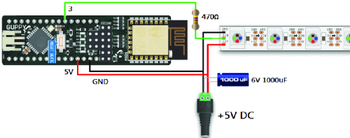
Fig. 2
PYTHON DEVELOPMENT
To develop the Wi-Fi controller, we chose Python because it is a modern, flexible, intuitive and easy to learn a language; it is also cross-platform, so the code we wrote can be run on Windows, Apple operating systems and Linux (in our case on Raspberry Pi Pi). On the official website, we can also find a complete guide to this coding language.
We open the newly installed IDLE program, which looks like a simple notepad, but allows us to write and run programs in Python: we immediately save the empty file in the same folder where neopy.py is located.
Through the NeoPy library we have the following commands available:
- Set(N, (R, G, B)): we can set the LED number N (in our example from 0 to 55) with the colour formed by R, G, B (each can assume a value from 0 to 255); for example, to set the fifth LED to green the command will be object.Set(4, (0, 255, 0));
- SetAll((R, G, B)): very similar to the previous command, but in this case, we set all the LEDs on the same colour paying attention to the double parentheses; for example to set all the LEDs to blue the command will be object.SetAll((0, 0, 255));
- SetBrightness(L): is used to set all the LEDs a percentage of brightness L (value between 0 and 100), default value 80; for example, to set half of the brightness the command will object.SetBrightness(50);
- Wheel(V) object: returns a type value (R, G, B) based on the V parameter passed (value between 0 and 255 that passes all colours); for example to set all LEDs to a random colour the command will object.SetAll(object.Wheel(RAND_NUMBER) object);
- Show() object: it is used to effectively send the UDP command via Wi-Fi and make effective all the changes we have made, physically setting the LEDs.
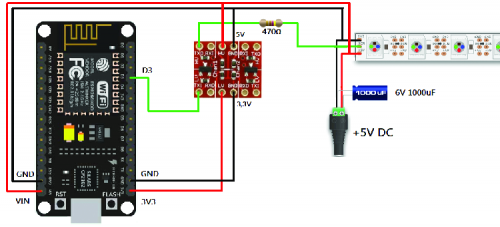
Fig. 3
Now that we know the available commands, let’s write this simple program:
from neopy import NeoPy import time
star= NeoPy(56, “192.168.1.3”) star.SetBrightness(30)
for i in range(56):
star.Set(i, (255, 0, 0)) star.Show() time.sleep(0.5)
In the first line we imported the NeoPy library, while in the second line we imported the “time” library that we will need later to time the animation; then we instantiated a NeoPy object in the variable “star” indicating 56 LEDs and the IP address 192.168.1.3 (the default port is 4242 and must be the same as in the sketch).
We then set the overall brightness to 30% and we created a for cycle in which, at each step, the variable “i” will assume values ranging from 0 to 55, always at each step we set one LED at a time on the red colour with the method “Set()”, then update the LEDs with “Show()” and wait for half a second thanks to the object “time”. Let’s be careful to align the three commands inside the for loop with a tab; otherwise, Python will give us compilation error, save and press F5 to run the program: if everything has been set correctly, we will see the NeoPixels on the star animate.
We can instantiate as many objects as we want, for example with the following program we instantiate both the star and the NeoPixel strip and then color them one in white and the other in red:
from neopy import NeoPy
star= NeoPy(56, “192.168.1.3”)
strip= NeoPy(150, “192.168.1.19”)
star.SetAll((255, 255, 255)) star.Show() strip.SetAll((255, 0, 0)) strip.Show()
In the project repository downloaded from GitHub, we can also find the files “examples_star.py” and “examples_strip.py” that contain some examples and will help us to understand the various scripts better, in order to create the animations.
Let’s move now to Raspberry Pi to try the same Python scripts we created and started on the PC: let’s download a new Raspbian image from (Raspbian Lite will be fine as we don’t need the graphical interface), write it on the MicroSD with Win32DiskImager, insert the MicroSD in Raspberry Pi, feed Raspberry Pi and connect it to the same network our NeoPixels are connected to. With an SSH terminal (such as Putty or MobaXTerm) we connect to Raspberry Pi (user “pi”, password “Raspberry Pi”) and move to the folder “pi”:
cd /home/pi/
We install git with the command (where required we press Y and ENTER):
sudo apt-get install git
Here, too, we download the files belonging to this project from GitHub and enter the relative folder with these two commands:
git clone https://github.com/open-electronics/NeoPy cd NeoPy/
Check if you are in the same folder as the file “neopy.py” with the command ls -l and create a new file “test.py”:
nano test.py
Copy the code of the small program previously written to turn on the star one LED at a time and close the file saving it with CTRL+X, then Y and ENTER.
Now, let’s try to run the program with the command:
python3 test.py
The NeoPixel star will light up just like when we launched the same program on the PC; this serves to avoid keeping a PC on to act as a Wi-Fi controller for all NeoPixel installations: rather we’ll keep on Raspberry Pi which is much more compact and less expensive than electricity.
Now let’s suppose that we have created several Python programs on our Raspberry Pi; each program performs different effects on our NeoPixel installations and must be executed at certain times of the day.
It would be very uncomfortable to remember to launch them manually every time, and for this reason, crontab comes to our aid; crontab is a scheduler present in Raspbian to which we can indicate the exact moment in which we want to launch a program: at first impact, the syntax will be a bit ‘complicated, but we will analyze it in detail.
Let’s type the command:
crontab-e
The first time we will be asked which editor we want to use to edit the schedule file we type the command: 2 (Nano)
and let’s ENTER; this will open the editing window to insert the lines of the tasks, each line corresponds to a program that we want to execute and must be composed of six parameters separated from the space: MI H D MO DW COMMAND.
Let’s see the parameters in detail:
- MI: minutes, a value from 0 to 59, or * which means “all”;
- H: hours, a value from 0 to 23, or * which means “all”;
- D: day of the month, a value from 1 to 31, or * which means “all”;
- MO: month, a value from 1 to 12, or * which means “all”;
- DW: day of the week, a value from 0 to 6 (where 0 is Sunday, and 6 is Saturday), or * which means “all”;
- COMMAND: the command to execute (remember always to enter the full path to the Python file). Let’s move to the bottom of the file and write this line:
0 * * * * python3 /home/pi/NeoPy/test.py
We have just set the execution of our test.py at minute zero, of every hour, of every day of the month, of every month, of every day of the week; we can now save and close the file with CTRL+X, then Y and ENTER and wait for the new time stroke for the script start and check that the star lights up just as if we had launched the script by hand: in this way we can schedule the execution of all the scripts we want by adding new lines in the crontab.
CONCLUSION
With the NeoPixels controlled in Wi-Fi and the scheduling system on Raspberry Pi we can, for example, place a LED strip in the room and simulate the sunrise at a specific time to create a luminous alarm clock, or we can create beautiful lighting effects in the garden after sunset.
Besides, by placing the LEDs in some rooms of the house, we can switch them on in a timed and random way to simulate our presence in the house or, again, we can connect sensors to Raspberry Pi and control the lighting according to their status.
FROM OPENSTORE
Switching-mode power supply 50W 5V
STRIP 150 LED RGB ADDRESSABLE WS2812B – NEOPIXEL
STRIP 300 LED RGB ADDRESSABLE WS2812B- NEOPIXEL
FT1300M – CHRISTMAS STAR WITH LED NEOPIXEL
