
We make a device that allows GPRS connectivity via the USB port of any PC or USB host device.
Internet connectivity via mobile phone network is now an extremely widespread reality and many of us use it in a transparent and unconscious way using common objects such as tablets and smartphones. However, this is not so obvious because in some embedded devices or even in Personal Computers used in particular situations, it can only be obtained by using the classic external modem; for example when you do not have a WiFi infrastructure or wired access to the Internet, or when you need to establish a point-to-point connection for dedicated software that, due to unavailability of support or confidentiality, do not let their data pass through the web and its servers and related services.
For this reason, we have realized the circuit that you can find in these pages, which is basically a complete GPRS modem implemented thanks to the use of a SimCom SIM800C cellular module mounted on a special base that simplifies its integration and saves, for those who are not adequately equipped, having to solder it; the card with the module already mounted can be found online on Open Electronics with the code FT1308M. The module is interfaced with a USB converter that allows its management and communication through any USB port of a computer, tablet or device that has a host USB interface, including several microcontrollers (Microchip, for example) that integrate it.
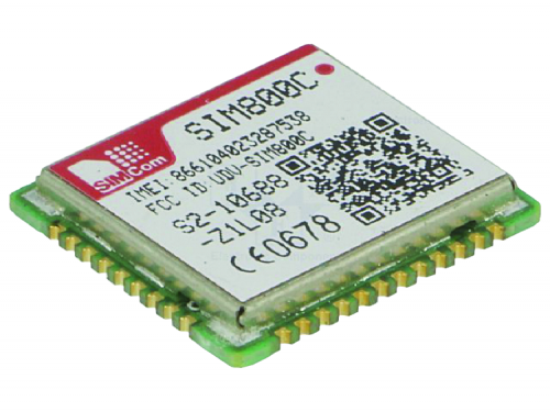
Fig.1
Like all GSM/GPRS modems, it allows both access to the Internet by means of data packeting to and from a web address, and the direct establishment of a communication between it and another modem, fixed network or mobile phone that is, for the purpose of exchanging data that cannot or must not pass through the web; it is clear that in the latter case the connection is not particularly fast, in fact, it takes place in GSM data mode and can, therefore, go up to a maximum of 19,200 bps. Direct communication, therefore, makes sense only when the limited data-rate is sufficient: for example to receive or transmit the records of a GPS tracker with GSM connectivity, send data from remote sensors etc. that transmit periodically, exchange information on confidential files and in any case where the 19,200 bps allowed is sufficient.
Moreover, no less important is the possibility to use our modem to create, together with a PC, an SMS machine, then combine it with a dedicated software that allows, through AT commands, to send a series of messages to a database of telephone numbers (not forgetting the limits imposed by the GDPR). The use for sending SMS from Personal Computer is, together with the possibility to establish point-to-point connections, what makes our modem not replaceable by a 4G key.
Circuit diagram
Let’s take a look at this small and compact modem, which is basically composed by the SimCom SIM800C module mounted on the appropriate adapter card (you can find the set signed GSM CARD in the wiring diagram on the next page), by the TTL/USB converter signed U2 and by a voltage regulator; between module and TTL/USB converter there is the classic logic level adapter, useful because U2 works at 5 volts while the serial port of the module works with 0/3.3V logic levels. The adapter card (Fig. 2) contains, in addition to the module, the socket for the SIM and the MMCX connector to connect the antenna, possibly via an MMCX/SMA adapter cable.
From the configuration, it is evident that the SimCom module is interfaced to the USB through the UART serial port with which it is equipped, which is connected to the TX and RX signals, through which it receives the control commands (the normal AT commands plus the extended ones specific for the integrated modem) and through which the data are transmitted and received.

Fig.2
SIM800C is a GSM/GPRS-edge tri-band module (900, 1,800, 1.900 MHz) GPRS multi-slot class 10 (default) or 12 compatible with the GSM phase 2/2+ (2G/2.5G) standard and therefore able to communicate with a theoretical data-rate up to 115 kbps (typically SimCom guarantees something less, i.e. 85.6 kbps symmetrical, i.e. both downlink and uplink); it can support SMS and voice communication, provided that a microphone and a loudspeaker are connected to the microphone (MIC1IN and MIC2IN (differential input) for the microphone (to be connected to the jack marked MIC in the wiring diagram) and SPK (-, L, R) for the loudspeaker (it is a bridge output, therefore raised from ground and therefore not to bring the negative to ground).
It is managed by means of standard GSM extended AT commands (set GSM07.07, 07.05) and SimCom owners (the “extended AT SIMCOM commands”) sent to UART.
The module is internally coordinated by a microprocessor that manages the telephone communication, the data communication (through an integrated TCP/IP stack) and the dialogue (through a UART and a TTL serial interface) with the circuit to which the mobile phone interfaces, i.e. with the Personal Computer.
The processor also manages a 3 or 1.8 V SIM to be mounted outside the module.
In addition to the above, the SIM800C integrates an analog interface, an A/D converter, an RTC, an SPI bus, an I²C bus, and a PWM module. The mobile radio section is GSM phase 2/2+ compatible and its transmitter as radiated power is class 4 (2 watts) at 850/ 900 MHz (GSM 850 and EGSM 900) and class 1 (1 watt) at 1800/1900 MHz (DCS 1800 and PCS 1900).
The modem part supports PBCCH, PPP stack, CSD mode up to 14.4 kbps and CS 1, 2, 3, 4 encoding schemes.
The power supply foreseen for the module is a DC voltage of 3.9 V referred to ground and the absorption at maximum transmission power reaches 1 ampere.
The TTL serial interface is used both to communicate data related to received and incoming SMS during TCP/IP sessions in GPRS (the data-rate is the one provided by GPRS class 10: max. 85.6 kbps), and to receive commands from the circuit (in our case, from the PIC that governs the remote control) that can be both standard AT and those of the SIMCom enhanced AT proprietary set.
The module is supplied with a DC voltage between 3.4 and 4.5 V and absorbs a maximum of 0.8 A in transmission; the power supply is applied to contacts 17 and 19 (Vdc) with respect to the ground, which belongs to contacts 18 and 20.
The input for the MIC microphone is filtered by capacitors referred to ground and between the two input pins in order to limit the band and retain any noise picked up by the connections; the output for the loudspeaker is also filtered by capacitors in a similar configuration, necessary, this time, to suppress spurious pulses deriving from the digital/analogue conversion of the audio signal.
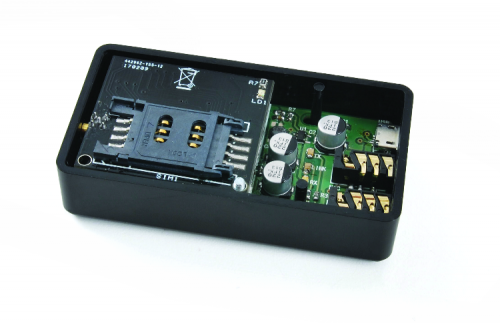
Fig.3
The ON/OFF pin of the module is used to turn it on (logical 1) or to send it to standby (low level) and in this case, not wanting any management from outside, we connect it to the R/C network formed by R5 and C11, in order to obtain the soft-start, that is to say, to keep it off when the power supply is applied and let it turn on and become operative after about 6 seconds, which is the average start-up time.
The output marked LED is used to drive the status LED called LINK in the diagram, which actually corresponds to the field LED of the mobile phone, with which the presence of the GSM network, the connection status of the module (no network signal, network presence, etc.) is signaled.
Now let’s move on to the UART, which refers to the TXD (output) and RXD (input) lines interfaced to the USB/TTL converter by means of the level translators realized with Q1 and Q2, of which we explain the operation starting from the RXD line and then from the translator belonging to the MOSFET Q1: when pin 2 of the converter U2 is at high logic level, the protection diode inside the MOSFET Q1 (placed between drain and source) is forbidden because the source is negative (it is at 3.6 volts) compared to the drain (which is maintained at 5 volts by the pull-up resistor R9) and despite the pulse does not reach the RXD of the module, the latter is maintained at logic 1 by its own pull-up resistor R8, powered with the same 3.6V of the Vcc pins. Instead, when the TX contact of the USB converter goes to logic zero (0V), the MOSFET is still forbidden (because its gate is polarized with 3.6 volts) but leads its protection diode, since the source is at 3.6V while the cathode is at zero, so the low level on the cathode itself drags the contact 14 of the GSM module to logic zero (0.6V to be exact). The RXD channel is unidirectional, so the opposite situation does not arise and therefore it is not the case to analyze it.

Fig.4
Let’s now move on to the TXD line, also unidirectional, explaining that when the contact 12 of the GSM module is at a logical one, the Q2 protection diode leads and brings this level back to the RX of U2; the MOSFET remains forbidden because source and gate are equipotential. Instead at a low logic level on the TXD, the MOSFET conducts because its source is now negative with respect to the gate, kept at +3.6V and the respective drain drags the RX line of U2 to ground, which therefore repeats the logic zero.
Let’s stay now a moment on the converter CH340 to analyze the circuit portion: it is a USB device that realizes the function of bidirectional converter from TTL to USB powered from the USB side through the 5 volts of the host connected through the USB1 connector. The component supports the USB 2.0 USB standard and has a full-duplex UART serial interface, integrated receive and transmit buffer and supports data-rate from 50 bps to 2 Mbps. It also handles UART side (although we do without it in our project) the RTS, DTR, DCD, RI, DSR and CTS control signals of the RS232 standard. The clock needed to operate the integrated unit is obtained from the internal oscillator, while the C12 is used to filter the voltage of the internal regulator.
On each of the TX and RX lines a polarized status LED is applied through a resistor, all connected to the 5V positive: each LED signals the activity of the reception and transmission data channels on the UART interface.

We conclude the circuit analysis with the U1 voltage regulator, here used to obtain the power supply of the GSM module starting from the 5 volts available on the USB; the component is an LC3406 and it is a DC/DC step-down high efficiency (96%) buck type DC/DC, capable of delivering a current of 1.2 A (necessary, since the module absorbs about the same at maximum transmission power). The integrated unit accepts DC input voltages in the range between 2.6V and 7V and provides an output voltage defined by the R6/R7 resistive divider, which reports a portion of the output voltage (taken downstream of the L1 filter inductor, driven by the SW output) to the FB feedback input; the output voltage range can vary from 0.6V and the value applied between the IN and ground pin. Due to the high switching frequency (1.5MHz) the L1 and C3-C4 filter components can have very low values and therefore very small dimensions, to the advantage of miniaturization of the circuit.
The LC3406 integrated unit includes a standby mode that can be activated by means of the EN pin, which allows leaving the component powered, deactivating it or making it operational by applying a logic level to it; to be exact, by placing EN at the input potential U1 it activates, while it goes into standby, absorbing a negligible current (lower than the microampere), when EN is at zero volts, i.e. at the potential of the GND pin or in any case at less than 0.6V.
The integrated LC3406 is encapsulated in a SOT23-5 surface mount package.
Components List
R1, R2, R3: 470 ohms (0603)
R4 –
R5: 56 kohm (0603)
R6: 560 kohm (0603)
R7: 100 kohm (0603)
R8, R9, R10, R11: 10 kohm (0603)
C1, C3, C12: 1 µF ceramic (0603)
C2, C4, C11: 220 µF 6.3 VL electrolytic (Ø 6mm)
C5, C6, C7, C8, C9, C10: 47 pF ceramic (0603)
C13, C14: –
XT1: –
Q1, Q2: BSS138W-7-F
MIC, SPK: Jack 3.5 connector from CS
USB1: Micro-USB connector
GSM: SIM800C GSM module (FT1308M)
TX: Red LED (0805)
RX: Yellow LED (0805)
LINK: LED verde (0805)
L1: Coil 2,2 µH
U1: LC3406
U2: CH340C
Miscellaneous – 2×10 way 2mm pitch connector
Conclusions
The modem described here represents a practical and portable solution to provide GSM and Internet connectivity, even if its speed can be considered limited nowadays (let’s not forget that we are in the era of LTE, where data-rates of tens of Mbps are easily obtainable), Personal Computers used in the field or where there is no wired network for Internet access or mobility, but in general for all those devices that do not integrate a cellular connection natively, such as smartphones and modern tablets.
The convenience of being able to power it through the same USB port used for data connection and the very small size (larger than a “modem stick but still small) and the lightweight, making it a useful accessory to take with you in the field or in places without a wired connection.
The modem was not designed to compete with the latest 3G and LTE keys but rather for applications where you need the occasional connection or a GSM device capable of getting in touch with a similar one (or other GSM modem) to establish a point-to-point connection through which to transmit limited amounts of data, which with the keys is not feasible because they are designed for Internet access and support for TCP/IP protocol and not direct modem-modem communication.
From openstore
GSM compact interface with M95
