
Let’s combine the Fishino UNO power with the convenience of Google Home voice assistants, so that we can forget about the remote control and manage various devices with simple phrases.
With this project, we are going to exploit the new technological ecosystems that are populating our homes: the voice assistants. In particular, we will see the entire design flow of a custom action. Unfortunately, some functions are still a bit limited: for example, to turn our TV on or off we will need an external device like Chromecast and a TV equipped with CEC technology (like Anynet+ HDMI-CEC), or if we want to change the channel or turn the volume of our TV up/down it’s impossible to do it without buying devices that are not always 100% compatible. We’ll see, then, how you can extend the control capabilities of our home by using a board like Fishino UNO and a simple infrared LED, also adding that touch of personality that will make it unique!
Block diagram
To carry out this project, we will first need to “read” our remote control. To do so, we’ll use an infrared signal receiver that we’ll connect to Fishino. Then, with the same board, we will replace the receiver with an emitter that will take care of the communication with the TV. Fig. 1 shows a schematic diagram of how infrared communication works, which will be discussed in more detail in the following paragraphs.

Fig. 1
Let’s now see what will be the data flow of our project: Google Assistant once received a trigger phrase set by us will send the message to the cloud of the IFTTT app that will process it and execute the command. The latter will send a GET request on the public IP of our modem, which in turn will redirect it to the Fishino UNO board. Finally, the signal will be sent via the connected infrared LED. It may seem very complex, but it is very easy to achieve. Also, the system processes the entire data flow very quickly without suffering from any particular latency. Fig. 2 schematically represents what has just been explained.
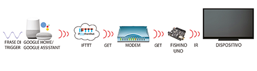
Fig. 2
Transmitter Operation
To send our infrared signal, we will use a simple LED with code 1418-LED5IR) capable of emitting light radiation in the infrared spectrum. This radiation is not visible to the human eye. Still, if, for example, we tried to press a button on our remote control and frame the LED with the camera on our mobile phone, we would notice that the component actually turns on and off very quickly. In particular, each remote control uses its protocol and frequency to send the signal, although there is a tendency to standardize products on the 38kHz frequency. The choice of this frequency is not random; it is very difficult to find devices or natural noise at that frequency, and this makes the signal less subject to noise. As far as the protocol is concerned, however, it remains different for each manufacturer. Each may differ from the others in the number of bits used to transmit the information, bandwidth, bit weight, and modulation distance between pulse trains. Fortunately, the library we will use implements the most used protocols, making our work much easier.
How the receiver works
To receive an infrared signal, we will use a simple IR photodiode receiver calibrated on 38kHz through a filter, such as TSOP58238 or TSOP38238.
Regarding Fig. 3 let’s analyze what is contained in this component.
• Amplifier and limiter: these two blocks make up what is called AGC (automatic gain control), which serves to avoid amplitude distortion of the signal, thus keeping the energy level constant. Sometimes, to reduce power supply disturbances, it is recommended to add a capacitor and a resistor near the receiver component, whose values and connections are indicated in the datasheet of the receiver.
• Bandpass filter: here, the signal is selected according to the filter pass frequency, in our case 38kHz.
• Demodulator, integrator, and comparator: these three blocks are used to intercept the information present in the signal and, in case of positive verification, to bring the output to a low level.

Fig. 3
Wiring diagram for signal reception
This configuration of Fishino UNO will only be used to store the various buttons of our remote control but will not be used to control our device. The links are immediate: just follow the directions on the component datasheet. In our case, we will use a TSOP58238, for which it will be sufficient to follow the diagram in Fig. 4.
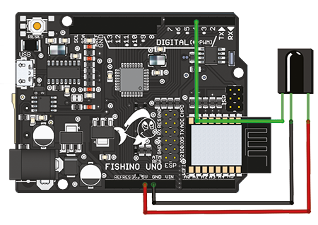
Fig. 4
Wiring diagram for sending the signal
Once “sampled” the string of each key, it will be necessary to realize the electronics that will build our IR transmitter, proposed by Fig. 5 for the use of Fishino UNO.
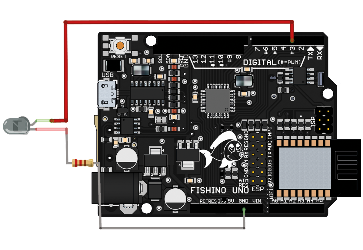
Fig. 5
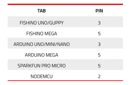
You can, however, use a different board, remembering that the pin with which to drive the infrared LED differs, as shown in Table 1.
As for the power supply, note that the most practical solution would be to power the board via a USB output of your TV. In this case, however, if you turn off the TV, the power supply is likely to fail, preventing you from using the remote control to turn it on, since in many televisions, when you turn it off, the USB is turned off while keeping the plug in the socket.
An easier alternative is to power the board with a power bank or LiPo battery. Also, if you have a Fishino UNO , the best option is to use a LiPo and add a few lines of code to the sketch to implement the LOW POWER function and extend battery life.
Table 1
Let us now focus on the infrared carrier communication mode. We premise that this paragraph is intended to show you didactically how an IR broadcast takes place, don’t be afraid, the IRremote library will do all this work for us.
Infrared communication
Take, for example, the communication protocol of a Samsung coded remote control that uses 32bit to send information. To be able to analyze the signal sent, just connect the probe of an oscilloscope to the positive pin of the infrared LED driven by Fishino UNO: by sending a hexadecimal string, for example, E0E016E9, and encoding it respecting the Samsung protocol (to do so you have to use the IRremote2.h library), you will get what shown in Fig. 6. As you can see, in the upper part, it may seem that the impulses are single, but by enlarging the image, we can see how each of them is composed of a series of very fast small impulses. In particular, we can also note that their frequency is just 38kHz! The PWM technique is then used when sending the signal.
It is important to point out that in the upper part of the image, some pulses are at a different distance from others, and this will be used by the receiver to build the information contained in the sent signal.
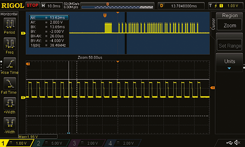
Fig. 6
The output signal from the receiver will then be amplified and demodulated. Using the Fishino UNO board connected to an IR receiver and connecting an oscilloscope probe to the pin in charge of transmitting the received signal, we send the same hexadecimal string previously generated. On the instrument, we will have a result like the one in Fig. 7. What we see is a series of lower frequency pulses representing the string. In particular, the signal is initially at a high level (unlike before) and then goes to zero for 8ms and back high for another 4ms. This indicates the start of the transmission. Then we notice the decoded sequence where the 1ms pulses indicate a “0,” and the 2ms pulses indicate a “1”. The result will be the binary code shown in the figure, which in hexadecimal is E0E016E9!
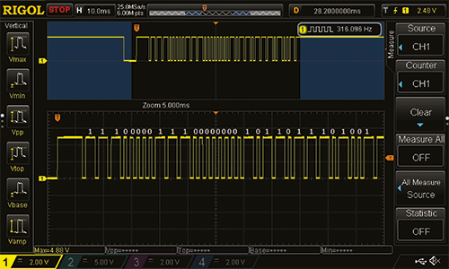
Fig. 7
Using the IRremote library in sending and receiving
The library on which the whole project is based is IRremote, and, as already mentioned, it will allow us to decode and then recode a data packet transmitted via infrared. Without this library, the work would have been much more complex. We proceed by dividing the role of the library into two parts: receiving and sending the signal.
As far as the reception is concerned, we will use the diagram in Fig. 4, and we will load on the board the ArduinoRemoteReceiver.ino sketch (Listing 1). Now let’s analyze the code; the first thing we notice is the irrecv object(RECV_PIN), which indicates the pin of the board to which the receiver LED pin is connected.
Listing 1
//ArduinoRemoteReceiver by Carlo Palumbo
#include <IRremote.h>
//Pin where the output of our led receiver is connected
const int RECV_PIN = 5;
IRrecv irrecv(RECV_PIN);
decode_results results;
void setup(){
 Serial.begin(9600);
 irrecv.enableIRIn();
 //Turns on led 13 whenever it receives a signal
 irrecv.blink13(false);
}
void dumpCode(decode_results *results){
 //Declaration of the array
 Serial.print(“unsigned int “); // Variable type
 Serial.print(“rawData[“); // Array name
 Serial.print(results->rawlen, DEC); // Array size
 Serial.print(“] = {“); // Start array declaration
 //Dump data
 for (int i = 1; i < results->rawlen; i++) {
 Serial.print(results->rawbuf[i] * USECPERTICK, DEC);
 if ( i < results->rawlen-1 ) Serial.print(“,”); // ‘,’ not needed on last one
 if (!(i & 1)) Serial.print(“ “);
 }
 //End array declaration
 Serial.print(“};”); //
 //New line
 Serial.println(“”);
 //Dump of raw code in case of UNKNOWN decoding
 if (results->decode_type != UNKNOWN) {
 //If the encoding is Panasonic, we will also need an address
 if (results->decode_type == PANASONIC) {
 Serial.print(“unsigned int addr = 0x”);
 Serial.print(results->address, HEX);
 Serial.println(“;”);
 }
 }
}
void loop(){
 //If it receives a signal, it shows it in hexadecimal and adds the type of encoding found. If necessary it also shows the RAW encoding
 if (irrecv.decode(&results)){
 Serial.print(“Codice esadecimale: 0x”);
 Serial.println(results.value, HEX);
 switch (results.decode_type){
 case NEC: Serial.println(“NEC”); break ;
 case SONY: Serial.println(“SONY”); break ;
 case RC5: Serial.println(“RC5”); break ;
 case RC6: Serial.println(“RC6”); break ;
 case DISH: Serial.println(“DISH”); dumpCode(&results); break ;
 case SHARP: Serial.println(“SHARP”); dumpCode(&results); break ;
 case JVC: Serial.println(“JVC”); dumpCode(&results); break ;
 case SANYO: Serial.println(“SANYO”); dumpCode(&results); break ;
 case MITSUBISHI: Serial.println(“MITSUBISHI”); dumpCode(&results); break ;
 case SAMSUNG: Serial.println(“SAMSUNG”); dumpCode(&results); break ;
 case LG: Serial.println(“LG”); dumpCode(&results); break ;
 case WHYNTER: Serial.println(“WHYNTER”); dumpCode(&results); break ;
 case AIWA_RC_T501: Serial.println(“AIWA_RC_T501”); dumpCode(&results); break ;
 case PANASONIC: Serial.println(“PANASONIC”); dumpCode(&results); break ;
 case DENON: Serial.println(“DENON”); dumpCode(&results); break ;
 default:
 case UNKNOWN: Serial.println(“UNKNOWN”); dumpCode(&results); break;
 }
 //Waits for a new signal to decode
 irrecv.resume();
 }
}
Immediately afterward, we have the results object, in which the captured information will be stored for later use within our sketch. We load the sketch, open the serial monitor, and press a button on the remote control. We’ll have a situation similar to the one shown in Fig. 8.

Fig. 8
Unfortunately, if the protocol is not NEC, RC5, RC6, or Sony, we will have to derive the signal through RAW code. Many libraries implement individual protocols, such as IRremote2 for Samsung, so looking a bit ‘on the net, you will surely find the library suitable for your TV.
Anyway, in the sketch, you will have already integrated the dumpCode function that will allow us to get the RAW code of our signal in case of different encodings; in this way, we will have something similar to Fig. 9. In both cases, we write down the on/off code of the device to use it in the next step.

Fig. 9
The signal sending test is even more immediate. All we need to do is connect the board to the LED via a 100-ohm resistor, as already shown in Fig. 5. As we can see from Listing 2, which represents the ArduinoRemoteSender.ino sketch, the first lines of code are occupied by the variables that will be replaced once with the value previously noted in hexadecimal or RAW and the other initialized to zero as suggested in the comment above.
Listing 2
//ArduinoRemoteSender by Carlo Palumbo
#include <IRremote.h>
//Enter hexadecimal value otherwise assign 0
unsigned int onHex = 0xE0E016E9;
//Enter RAW value otherwise assign {0}
unsigned int onRaw[68] = {4500, 4400, 600, 1650, 600, 1600, 600, 1600, 600, 550, 550, 550, 600, 500, 600, 500, 600, 500, 600, 1650,
600, 1600, 600, 1600, 600, 550, 550, 550, 600, 500, 600, 500, 600, 500, 600, 500, 600, 550, 600, 1600, 600, 500, 600, 500, 600, 550,
600, 500, 600, 500, 600, 1600, 600, 1650, 600, 500, 600, 1600, 600, 1650, 600, 1600, 600, 1600, 600, 1650, 600};
//If we want to send the RAW signal true otherwise false
bool isRaw = false;
// Create IR Send Object
IRsend irsend;
void setup()
{
 Serial.begin(9600);
}
void loop() {

 //If it reads the letter or on the serial sends the signal
 if (Serial.read() == ‘o’) {
 if (isRaw){
 // Enter signal name, array length and sending frequency
 irsend.sendRaw(onRaw, 68, 38); // Accendi device
 Serial.println(“Raw Inviato”);
 }
 else {
 //Use sendRC5, sendRC6 or Sony if your encoding is different
 //Enter signal name and bit length
 irsend.sendNEC(onHex, 32); // Power on device
 Serial.println(“Hex Inviato”);
 }
 }
 delay(200);
}
Immediately afterward, we have the isRaw variable that allows us to choose which type of encoding we want to use and then continue with the irsend object that is used to manage the signal we want to output. No pins can be selected in this case. The library for sending data uses the board’s internal timer to generate the pulses at the preset frequency. This is why it is important to respect Table 1 shown above.
Finally, the lines inside the loop function are used to send the on/off signal to the device if we write the ‘o’ character on the serial monitor. Here again, some clarifications: if we send a Raw encoded signal through the instruction irsend.sendRaw(rawbuf, rawlen, frequency), we are careful to insert the right length of our array and the frequency we want to use, commonly 68 for the first and 38 for the second.
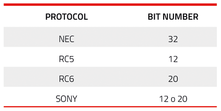
If we are lucky enough to take advantage of the library functions, remember to use the relative command (sendNEC(IRcode, numBits), sendRC5(IRcode, numBits), sendRC6(IRcode, numBits), sendSony(IRcode, numBits)) and enter the right number of bits as shown in Table 2.
Once the sketch is loaded and the ‘o’ character is sent to the board, our device (in this case, a TV) will turn on. Once you know that the system works, you can go back to the scheme used for the reception, load again the ArduinoRemoteReceiver.ino sketch and map all the buttons we are interested in encoding, noting the codes in a text file.
Table 2
The Arduino Remote sketch
Now that all the commands have been mapped let’s move on to what will be the final sketch, ArduinoRemote, which we don’t report in these pages because it’s too voluminous: you’ll find it on our site together with the other project files. The sketch has been written assuming to use the electronic configuration to send the signals seen in Fig. 5.
In the list is examined the most complex case history, that is the use of arrays of different sizes representing a raw signal. In the first lines, we can set, through the variable delayAmongSignals, the delay between the sending of a command and another to adapt it as much as possible to the reception time of our device. By default, the value is 500 milliseconds, so for example, it will take 2.5 seconds to raise the volume by 5 units. Next, we have a list of all the commands that we have previously noted down. In this case, a TV remote control has been mapped with its main controls, such as on/off, channel number, volume, and “OK” button. This last command is useful to speed up the channel change in case the TV waits a few seconds before doing so.
As already mentioned, it will be necessary to replace the present commands with the mapped ones, and, in case of non-raw encoding, it will also be necessary to modify the functions adopted for sending the signal.
Below, we have the configuration part of Fishino UNO as a web server.
Let’s go over the parameters that are required for its operation.
• #define MY_SSID “Insert SSID”.
Enter the name (SSID) of the WiFi network.
• #Define MY_PASS “Enter Password.”
Enter your WiFi network password.
• #define IPADDR 192, 168, 1, 114;
#define GATEWAY 192, 168, 1, 1;
#define NETMASK 255, 255, 255, 0
Use an available IP on your network and the right values for the gateway and netmask. If you are not sure of these values, you can use the terminal and type ipconfig on Windows or ifconfig on Mac. An example of configuration is shown in Fig. 10. As for the gateway and the netmask, we’ll just use the same values. For the IP, we’ll just change the last set of digits as we like.
• FishinoServer Server(3000)
The port on which the board will listen is defined. Let’s try to choose a large enough number and avoid door 80.

Fig. 10
We now move on to the loop function.
The first lines leave the board waiting for a client, which, once connected, forwards its request, which is inserted in a buffer and then analyzed with the processLine(buf) function. The latter ensures that it is a GET type request and then copies that request into the command variable. The following are the checks to see if the request corresponds to an action to be performed. The first is immediate. Check that the first six characters in command match the string “turnon” and then send the on/off signal to the TV. The second and third controls are used to recognize the volume increase and decrease command. Their functioning is specular, so it will be enough to analyze the first to understand the functioning of the second. The first instruction we encounter advances the pointer that represents the beginning of the 17 character buffer string. This number is very important in case we want to customize the commands to find:, taking as an example our sketch and a hypothetical request to raise the volume, we will have in buf a string of this type: GET /? volumeplus=2 HTTP/1.1. Note how the characters before number 2, which represents our increment value, are just 17. They are then copied inside a temporary variable of size 3. In this way, we can adjust the volume from a minimum of 1 to a maximum of 99 units (the last element of the array is reserved for the termination character).
The next step is to transform the string into an integer and, through a for a cycle, execute the command to send the signal to the TV as many times as the numerical value of the volumePlus variable. Finally, the last control is used to manage the change of the channel, the procedure to get the figures is identical to that of the visa for the volume adjustment, but it needs a few more little tricks.
The difference is that this time we will have to send the single digits, and to do so, we use the changeChannel(int numChannel) function. The latter receives an integer that represents the channel number we want and, using an algorithm, saves the individual digits in an array by entering a 0 if the number contains fewer digits than the maximum set (5). So, if we requested channel 208, our array would contain the following digits: 00208.
We just have to send the single digits with the sendDigits function (arrayChannel[i], numStart), avoiding the initial 0. To do this, a boolean variable numStart is used, which becomes true only after sending the first digit other than 0 and then returns to false at the end of the for the cycle. Therefore, via a switch, the individual signals representing the digits are sent and finally also the signal representing “OK” on the remote control. At the end of sending your return to the loop function and you can end the connection by listening for a later request.
Enabling a router port
To allow the IFTTT platform to communicate with Fishino UNO, we must ensure that all incoming traffic is redirected to a specific port on our router to the IP address on the board.
Unfortunately, the procedures change depending on the router model. Still, in general, you just need to enter the panel of your device by typing its IP address, usually 192.168.1.1, for routers used by TIM or Fastweb and 192.168.178.1 for FRITZ!Box routers. Once in the configuration panel, just find the “Enable,” “Port Forwarding,” or “Port Mapping” option and associate a new device. All you need to do is add the IP address or, if already listed, the name of the Fishino UNO tab. Then we will have to select the TCP protocol type and the port number we have chosen to enable in the sketch, which in our case is 3000. If the application type is required, we can select “Other” or “Create Virtual Server.” Finally, we can save it all and use www.ilmioip.it to locate our public IP. To perform a test, we can write in the address bar of the browser an address like www.insertippblicotrovato/? channel=2. By clicking on send and pointing the LED in the direction of our TV, the channel will be set to 2. If the web page does not respond, we can use www.yougetsignal.com/tools/open-ports/.it and enter our public IP address and the port we have opened, so that we can check if everything has been configured correctly (Fig. 11).
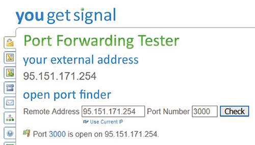
Fig. 11
The IFTTT platform
With the spread of home automation products, the need to integrate their devices within existing services has grown among makers. Thanks to platforms such as IFTTT (IF-THIS-THEN-THAT), however, it is very easy to integrate, for example, a smart lamp into the Google Assistant ecosystem by customizing the commands. It allows the creation of Applets that are triggered only when a predefined condition occurs.
The options range from automatically adding an appointment to the calendar to receiving a notification when an astronaut enters space! In our case, we will use the Google Assistant service to create a trigger that is triggered with a custom phrase and the Webhooks service to send an HTTP request with the GET method to the board we are using a web server, in this case, the Fishino UNO. So let’s start subscribing to the platform, we can do so either online through www.ifttt.com or by downloading the app from the Play Store or App Store.
Here we will use an Android smartphone, but the procedure will be very similar even if you choose to use the website. So, after downloading the app, the first thing we will be asked to do is to create an account (Fig. 12), then we choose the option we prefer, and we go immediately to create our first applet. To do this, simply go to the My Applets tab at the bottom right and click on the “+” at the top right and finally on “this.” A panel will open with a list of all the available services, write “Google Assistant“ in the search bar and click on the corresponding icon. Here we can choose the type of trigger we want to use (Fig. 13); we select “Say a simple phrase“.
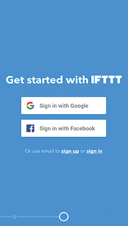
Fig. 12

Fig. 13
Before we can do this, however, we will be asked to connect our associated account to Google Assistant.
Once clicked on Connect and logged in, we set the trigger as in Fig. 14. Also, if we don’t want any response from the assistant, just enter a special character, such as quotation marks. Otherwise, we can choose a response phrase to our liking.
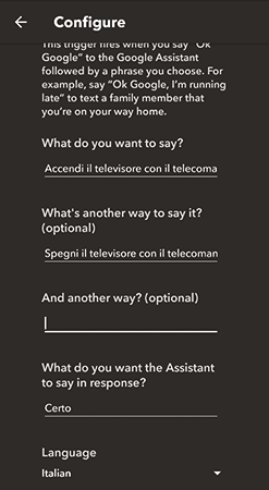
Fig. 14
It is very important to remember not to use predefined trigger phrases from Google; otherwise, the action will not be performed. Finally, select “Italian” as the language and click on “Create Trigger“. Now by pressing “that“, we search for the “Webhooks“ service (Fig. 15) and connect it to our account by simply pressing “Make a web request” and then “Connect“.

Fig. 15
Here we can set the URL to which the GET request will be sent, which corresponds to our public IP address, followed by the formatting of the request, which in this case is used to turn the TV on/off and “text/plain” as “Content-Type“. You will then have a situation similar to the one in Fig. 16. Click on “Create Action“, enable notifications if you prefer, and press “Finish“. Our first Applet is ready to be used! Finally, we create three more applets for volume control and channel switching. Unlike before, once pressed on “this” and searched for “Google Assistant“, we click on “Say a phrase with a text ingredient” which will allow us to set our phrase with what is called “ingredient” inside, which represents a variable (for example the number of a TV channel) and is represented by the $ symbol. As far as the Google Assistant service is concerned, we configure the applet for the volume increase, as shown on the left in Fig. 17 and the one for the decrease, as shown on the right in the same figure.

Fig. 16
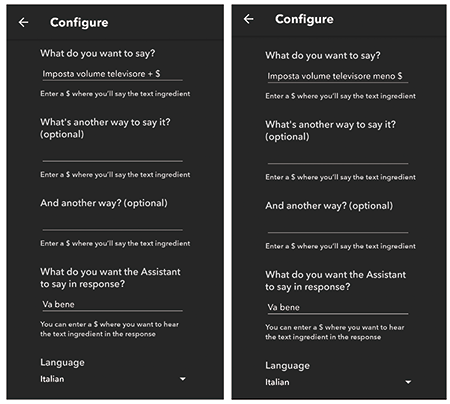
Fig. 17
Then we reuse “Webhooks“, as shown in Fig. 18, left and right, respectively. To add the ingredient: after the character “=” click on “Add ingredient” and then on “TextField” as in Fig. 19.

Fig. 18
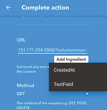
Fig. 19
To change the channel, just create the last Applet and configure it as in Fig. 20, and Fig. 21. It is important to note that the modem may change its public IP address, forcing us to reconfigure the “Webhooks” service with the new IP address even though this is rarely the case.
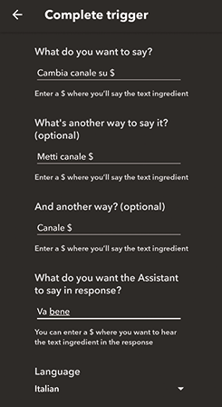
Fig. 20

Fig. 21
Conclusion
With this project, we have seen how to control a television, but there are no limits to imagination.
We can adapt it to control a DVD player, an air conditioner, any IR device, even all together with a single board.
You can also add whole actions to the code, such as entering the TV menu and setting the automatic shut down after one hour. Finally, it is useful to remember that a Fishino UNO was used for this project. Still, nothing prevents us from using any other board with an ESP8266 on board, such as the nodeMCU, obviously adapting the sketch.
We can also use a Raspberry PI with services like ngrok that adds complexity and cost to the project but allows us to have a fixed address without the risk that the public IP may change.
From openstore
