
Let’s optimize power consumption for our Arduino-like boards using specific hardware solutions and a dedicated software library.
We recently had many requests about solutions to reduce power consumption for our Fishino boards, particularly from those – among the designers – who need to activate them for short periods of time: for instance, in those applications where we have to acquire and process signals coming from seldomly-queried integrated sensors or from sensors providing periodic signals, but even when Fishino must be turned on at set times of the day. Another typical case is where we have a battery-powered system based on Fishino so it is crucial to extend autonomy as much as possible.
Actually, we had already introduced, with the second board from the Fishino series (Fishino Guppy…), the possibility to provide power using a rechargeable LiPo battery and implemented a high-efficiency, onboard power conversion through switching converters, something that is not available on the original Fishino UNO, born as a “extended clone” of Arduino UNO.
Of course, the presence of the battery is just one part of the equation, although definitely an important component.
The other thing is the possibility to reduce power consumption as much as possible and this is what this article is all about; besides analogue hardware solutions employed in various Fishino boards, we will introduce a specific library to be loaded in the sketches.
Low-power functioning
We must say from the start that low-power mode is possible, although it differs from one Fishino board to the other; so, before getting in depth, we must make a distinction between the various boards, some of which have limitations to this regard we cannot bypass.
Fishino UNO
These boards do not have switching power nor a battery input; besides, the power LED cannot be deactivated through the bridges, which causes a steady power consumption of 7÷8 mA, unless we physically remove it from the board.
Then, powering through linear regulators means that we have a non-negligible power dissipation, especially when the input voltage is much higher than the 5 V needed for the board; you can actually experience this “first-hand”, by feeling the temperature of the regulator…
Besides, Fishino UNO had some components which are always powered on, such as the USB/serial converter, the operational amplifier, the two voltage regulators and the RTC integrated circuit.
With that said, we can already mention that working consumption, with an external 10 V power source (hereinafter taken as reference for all our tasks) is about 110 mA, while the standby consumption goes down to around 15 mA, with the controller in power-down mode and the Wi-Fi module turned off.
We then have a 5/6 mA save on the energy we normally consume, and if we want to remove the power LED from the board, we can go as low as 7÷8 mA.
This means a battery life of around 133 hours with a 10 V/2000 and mAh battery in standby, or 250 hours without the power LED, so from 5 to 10 ½ days max, with the board always in standby, and something less than that if we activate it for short periods of time.
In order to set up the Fishino UNO for low-power mode, we have to make a connection, and precisely, we have to connect the CH_PD pin on the ESPCONN connector with I/O 3 (which can be replaced with another free I/O, by editing a #define in the library); we are also going to use I/O 7 to detect the Wi-Fi module rebooting after standby (Fig. 1).

Fig. 1
Fishino GUPPY
Things are getting better here, thanks to the switching power, which, with its almost 90% efficiency, provides less power leakage. The power LED is fixed on the Guppy also, therefore, unless we remove it, it will still absorb a certain amount of power, around 7 – 8 mA.
For this board, we can get a working power consumption (still with an external town volt power source) of 66 mA, or 140 mA if we power it using the 3.7 V Lipo battery, which goes down to 13 mA with 10 V or 250 mA with the Lipo, respectively, in standby. By taking out the power LED we could further reduce it to di 5÷7 mA.
Even with Guppy, some fixed power consumption is inevitable, e.g. the USB/serial converter.
Just like the Fishino UNO we need an external connection between the CH_PD been on the ESPCONN connector and I/O 3, while the I/O 7 will be used to detect the reboot of the Wi-Fi module; Fig. 2 shows the connections needed.

Fig. 2
Fishino MEGA
The situation is even better on this board, especially thanks to a breach that allows us to deactivate the power LED (we have to cut a small track closing the bridge, using a sharp box cutter, details below).
In the Mega we have a working power consumption of 75 mA with 10 V power source, or 170 mA using the 3.7 V Lipo (you can see the effect of the switching converter here!), With a USB cable connected (this causes an additional absorption of a few milliamps), and 8 mA (town volt) or 20 mA (LiPo) in standby with the power LED turned off and the USB cable disconnected. By cutting the LED bridge, those latter absorptions go down to 4 and 11 mA, respectively. This brings us to an autonomy of around 181 hours with a 3.7V/2000 mAh LiPo battery, so around 7 days and a half. Instead, using a 10 V battery on the VIN input, the autonomy goes up to 500 hours, which is almost 21 days.
As you can notice, in switching power adapters, when the voltage goes down, current goes up (the relation is not perfectly linear due to a diode in series, not present in the battery input), therefore if we power the board using a 3.7 V LiPo the autonomy goes down following the battery.
Here, we need two external connections, the first between the CH_PD of the ESPCONN connector and I/O 11, while the second one goes from I/O 7 to I/O 12.
The reason behind the second connection is that pin GPIO16 of the Wi-Fi module is internally connected to the MEGA’s I/O 7, which is however not enabled as “notify change” pin, therefore it cannot generate an interrupt when its status changes, unlike UNO and Guppy.
Both the connections to I/O 11 and 12 can be modified, provided you correspondingly add a couple of #define in the file called FishinoLowPower.h of the library and making sure you replace I/O 12 with another one capable to react to the status change.
As you can see in Fig. 3, right below the RTC chip there is a “fixed” bridge, labelled PWLED, which can be cut to turn off the green power LED, thus allowing to save the 7÷8 mA we explained above.
This bridge is set up to be cut, so you can do it without worries, just make sure you use a sharp box cutter and you don’t cut any other tracks.
In case you want to connect the LED once again, you can easily do that using a drop of tin.
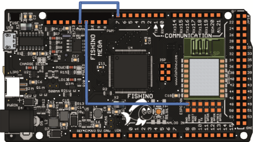
Fig. 3
Fishino32 and Fishino Piranha
These boards were already designed with power saving as the main goal, therefore they get a little “help” from the hardware in order to reduce absorption to the minimum, in fact, all the power stages can be turned off and the controller alone is left active. At this stage, which we are going to describe in the next paragraph, you can turn off all the electronics on board (except for that stage, of course), which allow us to have a really low power consumption.
Power control stage
Fig. 4 shows the power commutation stage found on 32-bit Fishino boards. A low level on the OFF input puts the Q7 MOSFET in conduction, which puts MOSFET Q6 in interdiction, but this does NOT prevents line 3V3 to flow towards the PIC power line, the 3V3Core, due to the internal diodes of the MOSFET itself, but it prevents it from powering the rest of the board and discharge a possible battery.
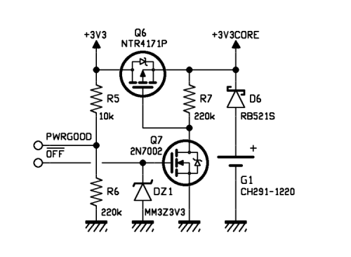
Fig. 4
It is not shown in the diagram, but you can see in the diagrams for Fishino32 board, that the OFF line is also brought back to the switching power stage, turning it off. The overall result is that there won’t be voltage on the 3V3 line, but the voltage will be present on the 3V3Core, thanks to a small, super low-consumption linear regulator connected to an external LiPo or, for the Fishino32 alone, using a small lithium G1 battery. PWRGOOD can be used to determine the presence of an external voltage source.
The “backup” regulator is a classic linear regulator (Fig. 5).
The BCK bridge (normally closed) is used to disable this function in case you want a complete switching off even when the battery connected.
On 32-bit boards we don’t have to make any external connections; all the commutations are managed by the I/Os of the PIC not linked to external connectors.
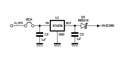
Fig. 5
Functioning and library
We have to make a distinction here between 8-bit boards (equipped with a RTC module which is however not capable to generate timed “alarms”, since it is based on the DS1307 chip) and 32-bit boards, which on the other hand have an advanced RTC inside the controller, capable of generating programmable alarm events.
For the former, 8-bit boards we will make use of the Wi-Fi module hardware, which has a precise, programmable RTC inside which can “wake up” the module itself from low consumption state through an impulse on an I/O (GPIO16).
In order to wake up the Atmega, we then have to connect this GPIO to an I/O of the controller capable of reacting to an interrupt even when it is in sleep mode.
Luckily, at least if we are talking about UNO and Guppy, this connection is already present on the PCB, since it has been used as a synchronization signal in the previous versions of the firmware. New versions do not make use of it, so we can dedicate it to this purpose!
Unfortunately, as previously mentioned in the description for Fishino MEGA, even if this connection is also present here, the I/O 7 is not linked to a controller port capable of reacting to interrupts; hence the additional connection between IO 7 and I/O 12.
The functioning is the following:
1) The library instruction FishinoLowPower.deepSleep(time) is executed in the sketch.
2) The microcontroller (ATmega) sends a command to the Wi-Fi module, telling it to enter low consumption mode for a certain amount of time (in milliseconds) or for an indefinite amount of time (time = 0).
3) The Wi-Fi module enters low consumption mode.
4) The microcontroller deactivates anything possible, it enables a pin (7 UNO and Guppy, 12 for MEGA) for waking up via an interrupt, and enters low consumption mode.
5) In case of an indefinite time, we must instruct the ATMega to react to an external interrupt on another pin of our choice through a dedicated library function, otherwise, it will not wake up ever again! This can be done using the library function FishinoLowPower.enableInterruptPin(pin), and making sure you choose a pin capable of reacting to an external interrupt (anyone for UNO and Guppy, just a few for the MEGa, as you can check in the file FishinoLowPower.h).
6) It is, however, possible to activate both timed wake and external interrupt wake; the wake up will take place upon the first of the possible events.
7) When sleep time is over, the Wi-Fi module will send in impulse on the I/O 7 which will activate the wake-up sequence of ATmega; alternatively, this can be triggered by another event.
8) ATmega will fully wake up the Wi-Fi module by resetting it; it is, of course, necessary to execute the Wi-Fi connection before continuing.
From this point on, everything will go back to normal operation after calling function deepSleep().
The example sketch provided with the library executes the module settings in the setup() and launches the loop() which immediately puts everything to sleep for a certain number of seconds, then it executes the connection to the Wi-Fi router after the wake up, downloads a webpage from the website, displays its on the serial port and goes back to low consumption mode.
As you can see in List 1, this is a pretty simple thing to implement!
List1
void setup()
{
............
#ifdef _FISHINO_MEGA_
FishinoLowPower.enableInterruptPin(A8);
#elif defined(_FISHINO_UNO_) || defined(_FISHINO_GUPPY_)
FishinoLowPower.enableInterruptPin(A0);
#elif defined(_FISHINO_PIC32_)
FishinoLowPower.enableInterruptPin(2);
FishinoLowPower.enableInterruptPinPullup(2);
FishinoLowPower.enableSerial0Wakeup();
#endif
// for FISHINO32 use full power off
// REMEMBER, you MUST have a battery connected for it...
// otherwise, just comment following line
#ifdef _FISHINO_PIC32_
FishinoLowPower.enableFullPowerOff();
#endif
.......................
}
void loop()
{
// go in sleep mode for 15 seconds
// (or less if external interrupt wakes us up)
FishinoLowPower.deepSleep(15000);
DEBUG_INFO(“Connecting to access point\n”);
wifiConnect();
DEBUG_INFO(“Sending request\n”);
httpRequest();
DEBUG_INFO(“Waiting for data\n”);
uint32_t tim = millis() + 500;
while(!client.available() && millis() < tim)
;
DEBUG_INFO(“Reading and printing data\n”);
while (client.available())
{
char c = client.read();
DEBUG_INFO_N(“%c”, c);
}
DEBUG_INFO_N(“\n”);
DEBUG_INFO(“Stopping client\n”);
client.stop();
}
In the setup() we can notice some #ifdef used to tell the code apart from the various boards; if you have only one of these, you can, of course, remove the section of code referencing the others.
For 32-bit boards, things are quite different, as previously mentioned, here, we take advantage of the controller’s internal RTC and not the one found in the Wi-Fi module. But why? Well, simply to be able to turn everything off, including the Wi-Fi module, and when we say “turning off” we literally mean “cut the power”.
In 32-bit boards, in fact, low consumption was already in the main goal during the design stage, especially thanks to high I/O availability of the controller, which allowed us to dedicate a lot of I/Os to this purpose; in particular, a digital output is connected to a section of the circuit capable of cutting off the power for everything “superfluous”, leaving only the PIC powered on and nothing else.
Of course, this is just the first step and we need to put the PIC itself in low consumption mode, which is done by our code, as explained below.
1) In the sketch, we execute the FishinoLowPower.deepSleep(time) instruction; here, the “time” field can be null, corresponding to unlimited time. Unlike the RTC in the Wi-Fi module, the one included in the PIC mainly aims to work as a clock, therefore time resolution is rather low, i.e. 1 second, and not a microsecond (millisecond from the firmware’s perspective) as for 8-bit boards. This means that the set time will be rounded to nearer integer values in seconds, except for values under 500 ms (zero excluded) which will be considered as 1 second. Therefore, by setting, for instance, one millisecond as time, everything will stop for one whole second; same goes if we set 1.499 ms (rounded down to 1.000 ms=1 seconds), while if we set 1.500 ms in time will be rounded up to 2 seconds, and so on. It might seem as a limitation, but in our opinion, sleep mode for shorter periods of time doesn’t make much sense, in fact, the circuitry must carry out a lot of operations to reactivate everything.
2) The library saves the status of the RTC module (including possible set alarms), of the peripherals (whether activator or not, powered or not), external interrupts and I/O ports.
3) The system then turns all unnecessary peripherals off (unless explicitly required by functions FishinoLowPower.enableXXXXWakeup(), where XXXX can be any one of the peripherals capable of waking up the PIC through an external event). Attention: any peripheral left active will absorb power, therefore we will not save as much!
4) Next, all the unnecessary and/or not required I/O ports would be turned off through the function FishinoLowPower.portUsed(); this might be necessary if an I/O must stay at a defined level because, for instance, it controls a peripheral that might get “confused” if the port is disconnected. The activation is done by putting the I/O’s and analogue mode, which is the least power-absorbing one.
5) Here, it is also possible, through function FishinoLowPower.enableInterruptPin(pin) to enable wake up through external events; moreover, we have two functions, FishinoLowPower.enableInterruptPinPullup() and FishinoLowPower.enableInterruptPinPulldown() allowing to insert an internal pull-up (or pulldown) resistor in order to avoid inserting additional external components. For instance, by enabling a pull-up and in certain a button to the ground we can wake up the device by pushing the button. In this case, also, the more ports stay “open” the higher power consumption will be, even if just slightly; power absorption goes sensibly higher if ports are then connected to low-value resistors or, even worse, to LEDs that stay on.
6) Next, if we have required it using the function FishinoLowPower.enableFullPowerOff(), the controller will physically turn off all the external components, including status and power LEDs reducing power absorption to a bare minimum.
7) Finally, the microcontroller will also enter sleep mode, stopping its operation.
8) When an external event is received (or once set a time is up) everything will revert back to normal, the CPU will exit sleep mode, and will immediately reconnect power, restore the status of peripherals and I/O’s, reactivate (and reset) the Wi-Fi module etc., returning to a fully operational state.
As you can easily understand, when you go “backstage”, everything that seems mundane actually is not!
By taking all these measures, we managed to reduce absorbed power, measured on the 3 V battery found on the Fishino32, to 270÷350 µA (microampere) of absorption, allowing the system to operate for many days with the LiPo battery connected.
A note in this respect: on the Fishino32 we can find, as previously mentioned, a case for 3 V, not rechargeable, maintenance battery. This feature is not currently implemented in the software, so do not insert it, if you don’t want to drain the battery in a few seconds!
The battery case has been included as a preventive measure in order to manage, for instance, the replacement of the LiPo battery without losing time and settings of the board’s saved on the RTC; unlike 8-bit boards, equipped with a dedicated external RTC, the battery directly powers the main controller which, even if in super low consumption mode, absorbs, as mentioned above, around 300 µA, which is not much, but it is definitely too much for the limited capacity of the battery which is just 35 mAh! A quick calculation tells us that the battery can in fact keep the controller active (in standby) for a few days (3÷4 tops) and not four months as it is the case for 8-bit boards where the RTC absorbs just a few tens of nanoamperes.
However, in order to take advantage of this feature, although limited, you will have to wait for the new version of the bootloader which will include a mechanism for force-turning off everything in case of no external power, in order not to drain all the battery charge in an instant. Therefore… If you really want to try it out, you currently have to “manually” provide, via software, a mechanism to read the power voltage and turn everything off in case that goes to zero, in the shortest time possible.
However, we do not recommend to do that, unless you definitely need to; using the external LiPo battery, the economy is already huge; in fact, we’re talking about over 6500 hours of standby operation using a 3.7 V, 2.000 mAh battery, corresponding to over 270 days!
Finally, Table 1 shows consumptions measured in various working conditions, for all our Fishino boards.
Table1
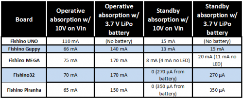
As you may notice from the table, the switching power source you can find from Guppy onwards already allows cutting power absorption in half, with 10 V external power, unlike the UNO which is not equipped with that. Another great save in power is provided by the stage turning out the power on the 32-bit boards, reducing standby absorption to almost zero.
The FishinoLowPower is included in the packages of libraries you can download from www.fishino.it.
Conclusions
This concludes the presentation of the FishinoLowPower library, we hope you will find it useful for your portable applications projects or, in any case, for any battery-powered applications or energy harvesting solutions, even if not portable.
The library used, along with the hardware solutions suggested in the previous pages, allows to get good results, the hardware modifications, on that hand, provide useful upgrades, even for the first boards of the Fishino series, which are not equipped with power consumption reduction sections, as is the case on Piranha and Fishino 32.
From openstore
