
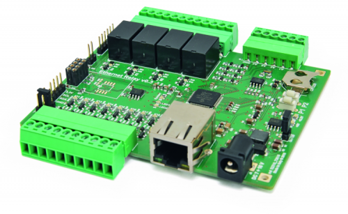
LAN interface with 4 relays, 8 programmable I/Os and 4 analog inputs, IoT-ready.
How many times have you read or heard about the Internet of things (Iot)? The Internet of things is an expression that is becoming more and more popular lately; it represents the expansion of the Internet into the world of objects and physical locations. Thanks to this technology, many objects that used to be exclusively passive, can now become interactive and coordinate between themselves and interact with the user; they become more intelligent and thanks to the Internet connection they allow to share generated data with the user or another board that can also be in another continent. However, in this scenario, the term “intelligence” is often misused. In fact, many times the IoT includes not only electronic devices capable of making autonomous decisions in order to simplify our everyday life, but also the plethora of products that used to be stand-alone. For this reason, all we have to do is equipping our older devices with an Internet connection.
OUR SYSTEM
The project we are introducing in this article wants on to take on that task by creating, through dedicated connections, the possibility to remotely control your entrance gate, your fish tank, the garden lights, the watering system and so on, using numerous examples. It is an ethernet-controlled relay board, which can be used as an actuator to directly control 220 V loads, to command 0V ÷ 5V digital signals or to read the status of digital or analog inputs; everything can be done remotely by using an Internet capable LAN.
Nowadays, there are many alternatives to take advantage of remote controls, however, the board we are proposing here is simple both in terms of electric connections and in terms of user interface. The board has a powerful integrated Web server that allows, using a browser, to access the control panel. Besides, it allows setting a username and password in order to login protect the access. This way, changing the output status (relays or additional signals) and controlling the inputs status (digital and analog inputs) becomes a really simple and immediate operation. Finally, implementing a Web server allows creating alternative control interfaces (for instance, smartphone apps) since all the functions of the control panel are available through dedicated web APIs.
CIRCUIT DIAGRAM
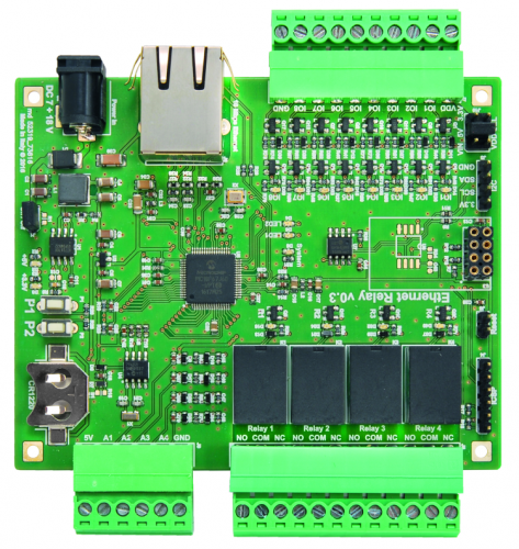
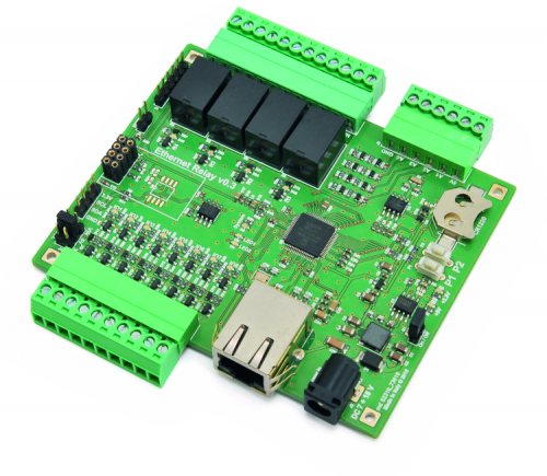
In this section, we are going to see the circuit diagram of the proposed board, then we will understand its limitations and potential from an electric and electronic perspective. The heart of the board is represented by the PIC18F67J60 (U5) microcontroller which is tasked with controlling the release status through MOSFETs Q5, Q10, Q15 and Q20, controlling digital inputs or outputs, making a digital and analog sampling of signals coming from dedicated analog inputs and finally connecting to the Internet through a 10 Mbps Ethernet port.
This 8-bit microcontroller by Microchip has a 41,666 MHz clock thanks to the 25 MHz quartz (X2) and the internal PLL. Besides, the X2 quartz with hardware multiplier allows generating the right clock for the Ethernet PHY.
Moving on, we can find the digital inputs and outputs; “direction” of these I/Os can be configured by software. For each of the 8 digital signals, the microcontroller uses to I/O lines, which, based on the configuration chosen by software, allows to dynamically change a direction of the port switching from output to inputs and vice versa.
This feature is especially useful because, according to the moment’s needs, you can reassign an I/O without stopping the system.
This is possible thanks to the particular circuits of the eight I/O’s, that we can analyze taking O1 as a reference, which is composed by two MOSFETs (Q1 and Q3 respectively for I/O 1), two pull-up resistors (R39 and R40) a LED indicator (D14 with R36 and has limited resistor) and a diode (D11) to short-circuit the overvoltage peaks generated by the relay switch estate.
The functioning logics provides that the digital output is normally at a level high through the pull-up resistor (R39) which voltage reference is chosen manually by the user through VDD SEL jumper choosing from three possible values (3,3V, 5V o VIN). The digital port can go low in two possible ways: by piloting Q1 when the microcontroller is in charge of the outputs control, or through the external signal connected to DIGITAL terminal block. This status change is amplified by Q3 on the control LED and properly read by the microcontroller as a corresponding input value. This configuration allows to control the direction of the web ports and to prevent damages in case of erroneous configuration.
As for the analog inputs, we have four ports connected to an analog-digital converter that can discriminate analog values with an accuracy of 10 bits. The voltage values allowed by the board are in the range 0V÷5V. Since the microcontroller allows to sample electric signals with a maximum value of 3,3V, we have employed a resistor grid (R43 and R46 four input 1) that acts as voltage partition or reducing 5V to a value that can be tolerated by U5.
D9 and D10 diodes normally operate in inverse polarization and contribute to protecting the microcontroller in case of overvoltage is, finally C45 and C49 stabilize the input signal allowing to obtain a more accurate sampling. As for the power voltage, it can be provided through the PWR connector and can range between 7 and 15V. the U1 component, which is an 800 kHz Step-Down switching converter, will provide the 5 V necessary to power the main parts of the board, including the relays. Then, the microcontroller and the other 3,3V components will be powered by U2, which is a Low Dropout Linear Regulator capable of providing up to 300 mA in a very small package.
Another crucial component for the board’s functioning is the U7 memory: it is an EEPROM with 1024 kbit, i.e. 128 kbytes, I²C communication interface. This serial memory allows saving web pages and user settings.
Finally, we have U4, which is a Real-Time Clock/Calendar that allows, through the backup battery B1, to save settings for time and data assigned to the board, even when there is no main power available.
During the project, we designed the board to be expendable, to this purpose, we have added the I²C connector, which provides an external access to the microcontroller’s I²C port, as well as the connector for the optional U3 module, to which you can apply an ESP8266-based Wi-Fi (e.g. ESP03) which (after an update of the U5 microcontroller’s firmware) allows making the board wireless.
HOW IT WORKS
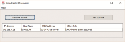
Now, after an overview of the board’s characteristics, we can briefly introduce the functioning principle and how the board is used. As anticipated, the board has an integrated Web server that allows to access configurations using a browser. The web pages have a very basic look and therefore can be accessed both from a computer or from a smartphone or tablet, so even from devices with compact displays. Now, all we have to do is get to the details of explaining how to use the board. First operation is to connect the board to a LAN network using a RJ-45 cable. The board has its DHCP client enabled. The DHCP, for those who don’t know, is that network service that allows to automatically assign the network parameters to devices connected to the LAN therefore facilitating the configuration operations. The drawback of DHCP for devices with no display is the difficulty in retrieving the IP address assigned. Given that in order to access the board, you have to know the IP address assigned by the DHCP server (which is typically in execution on the home router) you have to obtain that information. In order to know the IP we can use two options. The first is to navigate through the router’s pages searching for the list of the IP assigned in a network. However, this operation changes from one router to the other and often times from one device to another within the same brand. So, unless you have a certain familiarity with the network settings of your router, the operation might be complicated. A alternative is to use the Broadcaster Discoverer application shown in figure which we provide for Windows operating systems. The application is coded in Java and therefore easily executable without installation if you have a Java Virtual Machine, otherwise, you will first have to install this component (it can be freely downloaded). The application is a simple executable which sends out a welcome message in broadcast on the local network, the port is the 30303. Each device implementing this feature will respond with some information, among which there is their IP address. Now, after the questioning, Broadcaster Discoverer will display as many lines as there are connected boards to the local network.
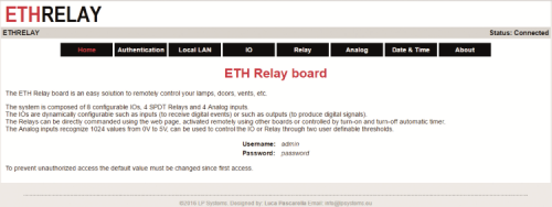
By clicking on one line on the table, the starting page of the board will open up and will be similar to figure. The homepage is a welcome page containing a series of interactive buttons and a recap of the features offered by the board. This page, since it doesn’t contain accessible information, can be accessed by anyone and therefore there is no need for authentication. Subsequent web pages allowed to modify the bay boards behavior and are protected with username and password.
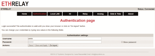
Moving on, the first page we find is Authentication, shown in the figure. This page allows to display username and password, besides, it allows to modify these parameters and log out. Since every board have the same preset username – password combo (username and password are: ‘admin’ and ‘password’ respectively), it is suggested to modify these parameters upon the first access.
Next page is Local LAN Configurations, shown in the figure. On this page, you can edit network settings, configure email notifications and set the Dynamic DNS server. First of all, under the Internet section, you can make some preliminary tests in order to measure the time necessary to ping or test the functioning of the DNS servers signed by the DHCP service by inserting a URL in the DNS test field. Under the local network section, you can edit network configurations such as MAC address and hostname (under Windows, you can use this training to identify the board instead of using the IP address). Besides, you can enable or disable the ICMP server to respond to ping requests or enable or disable the DHCP server for automatic configuration of the network parameters.

Moving on, under the Email Notifications section you can configure the SMTP service for email notifications. In this case, you can choose a service such as “email.it” which allows to freely obtain an email address with the SMTP protocol used by the board. In our example, the SMTP server will be smtp.email.it, Porta25, username, and password are chosen by you and the recipient and the subject of the email are once again chosen by you. This option allows sending an email when there is a change in the input status. In order to avoid spamming your inbox and risking to be banned from the service, the software will send a new email only if a minimum time interval has elapsed between one notification and the next one. In order to test email functioning, you can press one of the two buttons on the board for more than 5 seconds.
Let’s move on to the last fields group, related to the Dynamic DNS section. This allows taking advantage of those services to associate dynamic public address to a URL of your choice. Typical example our IP addresses assigned to commonplace home ADSL’s that changes every time your home router is rebooted. By using this solution, the board and the DNS service will be tasked with keeping the URL updated in order to always point towards the IP addresses assigned but your ADSL line.
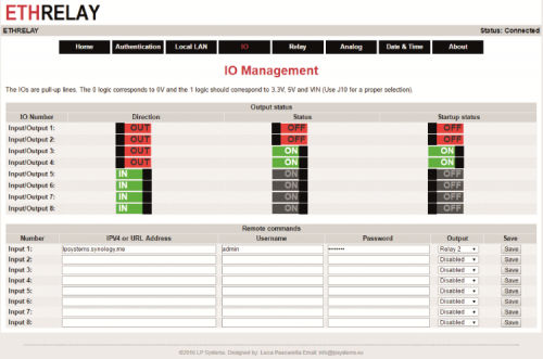
The next page is about I/O Management. On this configuration page, you can set ports direction, input or output, current status in case you choose to use the IOS output and the initial status of the output at power up. The Output status section groups this features in a simple interface that allows to set the I/O direction to input or output, display or edit current status, ON for logic level high and OFF for logic level low and to set the status of the configured I/O as output when the device is started.
Besides, since the boards respond to GET requests of the HTTP protocol, you can configure the control of a remote board corresponding to the status change of an output. In this case, under the section Remote commands, for each input line you can associate an action to make when there is a change in the input status of the associated input: for instance, input 1 will control relay 2 of a remote board that these are reachable through the URL assigned.
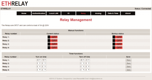
Next page allows to control the relays; figure provides a preview of possible configurations. As for the digital outputs, from this webpage, you can control the current status of the relays and their desired status when the device is powered on. Besides, under the section Timer functions, you can associate everyday events to each relay. By selecting activation time and deactivation time, the corresponding relay will activate or deactivate automatically.
Page Analog Management is shown in figure allows displaying the status of analog inputs in three different formats. The first representation visually displays the value of all sampled by coloring a horizontal bar; the second view reports exactly the sampled values at 10 bits ranging from 0 to 1.023. Finally, the third view reports the corresponding voltage value measured between 0V and 3,3V. Besides, the board allows defining two thresholds to control digital outputs or relays.

Under the section Advanced functions, you can associate events when selecting thresholds are overcame; for instance, you can set a threshold corresponding to a minimum value and a threshold responding to a maximum value in order to create a hysteresis and prevent continued status changes when thresholds are overcome. This feature is also useful in case there is a transducer associated to the analog inputs that allow measuring analog quantities such as external pressure, temperature, humidity etc. Set thresholds allow controlling both the I/Os configured as an output and the relays on the board. This way, you can, for instance, connect a photoresistor to one of the analog inputs and use the board as a lowlight actuator.
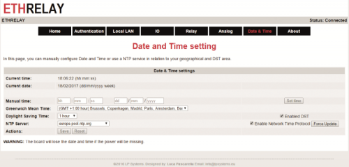
The last page we propose is labeled Date & Time and it is shown in figure This page allows to display the current time in the RTCC circuit of the board and edit it. The modification can be manual, by setting all the data fields or by enabling the Network Time Protocol (NTP). This is a service that allows getting the right time using a dedicated Internet server. Besides, from this page, you can select to choose Daylight savings time and set your time zone.
One last note regarding the procedure to reset settings.
In case you have to reset username and passwords, or if you want to reset all the choices in relation to the network parameters (e.g. if you can’t any longer reach the board using your IP address due to a wrong configuration) you can make use of the reset procedure. In order to do that, you have to press and hold for more than four seconds at startup, both keys on the board. The rest will be indicated by the D8 LED system which will quickly flash during the 4 seconds necessary to confirm the operation and will stay on waiting for the user to release the keys. When keys are released, the software will overwrite user-provided parameters with preset parameters.
When the operation is over, D8 LED will go back flashing at one-second intervals to indicate normal functioning.
GET REQUESTS
The Hypertext Transfer Protocol (HTTP) allows enabling communication between a client and a server. Typically, the client is represented by the web browser of your computer and the server is hosted by a remote service, e.g. Google. In our specific case, the server is in execution on the board and it can be reached directly from your LAN network. Accessing wet pages of a Web server can be done using two basic methods identified with labels GET and POST. Typically a GET represents a resource request from the client to the server, while a POST is a way to send a data form to the server. In both cases, the client specifies what is the resource to interact with by inserting it right after the server’s address. For instance, string http://192.168.3.10/index.htm inputted in your browser will produce a GET request, requiring the server identified by the IP address 192.168.3.10 to respond by returning the resource (file) index.htm. Basically, a GET allows to also specify a series of optional parameters by separating the resource from the parameters using a ‘?’ Just like in the following example:
http://192.168.3.10/index.htm?name1=value1&name2=value2
Parameters are specified in key = value couples = and are separated by a &. Generally, a maximum number of parameters is not present, but it depends on the service configuration. Typically, a byte limit is used in order to cut excessively long requests and prevent buffer overflow problems. These key-value couples can also be used by the server as inputs to provide a dynamic response. You could get the same result by using a POST request; the difference is that a GET typically much lighter in terms of bytes needed in these characteristics make it interesting in our case where memory resource of the server are limited. By using this technique, we can also control the status of digital outputs and relays, simply by saving the address in the list of your browser’s favorites.
To be precise, we must add that the board implements an authentication mechanism called Basic Access Authentication (BA); this mechanism is a really simple solution to authenticate the client with some information (username and password). The following example shows how the BA works: http://username:password@www.example.com/index.htm
Actually, the username: password couple is not transmitted unencrypted, but it is masked by a base 64 coding and then passed on to the server which will carry out the inverse operation in order to verify the identity of the applicant.
Using this technique, the board provides a simple access interface that can be implemented in various applications by the user through the development of smartphone apps or dedicated computer programs. In order to switch the state of an I/O, you can therefore call the following GET request
http://username:password@192.168.3.10/prt/io.cgi?io=2&act=1
where io=2 specifies I/O number 2 and act=1 brings it to logic level high.
Similarly, in order to modify the status of a relay, the command will be:
http://username:password@192.168.3.10/prt/relay.cgi?relay=3&act=0
where parameters relay=3 and act=0 tell the server to release relay 3.
Information related to inputs are on the other hand coded in an XML file by implementing a simple key/value logic. In order to find out and access the XML file, we must ask for that resource from the server just like in the following example:
http://username:password@192.168.3.10/prt/io.xml
Upon request, the server will respond with a file formatted as below:
<r>
<io1>1</io1>
<io2>1</io2>
<io3>1</io3>
<io4>1</io4>
<io5>1</io5>
<io6>1</io6>
<io7>1</io7>
<io8>1</io8>
<in1>1</in1>
<in2>1</in2>
<in3>1</in3>
<in4>1</in4>
<in5>1</in5>
<in6>1</in6>
<in7>1</in7>
<in8>1</in8>
<is1>0</is1>
<is2>0</is2>
<is3>0</is3>
<is4>0</is4>
<is5>0</is5>
<is6>0</is6>
<is7>0</is7>
<is8>0</is8>
</r>
Where string ioX represents direction all the X-numbered I/O, string inX represents the current state of the I/O and finally string isX represents the status to activate when powering on the board. Similarly, files relay.xml and analog.xml will contain the current status of relays and analog inputs.
PRACTICAL MAKING
Now, let’s move to the hints and tips to follow in order to correctly put the board together. It goes without saying that the first step is to get all the components and all the necessary to assemble the printed board. Once you have the printed board, the integrated components, resistors, capacitors, relays, connectors and everything else (LEDs, buttons, quartz, etc.) you can get to the actual soldering part. It is recommended to always practice a little bit beforehand using the more simple components (resistors and SMD capacitors), in order to get the hang of it and then move on to properly work on multi-pin components. We suggest you mount the traditionally-mounted components and the bigger components such as the relays last in order to have free access to the PCB.
In order to properly solder the ICs and all the SMD components, we suggest you spread flux gel on the components’ outline; this substance has the dual action of activating the soldering process and helping in the creation of the soldering point and to remove tin oxidation.
Oxidation is a natural phenomenon taking place for many substances exposed to air, just think about how spreading lemon juice on a slice of apple will make it go brown later, in the same way, flux gel delays the early agent of 10 and helps with the soldering.
Another suggestion, when you solder SMD components, do not go too high with the temperature of your soldering iron, because usually, there is the bad habit to set a temperature over 400°C. Although a higher temperature could apparently make the process easier, it actually gets the opposite result, that is an early aging of the tin (by burning the flux gel and fostering a quicker oxidation). By setting a relatively low temperature, ranging between 360°C and 380°C, the flux doesn’t burn out but slowly evaporates and its benefits last longer, making your work easier.
The remainder of the circuit is not critical, therefore, after correctly soldering all the superficially mounted components, we suggest to go on with the remaining through hole components, i.e. the traditionally mounted components such as relays.
Finally, we suggest using a good cleaning product for cleaning residues from the soldering process and the flux gel, using a small brush with hard bristles along your chemical agents.
SOFTWARE
In this paragraph, we are going to describe the software and the development environment used to create the firmware for our project. For what concerns the development environment, we have updated our IDE to the latest version available, that is v3.55 from MPLAB-X, we remind you that the software can be freely downloaded directly from this page: www.microchip.com/mplabx, once we get the self-installing file all we have to do is launch the installation, import our project and browse and edit the code we have just created. In order to compile the project, we have to have the MPLAB-C18 v3.47 installed. Using the C18 compiler instead of new XC8 is necessary in order to use the legacy libraries provided by Microchip containing the TCP/IP stack necessary for the good functioning of the Ethernet network. Libraries employed and the compiler can be http://www.microchip.com downloaded . The compiler, without optimization options for the code, is provided free of charge. Since the free version is sufficient to compile our project, the commercial version is not necessary.
Now, we can provide an overview of the base routine of the software.
The first function to analyze is the main which is also shown in List 1. This function is needed for two purposes: initialization of the main functionalities (including initialization of hardware peripherals) and periodical polling of each one of the handlers associated with different functionalities. The technique to periodically call the handler of every single function allows creating a multitasking program using very few resources. The difficulty of this technique is in dividing functionalities into several tasks of smaller dimensions (in terms of execution time). If each task requires a few milliseconds and the partitioning is correct, therefore without too long or too short of a fraction, the microcontroller will be able to execute more “programs” at the same time. On the other hand, by incorrectly dividing tasks we can have some problems, especially for those functions which need to be called regularly, such as the StackTask() which handles all the low-level protocol for accessing the Internet.
Listing1
void main(void) {
static DWORD t = 0;
static DWORD dwLastIP = 0;
// 1 - Initialize application specific hardware
InitializeBoard();
// 2 - TickInit must be the one of the first initialization to use the software timeouts
TickInit();
// 3 - Initialize I2C used by ExtRTCC
InitI2C();
// 4 - Initialize External RTCC (MAC Address)
InitExtRTCC();
// 5 - Initialize MPFS file system linked to internal Flash
MPFSInit();
// 6 - Check user restore trigger
checkManualRestoreDefault();
// 7 - Initialize Stack and application related NV variables
InitAppConfig();
// 8 - Initialize core stack layers (MAC, ARP, TCP, UDP) and application modules (HTTP, SNMP, etc.)
StackInit();
// 9 - NTP Client initialization
NTPInit();
// 10 - Ping handler
InitPing();
// 11 - Reboot manager
rebootInit();
// 12 - Do a DDNS connection
ddnsInit();
// 13 - Initialize HTTP Client
HTTPClientInit();
// 14 - Initialize EMail
EmailInit();
// 15 - Initialize relay
InitRelaies();
// 16 - Initialize IO
InitIO();
// 17 - Initialize Input
InitInput();
// 18 - Initialize ADC
InitADC();
// Now that all items are initialized, begin the co-operative
// multitasking loop. This infinite loop will continuously
// execute all stack-related tasks, as well as your own
// application’s functions. Custom functions should be added
// at the end of this loop.
// Note that this is a “co-operative multi-tasking” mechanism
// where every task performs its tasks (whether all in one shot
// or part of it) and returns so that other tasks can do their
// job.
// If a task needs very long time to do its job, it must be broken
// down into smaller pieces so that other tasks can have CPU time.
while (1) {
// Blink LED0 (right most one) every second.
if (TickGet() - t >= TICK_SECOND / 2ul) {
t = TickGet();
LED_0_INV();
}
// This task performs normal stack task including checking
// for incoming packet, type of packet and calling
// appropriate stack entity to process it.
StackTask();
// This tasks invokes each of the core stack application tasks
StackApplications();
// Ping request task handler
PingTask();
// NTP Handler
UDPClientNTPHandler();
InputTask();
IOTask();
ADCTask();
RelayTesk();
ExtRTCCSetTimeFromNTPTask();
rebootTask();
HTTPClientTask();
sendEmailTask();
// If the local IP address has changed (ex: due to DHCP lease change)
// write the new IP address to Announce service
if (dwLastIP != appConfig.ip.fields.MyIPAddr.Val) {
dwLastIP = appConfig.ip.fields.MyIPAddr.Val;
#if defined(STACK_USE_ANNOUNCE)
AnnounceIP();
#endif
}
}
}
Another good example of the function and principle implemented is about the handler for getting requests for the I/O. The example shown in List 2 can be easily be generalized to other cases, such as for controlling analog inputs and relays, therefore all we are going to do is describe the I/O case. The function HTTPAppGetIO(HTTP_CONN * curHTTP) is called when the web browser makes a GET request from the server by requiring the page “prt/io.htm”. Inside it, parameterized functions such as HTTPGetROMArg(curHTTP->data, (ROM BYTE *) “io”) allows to return the pointer to the key = value couple shown in the example of the string “io”. This way, the next code section can interpret the user’s request and possibly called the code which controls the inputs’ status.
Listing2
void HTTPAppGetIO(HTTP_CONN * curHTTP) {
BYTE *io, *action, *direction, *startup;
io = HTTPGetROMArg(curHTTP->data, (ROM BYTE *) “io”);
action = HTTPGetROMArg(curHTTP->data, (ROM BYTE *) “act”);
direction = HTTPGetROMArg(curHTTP->data, (ROM BYTE *) “dir”);
startup = HTTPGetROMArg(curHTTP->data, (ROM BYTE *) “st”);
if (io && action) {
setOutputStateIO(*io - ‘0’, *action - ‘0’);
}
if (io && direction) {
setDirectionIO(*io - ‘0’, *direction - ‘0’);
}
if (io && startup) {
setStartupIO(*io - ‘0’, *startup - ‘0’);
}
}
CONCLUSIONS
In this article, we have introduced the hardware and software features of this project that allows expanding your everyday user experience into the world of IoT. Besides, we have described the circuit diagram, the functioning principle and provided some hints to put your board together.
From openstore
Ethernet card 4 relays, 8 digital I/ Os and 4 analog inputs

[…] Ethernet Relay board – [Link] […]
nice project, but where can we download the files?
I don’t see any download link for the project files?
[…] Read more: Ethernet Relay board […]
[…] Tarjeta de relé Ethernet – [Link] […]
Hi Goodday
I have a project in mind that requires an Ethernet to Relay conversion PCB. I have checked this web site and feel that this product will fulfill my requirement. Will it be possible to purchase this module and the cost please. I am from South Africa.
Thank You