- Building a 3D Digital Clock with ArduinoPosted 4 months ago
- Creating a controller for Minecraft with realistic body movements using ArduinoPosted 5 months ago
- Snowflake with ArduinoPosted 5 months ago
- Holographic Christmas TreePosted 5 months ago
- Segstick: Build Your Own Self-Balancing Vehicle in Just 2 Days with ArduinoPosted 6 months ago
- ZSWatch: An Open-Source Smartwatch Project Based on the Zephyr Operating SystemPosted 7 months ago
- What is IoT and which devices to usePosted 7 months ago
- Maker Faire Rome Unveils Thrilling “Padel Smash Future” Pavilion for Sports EnthusiastsPosted 7 months ago
- Make your curtains smartPosted 8 months ago
- Configuring an ESP8266 for Battery PowerPosted 8 months ago
Embedded MP3 Player & Recorder: The firmware
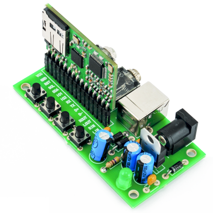
In the previous posts we presented the project of an an embedded MP3, capable of playing and recording audio sequences by means of appropriate commands. The interaction modes, as well as the communication interfaces cover a wide range of possibilities, for example it is possible to easily use UART, USB, I²C or bit banging on the 8 pins of I/O. Enabling a mode is not necessarily exclusive for the other ones, and may be carried out by editing an appropriate configuration file in the micro SD. Moreover, the firmware, supplied of a bootloader, allows to always keep your device updated, without having to have a dedicated programmer at hand. To make use of the new functionalities it is sufficient to download the last version, already compiled, onto the micro SD, to send the appropriate flash command and to wait for the system reboot in a few seconds.
In the previous articles we presented the circuit, we described the circuit diagram and examined in depth the operating mode in Command Line Interpreter (CLI). In this episode, we will conclude the presentation of the functionalities of the Embedded MP3, by offering you an overview on the simplified interacting mode, that is to say the Single Character Commands (SCC), the I2C mode and, finally, we will analyze the development environment and the software structure that has been purposely developed.
SCC USAGE
Until now we saw the list of the available commands in CLI mode, that is to say the mode that resembles an interactive shell the most, like the one that characterizes the Unix-based operating systems. If on a side this mode much simplifies the human interaction, on the other one it makes the integration of the reader in a complex system much less easy, in fact the text commands have a mnemonic function (by introducing a remarkable redundance), that in the case of machine-to-machine interaction is not needed, and on the contrary it is even boring to appropriately manage it. For this reason, in this paragraph we will analyze the interaction mode defined as SCC with the relative list of commands that are available in the v0.1 software version.
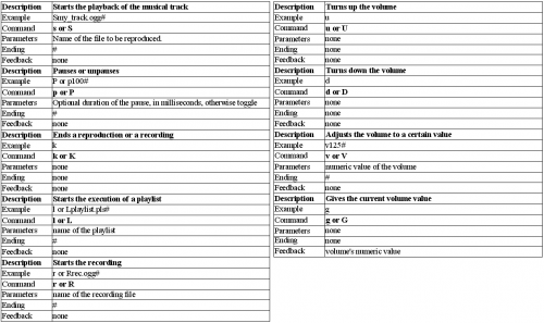
By enabling the Single Character Commands mode (with the parameter console = 2 in the conf.ini file), it is possible to interact with the MP3 reproducer in a much more compact way, to the point it will be enough to send a single character on the serial bus for each command. In some cases, as for the playback of a musical track, the commands need a string that identifies the name of the file to be played: this one may be consecutively sent to the command byte by using as a termination indicator the jolly character ‘#’. The list of the compact commands (available in SCC-mode) can be analyzed in table, while as follows it is shown how to reproduce the file named “track(1).mp3”, how to pause it and at a later stage how to stop the execution, by sending just 16 bytes:
| Strack(1).mp3#PK |
Table Description of the commands accepted in SCC mode.
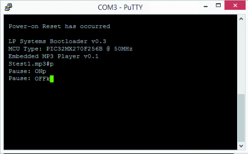
At this point we have to explain that if the console parameter in the Console section of the conf.ini file is set to 2, each byte received by the reader will be sent in echo to the sender, vice versa by setting console to 1 and verbose to 0, the device will remain silent, and will send only the possible bytes that characterize the commands with reply values that are not null.
View of an interaction simulation in SCC mode.
USAGE IN I²C MODE
In the previous paragraphs and in the previous episode we saw the list of the extended or compact commands, that can be given by means of a serial UART or USB connection, respectively in CLI or SCC mode. In this section we will pay attention to the I²C interaction mode.
In many cases, the availability of UART peripherals or of microcontrollers having USB Host capabiliy is very limited: for this reason, we thought to extend the capability to our reader, by allowing to create some I²C based connections. As for the UART or USB case, the number of IOs required remains 2, but being I²C a shared bus communication, it allows to connect the same bus to more devices, saving the number of IOs required by the pilot device.
The interaction with the Embedded MP3 is of the byte oriented command-reply kind. We know from different articles in which the I²C bus was widely discussed, that this last one is characterized by the usage of just two lines (data and clock), shared by all the devices participating to the communication (master or slave without distinction). The start and the ending of a valid communication sequence is characterized by two particular conditions, typically indicated with S (start sequence) and P (stop sequence). The communication is managed by the master that may individually query, at his discretion, the slave units that are interfaced to the shared bus.
The start sequence is followed by the sending of the first byte, that represents the physical address of the slave device, with which we want to establish a communication, this address is typically characterized by 7 bits dedicated to the address and 1 bit (LSB) corresponding to the writing action (0) or to the reading required (1); the following exchanged bytes may freely represent some generic data, or take on a particular meaning, in the case in which on the queried device some protocol based on command sending is implemented. In this specific case, we defined a protocol based on the sending of appropriate commands, with or without additional parameters.
Each command is composed of at least 3 bytes, always begins with a start sequence, and may end with a stop sequence or with a new start (sometimes called re-start). To the 3 mandatory bytes respectively correspond the physical address of the queried device, the command length and, finally, the out-and-out command. The sending of the first 3 bytes implies 3 possible scenarios of alternative evolution:
- the command sent does not consider optional parameters and may be considered as concluded, the software analyzes the length declared by the master unit and compares it to the number of bytes that have been actually received, considering the command as concluded when the condition is met. In this scenario, a conclusive stop or re-start sequence may be indifferently sent;
- the master unit sends the optional parameters (bytes) and ends the command with a stop or re-start;
- the command needs the reading of the answer generated by the MP3 reader, afterwards it is possible to send a re-start sequence and to conveniently query the device (R/W bit with a high setting).
The sending of a command happens by setting the R/W bit (a bit that is less significant of the byte address) at a low logic level, that is to say, compared with the I²C specifications, a writing operation in the memory of the MP3 reader is performed. On the other hand, to receive a command reply one has to impose a high R/W bit: this represents a reading operation, compared with the specification imposed by the I²C.
To know the result of a command, the correct sequence to follow will be: start-sequence, physical address with high LSB (W/R), the reception of the first byte immediately available (that will represent the number of bytes that are available for reading or 0, if the command is still being processed), the reception of the following n bytes and finally, the stop-sequence. We have to point out that the reading operation, without having given an appropriate command, will generate a byte-length equal to 0, with the objective to indicate an incoherence, in the case in which more data is being read.
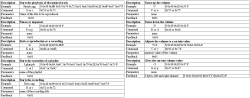
Table represents all the possible commands to give via the usage of the I²C bus, and are represented in hexadecimal format.
Table Description of the commands that are accepted in I²C mode.
Below we will show some examples of interaction in I²C mode, by stating once again the bytes sent or received, in hexadecimal format.
The first example consists in starting the playback of the “track.ogg” file, in the insertion of the pause and, finally, in the request to end the current playback. The ‘S’ e ‘P’ characters represent respectively the start and stop sequences, required by the I²C protocol.
| S 0x40 0x0B 0x53 0x74 0x72 0x61 0x63 0x6B 0x2E 0x6F 0x67 0x67 P S 0x40 0x02 0x50 P S 0x40 0x02 0x4B P |
Each command is composed by the start sequence, by the 0x40 address with a hard coded association to the MP3 reader, by the length of the data sent, in bytes (the value is given by byte-length + byte-command + byte-option(s)), by the command and possible options; for example, the command with ‘k’ ending does not require additional parameters and will have the value 2 as byte-length.
This last example shows how to request the value of the current volume and how to set it to 10, afterwards. With the ‘R’ character, we will indicate a reading operation, on the part of the master unit of the I²C bus.
| S 0x40 0x02 0x47 P S 0x41 R R R P |
The byte indicating the length of the command corresponds to the first ‘R’, if the value is 0 one must wait and try again by sending the S 0x41 R sequence, on the other hand, when the length is different from 0, it means that it is possible to continue reading n bytes from the memory. In the case of the ‘G’ command to obtain the value of the current volume, the correct length of the reply will be 0x02 to indicate that 2 bytes may still be read, corresponding to the value of the left and right channel.
Finally, we relate the final part of the example, which is needed to set the volume at a certain value:
| S 0x40 0x04 0x56 0x0A 0x0A P |
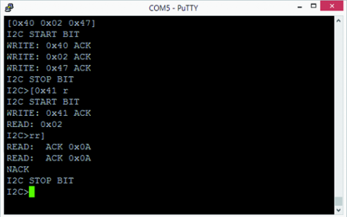
View of a usage test of the I²C mode, via the Bus Pirate. This last one is an open source component that allows to simulate the behaviour of buses or main peripherals such as the I²C bus in this specific case. In the figure, the current volume value is requested, corresponding for both channels to 10 pts.
THE SOFTWARE
In this paragraph we will deal with the description of the software and of the development environment used to create the project’s firmware. As regards the development environment, we updated our Integrated development environment (IDE) to the last version available when writing this article, that is to say the v2.15 version by MPLAB-X. Once the self-installing file has been obtained and the installation has been started, it is enough, at the end of the guided procedure, to carry out the import of our project to be able to navigate and examine the code that we created, as in figure.
View of the MPLAB-X environment and of the Embedded MP3 Player & Recorder’s project.
To be able to compile the project it is instead needed to have the MPLAB-XC32 v1.31 compiler (or a superior one) installed. We remind that with the current v1.32 version it is needed to launch the gcc with the -D_SUPPRESS_PLIB_WARNING option, to hide the warnings being generated by the compiler, whose purpose is to notify the developers that since the future versions of XC32, the library functions will be available only via the usage of the midlware Microchip Harmony (at the moment, still an experimental version). Even a compiler such as MPLAB-X can be freely downloaded and used as a minimal or trial version, to evaluate the complete version. To compile our project it is needed to use the –Os optimization, thus the free, minimal version might not be suitable for the purpose.
At this stage we may go on with the analysis of the developed code. Going in order, we find the Listing 1.
Listing 1
while (1) {


// Service the WDT

ClearWDT();


// Manager of the console routine

if (config.console.console == CLI_MODE)

   CliHandler();

else

   SCCHandler();


// Manager of I2C commander receiver

I2CHandler();


// Manager of the recording routine

if (play == PLAY_IDLE)

   rec = RecordTaskHandler();


// Manager of the player routine

if (rec == REC_IDLE)

   play = PlayTaskHandler();


// BlinkLed

if (play == REC_IDLE && rec == PLAY_IDLE) {

   Toggle1Second();

}


// // USB printer handler

// if (isUSBEnabled())

//    USBPrintTaskHandler();


// GPIO Output Task handler

GPIOOutputTaskHandler();

// GPIO Output Task handler

GPIOInputTaskHandler();


#if defined(USB_POLLING)

// Check bus status and service USB interrupts.

if (isUSBEnabled())

   USBDeviceTasks(); // Interrupt or polling method.  If using polling, must call

// this function periodically.  This function will take care

// of processing and responding to SETUP transactions

// (such as during the enumeration process when you first

// plug in).  USB hosts require that USB devices should accept

// and process SETUP packets in a timely fashion.  Therefore,

// when using polling, this function should be called

// regularly (such as once every 1.8ms or faster** [see

// inline code comments in usb_device.c for explanation when

// "or faster" applies])  In most cases, the USBDeviceTasks()

// function does not take very long to execute (ex: <100

// instruction cycles) before it returns.

#endif


if ((USBDeviceState < CONFIGURED_STATE) || (USBSuspendControl == 1)) {


} else {

   // USB printer handler if the USB cable is connected and correctly enumerated

   USBPrintTaskHandler();

   CDCTxService();

   MSDTasks();

}


}
In which to find the heart of the application. The whole software has been created with a cooperative multitasking approach, that is to say, the processor apparently carries out more duties at the same time, and the release of the CPU on the part of the single routines happens under the strict control of the same routines, in fact there is no preemptive mechanism, thus if on a side this conservative approach allows to create an efficient software, on the other hand in the case one routine does not run correctly, the whole project will enter a stall. To avoid such dangers (only a hard reset is capable to unblock the CPU from waiting an infinite event) it is good to adopt some defensive mechanism, for example by using the Watch Dog Timer. In our software we set a WDT drop equal to some seconds of time, so that the application wil be reset at the initial condition, in the extreme case in which the undesired stalls happen.Actually, we have to point out that it is not completely true that all the software is lacking preemption, in fact the interrupt routines (that are dedicated, for example, to the asynchronous timers or to the interaction with the external environment by means of buses such as: I²C, SPI, UART, USB, etc.) enjoy the possibility to temporarily interrupt a normal routine and to carry out a special duty (possibly of the duration of a few instructions). An example of interrupt management can be found in the Listing 2,
Listing 2
void __ISR(_UART2_VECTOR, ipl5) IntUart2Handler(void) {

    if (INTGetFlag(INT_U2TX) && INTGetEnable(INT_U2TX)) { // transmit buffer empty
        while (UARTTransmitterIsReady(UART2) && tx.put != tx.get) {
            UARTSendDataByte(UART2, tx.buff[tx.get]);
            tx.get = (tx.get + 1) % SER_BUF_SIZE;
        }
        if (tx.put == tx.get)
            INTEnable(INT_U2TX, INT_DISABLED);
        INTClearFlag(INT_U2TX); // buffer is ready, clear interrupt flag
    }

    if (INTGetFlag(INT_U2RX) && INTGetEnable(INT_U2RX)) { // something in the receive buffer
        while (UARTReceivedDataIsAvailable(UART2) && ((rx.put + 1) % SER_BUF_SIZE) != rx.get) {
            rx.buff[rx.put] = UARTGetDataByte(UART2); // store bytes in buffer
            rx.put = ((rx.put + 1) % SER_BUF_SIZE);
        }
        INTClearFlag(INT_U2RX); // buffer is empty, clear interrupt flag
    }
}

WORD UartWrite(CHAR8 *buffer, WORD count) {

    int i;

    for (i = 0; i < count; i++) {
        // Wait so that the buffer has at least one empty position
        while (((tx.put + 1) % SER_BUF_SIZE) == tx.get) {
            Nop();
            if (!INTGetEnable(INT_U2TX))
                INTEnable(INT_U2TX, INT_ENABLED);
            else
                INTSetFlag(INT_U2TX);
        }
        tx.buff[tx.put] = buffer[i];
        tx.put = ((tx.put + 1) % SER_BUF_SIZE);

        if (i == (SER_BUF_SIZE - 1)) {
            if (!INTGetEnable(INT_U2TX))
                INTEnable(INT_U2TX, INT_ENABLED);
            else
                INTSetFlag(INT_U2TX);
        }
    }

    if (!INTGetEnable(INT_U2TX))
        INTEnable(INT_U2TX, INT_ENABLED);
    else
        INTSetFlag(INT_U2TX);

    return i;
}


WORD UartRead(CHAR8 *buffer, WORD count) {

    int i = 0;

    while (rx.put != rx.get && i < count) {
        buffer[i++] = rx.buff[rx.get];
        rx.get = ((rx.get + 1) % SER_BUF_SIZE);
    }

    return i;
}
In which the bytes passing on the UART are managed in a transparent way, as opposed to the normal execution of the software: this is obtained by using a circular buffer that is emptied or filled in an asynchronous way in respect to the ongoing process, that is to say, by generating the appropriate interrupt signals, and later by returning the control to the interrupted method. By adequately using the interrupts on the hardware events, and by using an appropriate subdivision in tasks, in microactivities that are not too long, it is possible to succeed in obtaining a good and competitive system, one that does is not affected by the absence of an operative system, even when there are many tasks to manage. It stands to reason that the software created for the correct operating of the player is very extended, specially in the CLI interaction, this is why we tried to comment abundantly all the sources of the project, thus avoiding to make the reading of the article heavier with the usage of very extended listings.

