
We built a small musical instrument that will delight children and will allow them to play 8 notes and shift their frequency as desired using a potentiometer.
Projects like the laser harp published in the previous post have accustomed us to seeing challenging circuits based on synthesizers and microcontrollers to produce musical notes, yet even before all this was born the sounds were synthesized and generated without resorting to too much electronics and with a handful of components. You have the proof of this by reading the following pages, where we publish the project of a simple musical instrument that we can consider an electronic remake of the bagpipes, as like the popular and very ancient instrument, moreover firmly anchored to the Christmas tradition; it allows to make to shift some notes in tonality while you are playing it.
This small circuit, within everyone’s reach, because it is essential, economical and easy to make, can become the first musical instrument for a child or a pleasant gadget to accompany the end-of-year parties with music.
ELECTRICAL PLAN
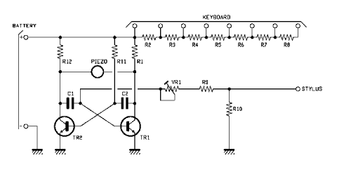
Let’s go now to see what it is, analysing the circuit that creates the musical instrument, which is essentially a multivibrator as an NPN-type BJT, to which we have added a piezo buzzer (without electronics, because it will be driven by the variable signal produced by the astable itself) and a trimmer so as to alter the frequency by moving it even an octave. Thanks to a scale of resistances and to a wire that we make to touch on eight pads corresponding to the union nodes of the resistances of the aforesaid scale, we can set the astable multivibrator to let it generates as many notes, simply by tapping the pads that in the wiring diagram are grouped under the heading KEYBOARD with a wire connected to the STYLUS point.
Anyone who wants to can make the little instrument more practical to play by creating a real keyboard, which could simply be composed of eight normally open buttons, joined at one end and with free contacts, each connected to one of the KEYBOARD pitches.
The circuit is a rectangular signal generator since it cannot maintain a stable state and its transistors switch continuously and one as an alternative to the other, making sure that TR1 and TR2 always present opposite levels.
This phenomenon starts when the circuit is powered, when, although both capacitors are discharged, the transistor which has a lower threshold voltage enters first and blocks the other, at least until the capacitor connected to the base of the latter does not load.
To understand the operation of the circuit we first study that of the astable multivibrator which is its heart, starting from the consideration that it can work, although it is theoretically composed of two symmetrical transistor stages, due to the fact that two BJTs, albeit of the same model, have slightly different characteristics and such that, in the instant in which the circuit receives the power supply, one of the two enters in conduction first conditioning the other. In fact, in the astable, the conditions of the two transistors that compose it are intertwined and one influences the other.
For our study let us suppose that the STYLUS contact is connected to one of the resistances R2, R3, R4, R5, R6, R7, R8 and that in the instant in which we apply voltage to the circuit through the + and – BATTERY points, we enter into conduction first TR1; as a result of this, the collector of the latter goes to about zero volts (by grounding the armature connected to it of the capacitor C1) and in any case is a potential that does not allow the polarization of the base of the TR2, since the current of the TR1 collector causes a drop in value in the resistance R11 such as to keep the Vbe below the threshold value. This is because C2 is initially uncharged and passes current.
In this condition, TR2 remains off and via R11 the capacitor C2 starts to charge until the base of T2 is at a potential such as to saturate this transistor, and then the base voltage of the TR2 is lowered below the threshold voltage and the same TR2 is inhibited.
Now it is the collector of the TR2 to go to logic zero and download C1, providing at the base of the TR1 a low-level pulse that carries the same transistor in interdiction, which means that the collector of this BJT moves to a high level. Now C1 begins to load and at a certain point brings the base of TR1 to a potential such as to cause again the conduction of this BJT, whose collector returns to zero volts and causes C2 to discharge immediately, which gives a low-level impulse on the base of the TR2, making it interdict.
The described cycle is repeated until the circuit remains powered and leads to the production of two opposing phase rectangular waves on TR1 and TR2, therefore by connecting the PIEZO buzzer between the two collectors we obtain a variable, or alternate, waveform signal rectangular and of theoretical amplitude equal to twice that of the pulses present between the collector and emitter of the transistors. An amplitude of sufficient value to drive the piezoelectric pad located inside the buzzer and to make it emit an acoustic vibration intense enough to be heard at the right level in the surrounding environment and in any case just enough to satisfy the needs of a person who is playing the little instrument.
The duration of the charge and discharge cycles of the rod’s capacitors determines the frequency of the note reproduced, in the sense that the latter is valid:
f = 1/ (t1 + t2)
where we call t1 the duration of the permanence of the high level on the collector of the transistor TR1 and therefore of the charge of the capacitor C1, while with t2 we mean the duration of the high level on the collector of the other transistor (TR2) and of the charge of C2. In turn, the cycles depend on the resistance and capacitor values involved, then R11 for C2 (t2) and the sum of R9, VR1 and that, between R2 ÷ R8 connected by the wire starting from STYLUS (we refer to the charge of C1 and then at time t1). In truth in the determination of the interval t1 the ratio between the inserted resistance R2 ÷ R8 and R10 is also included, but let’s take it as well that this is not very relevant, otherwise the calculations would be complicated, also because then we should also understand the effect of the base currents of TR1 and TR2.
However the maximum calculation is the one proposed by the formula, from which we see that being t2 conditioned by the values of the inserted resistances, we can obtain from the buzzer as many frequencies as there are notes plus one, so 8: there are this many musical notes composing an octave, or DO, RE, MI, FA, SOL, LA, SI, DO.
It is understood that the exact frequencies are obtained by tuning the instrument with something similar to those instruments for tuning guitars; the classic tuning fork is not good, because it typically emits the note LA higher than the central DO (for central means that of the central octave of the piano keyboard, which has 88 keys divided into three keys on the left, 7 octaves and a further DO a right) which conventionally sounds at 440 Hz but you can use a tuner whistle. In our case, since the minimum reproducible frequency is of the order of 580 Hz something is needed that sounds at a higher or equal frequency.
The arrangement can be performed with the VR1 trimmer, which is mounted as a rheostat allows to vary the resistance that puts in series to the charge circuit of the capacitor C1 and, more precisely, to increase it by moving the cursor to the base of the TR1 (the increase corresponds to the elongation of the time t1 and therefore the lowering of the tone of the notes) or to decrease it if the cursor moves in the opposite direction (the frequency reproduced rises because t1 shortens).

Finally, note (and you can check it out by playing the instrument) that the note reproduced by our small musical instrument is all the more acute the closer the STYLUS is connected to the positive power supply, i.e. the note becomes more serious as it passes from the R1-R2 node to the R2-R3, up to the free end of the R8, a condition which corresponds to the lowest note.
Since we are on the subject of frequencies, the minimum reproducible (connecting STYLUS to the free end of the R8 resistor and with the RV1 trimmer all inserted) is about 580 HZ, as just explained, while the maximum is of the order of 2,400 Hz: in this case we are in the condition of RV1 short-circuited and STYLUS connected to the positive power supply.
In summary, the lowest range of notes ranges between 580 (note relative to the left-most pad of the PCB) and 1,680 Hz (note relative to the rightmost pad) bringing STYLUS from the positive power supply to the free end of R8 and corresponds to RV1 all inserted; The sharpest, on the other hand, ranges from about 990 Hz (pad left) to 2,400 Hz (pad right) and corresponds to RV1 short-circuited. In the intermediate positions of the trimmer intermediate frequencies are obtained, which allows us, if we wish to do so, to slip the note (Pitch Bend function) while we play it, a bit as we do with the guitar distortion.
FROM OPENSTORE
