
[bctt tweet=”A shield for the acquisition of 8 analog signals from the Raspberry Pi board.” username=”OpenElectronics”]
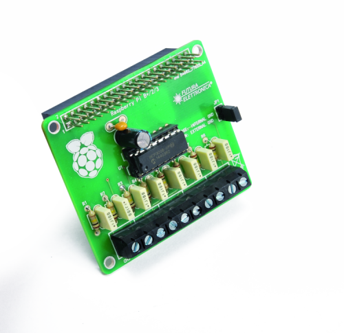
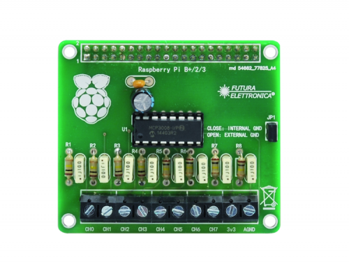
A shield for the acquisition of 8 analog signals from the Raspberry Pi board, which can be stacked with other boards in order to, for instance, interface a big quantity of sensors, diagnostics, environmental control and IoT applications.
The popular Raspberry Pi board has recently come to its third edition: it is a powerful core to develop every kind of application, even quite demanding ones. Besides the standard communication port equipment, it adds a series of GPIOs that can be accessed by the expansion connector, allowing (especially the data channels such as the 4-wire SPI) to hugely extend connection possibilities to analog and digital devices. In the past, we had already proposed a (so-called) expansion shield with digital inputs/outputs managed by the I²C-Bus and today we want to follow up on that subject with something similar, although specifically dedicated for the acquisition of analog voltages. It is a shield designed to be applied to the expansion connector of Raspberry Pi 3, which hosts the 2,54×2,54 step female connector on one side, ideal to be paired to Raspberry Pi’s connector, while on top has double row pin strips for repeating connections, in order to make them available to other circuits and possible additional shields that might be required by some applications.
With that said, let’s get to the core part of the project starting now from circuit analysis, which will explain hardware composition and functionality; we will later describe the software side and specific configuration.
The diagram
The shield we propose you is an expansion model for Raspberry Pi based on the MCP3008 IC, i.e. a 10-bit analog-digital converter that can be connected to a maximum of 8 channels, each one corresponding to one of its input pins.
This IC, enclosed in a DIP 7+7 pin case, is ideal if you want to read the voltage value supplied to e.g. an analog sensor, or if you want to read voltage in a precise point of the circuit; in any case, the admitted range is between 0 and 3.3 V, so if you have a voltage with higher amplitude, it is important to adapt it to the 0÷3,3V or limited. In the first case you have to use level translators (e.g. trap circuits or attenuators composed by at least one resistive voltage divider) and in the second case by Zener diodes.
On the other hand, if you need to measure negative voltages, you have to inverse their polarity by using, for instance, an inverting Op-Amp buffer.
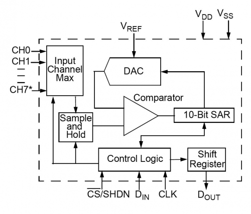
The DAC converter inside the MCP3008 has integrated sample & hold; we remind you that the sample & hold is the sampling circuit which periodically connects an input to a capacitor and then discharges the latter on the ADC input, in order to save it from sudden voltage variations. The sample & hold is basically a sampler, that is a circuit taking signal samples of pre-fixed duration, typically using two couples of solid-state switches opening and closing alternative (when the input switches are open the A/D converters are closed and vice versa).
MCP3008 inputs can be cyclically assigned to the sample & hold and then read by the actual ADC and can be configured both as single-ended outputs (on balance, just like in our application) or in couples, by creating a pseudo-differential mode.

The SPI interface of the integrated circuit works in 0,0 and 1,1 modes. The sampler’s sample rate is 200 ksps max at 5 V and 75 ksps max. at 2,7 V, which makes you notice how it depends on power voltage. So in case of acquisition of signals which periodically vary over time, our A/D converter can sample frequencies of around 100 kHz.
As anticipated, the measuring range is 0 to 3.3 V and it goes without saying that the more the voltage to be converted is close to 3.3 V, the more precise conversion will be, since the 10 bits, which guarantee 1024 samples, determine a voltage resolution of around 3.32 mV with the above-mentioned full-scale.
We have to point out that the measurement range depends on the reference voltage of the ADC applied to the Vref pin and in our case is limited to 3.3 V because that pin is connected to the shield’s power line; however, since the IC accepts a voltage between 2.7 and 5.5 V, we can move the reference higher and set it for instance to 5 V. It is understood that the higher Vref is, the less precise acquisition will be, since sample resolution is equal to Vref/1.024. Therefore, if you expect to acquire very weak voltages, you can lower Vref to values that are barely higher to the expected max amplitude and the inputs, therefore benefiting from the range – signal ratio, thus getting maximum possible precision. Please note that Vref can also be received by LDO regulators (in order to obtain a stable reference) at very low output voltages, which can be easily found on the market today; for instance, using a LM1117 by Texas Instruments, available in with fixed output voltage of 1.8V – 2.5V, 3.3V, 5V and in ADJ, or using a LTC3025 by Linear Technology, which accepts 0.9 to 5.5 Vcc as input and allows to regulate output voltage as far as 0.4 – 3.6 V, or using a LT3007, which is another LDO available in various versions with output voltages starting from 1.2 V.
The shield proposed in this article has been specifically designed to be used with Raspberry Pi version 3, which is completely devoid of ADC ports. In order to make up for this lack, the shield can be mounted on the 40-way expansion connector of Raspberry Pi 3, thus obtaining 8 onboard analog ports which signals, when duty digitalized in 10-bit format, will be acquired by taking advantage of the hardware SPI port of Raspberry Pi itself, in a way we will explain later.
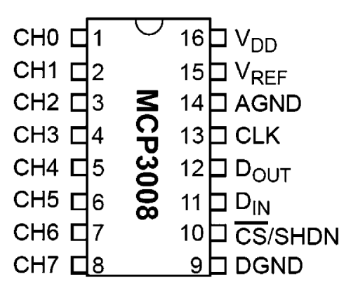
To help you understand the circuit diagram, the figure shows the pin-out of the MCP3008 integrated, produced by Microchip.
As anticipated, the integrated circuit must be connected to the Raspberry Pi through the SPI port, however, we could also take advantage of a software SPI, by connecting pins CLK, DIN, DOUT and CS to any other pin of the raspberry board.
In our case, using the hardware SPI port, the integrated circuit will be connected to his 19, 21, 23 and 24 of the connector. In the circuit diagram you can see how the Raspberry Pi interfaces with the MCP3008 integrated: we are using the SPI bidirectional channel, for which MOSI (Master Output Slave Input) is the output of Raspberry Pi and the U1’s data input, MISO (Master Input Slave Output) is the input through which Raspberry Pi receives digital data from the ADC, CE0 is the Chip Enable activate and deactivating U1 and CLK is the clock for full-duplex serial communication. MOSI is then used by Raspberry Pi to control MCP8003 and MISO to acquire readings. Please note that on each input channel we have provided a RC network that allows to stabilize value read by the ADC, since after lab tests have shown that value read by the ADC on a free input is not really stable, while this way, with no signal on the input we would have a perfect “0” because the resistor acts as pullout and the capacitor acts as a filter for impulsive disturbances captured by the circuit or by the connection wires.
Please also note that we have considered a bridge labeled JP1, allowing to decide if you want to use the circuit’s internal ground or the external ground as a reference. If the bridge is closed, the reference will be the shield’s internal ground, therefore you will only have to connect the sensor’s output to the input and power for the sensor will be taken by the circuit itself, using the “AGND” and “3,3V” terminals.
However, when you have sensors with their own ground because they come from a different circuit, you can leave JP1 open, but in this case, the ground of the second circuit must be connected to the shield’s AGND terminal.
Same goes if you have to acquire voltages coming from a circuit with a different ground than the shield.
Library
All the controls for the ADC shield for Raspberry Pi has been sourced from a library already made by third parties; this way we could use the library right away without major issues, thanks to the possibility to directly install it in the Linux operating system loaded on Raspberry Pi.
The library provides both hardware and software SP1 library management. For going in depth in the library and explain how to install it, we are listing the pins already provided in the library and specific for the application, so that you can build the hardware around those pages, without the need for major interventions on the library code.
SPI Software
MCP3008 CLK > Raspberry Pi GPIO18
MCP3008 DOUT > Raspberry Pi GPIO23
MCP3008 DIN > Raspberry Pi GPIO24
MCP3008 CS/SHDN > Raspberry Pi GPIO25
SPI hardware
MCP3008 CLK > Raspberry Pi SCLK
MCP3008 DOUT > Raspberry Pi MISO
MCP3008 DIN > Raspberry Pi MOSI
MCP3008 CS/SHDN > Raspberry Pi CE0
Library Installation
First, you have to load the operating system on the Raspberry Pi board.
To this regard, remind you that you can download the image for the desired system directly from the website https://www.raspberrypi.org in the “Download” section.
Among the operating systems proposed for Raspberry Pi on the website, we recommend NOOBS or Raspbian, since they fit perfectly without major issues to the terminal execution in order to install and manage the library for our shield.
After creating the SD and launch the operating system, we can proceed with the download and install Adafruit library through GitHub.
First, you have to make sure that Raspberry Pi has an Internet connection, by simply opening the browser and trying to browse the web. If you can do that, then you will open the terminal and type commands in the following sequence, followed by “enter”:
- sudo apt-get update
- sudo apt-get install build-essential python-dev python-smbus git
- cd ~
- git clone https://github.com/adafruit/Adafruit_Python_MCP3008.git
- cd Adafruit_Python_MCP3008
- sudo python setup.py install
The library installation should proceed without any issues, however, in case of errors, we suggest you try and execute the command again or repeat the above procedure from the beginning.
The figure shows the screen with the given commands, everything was successful.

Using the library
Once the installation is done, you can open the example included in the library itself, this way you will have the chance to edit its configuration and immediately try to read the MCP3008’s channels.
Once again from the terminal, input:
- cd ~/Adafruit_Python_MCP3008/examples
- nano simpletest.pyThe commands above will open the “simpletest.py” example in edit mode. This way you will have the chance to decide which SPI to use (hardware or software); then, scroll down in the page until you find CLK, MISO, MOSI and CS declarations.
These are the declarations for using the software SPI, therefore if you want to use this one, you don’t need further modifications; on the contrary, if you want to use the hardware SPI port, you will need to comment on lines 2, 3, 4, 5, 6 in the example below, putting a “#” in front of every line, while you will have to leave out that symbol from the lines related to the hardware serial such as SPI_PORT (line 8), SPI_DEVICE (line 9) and mcp (line 10):
- # Software SPI configuration:
- CLK = 18
- MISO = 23
- MOSI = 24
- CS = 25
- mcp = Adafruit_MCP3008.MCP3008(clk=CLK, cs=CS, miso=MISO, mosi=MOSI)
- # Hardware SPI configuration:
- # SPI_PORT = 0
- # SPI_DEVICE = 0
- # mcp = Adafruit_MCP3008.MCP3008(spi=SPI.SpiDev(SPI_PORT, SPI_DEVICE))
In our case, the SPI to be used if the hardware one since this is the one called for by the circuit diagram, therefore the resulting code will be:
- # Software SPI configuration:
- #CLK = 18
- #MISO = 23
- #MOSI = 24
- #CS = 25
- #mcp = Adafruit_MCP3008.MCP3008(clk=CLK, cs=CS, miso=MISO, mosi=MOSI)
- # Hardware SPI configuration:
- SPI_PORT = 0
- SPI_DEVICE = 0
- mcp = Adafruit_MCP3008.MCP3008(spi=SPI.SpiDev(SPI_PORT, SPI_DEVICE))
After the necessary modifications, you can’t save to file by pressing “Ctrl-o” and then “Invio” to save the file, then “Ctrl-x” to exit.
Now that the fight has been saved you have to input, still from that terminal, the following string in order to execute the example you have just edited and allow for analog ports reading.
sudo python simpletest.py
As shown in the figure, this will launch the simple test program that allows reading all the 8 channels of the A/D converter.
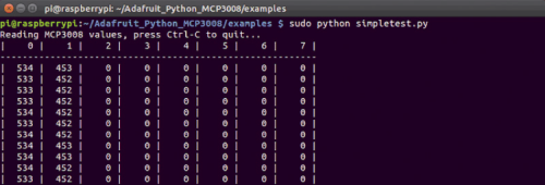
Usually, if nothing is connected to the input, you should see “0” on each channel, or a different value resulting from analog/digital conversion if you have a sensor connected to the input or a signal applied to it.
Warning: please remember that voltage applied to the shield’s input cannot be higher than 3.3 V, otherwise the integrated ATC would be damaged. Since the limit is 3.3 V (established by VREF which is on the level with power voltage) the commercial result but said voltage will be 1.023, i.e. each point of the conversion will equal to around 3.22 mV.
For instance, if you take a look at the example below, value 534 will correspond to 3,22 x 534 = 1.719 mV while value 452 will correspond to 1.455 mV.
If, for instance, you want to run a quick test to check if the conversion is correct, you will take a potentiometer, which center is connected to a channel among the 8 available, while the two terminals are connected to 3.3 V and the other one to GND, then we will rotate the cursor: you’ll see the constant variation of value resulting from A/D ranging from 0 to 1.023.
In the example shown in figure age, represents a channel (0 – 7), while each row shows the sampling results, then the results of the conversion operation.
To execute the text program, you must press “Ctrl + c”.
In order to better understand the code’s logic, therefore how conversion takes place, we can examine the code section in List 1, which she’s the section included in the “simpletest.py” program we have created.
The code is quite simple and all it does is sequentially reading the 8 inputs (0 – 7) through the command:
values[i] = mcp.read_adc(i)
Which recalls read_adc() function from the MCP3008 library, which will return the value corresponding to the conversion for each one of the inputs, associating it with the related input number.
Listing1
1. print(‘Reading MCP3008 values, press Ctrl-C to quit...’)
2. # Print nice channel column headers.
3. print(‘| {0:>4} | {1:>4} | {2:>4} | {3:>4} | {4:>4} |{5:>4} | {6:>4} | {7:>4} |’.format(*range(8)))
4. print(‘-’ * 57)
5. # Main program loop.
6. while True:
7. # Read all the ADC channel values in a list.
8. values = [0]*8
9. for i in range(8):
10. # The read_adc function will get the value of the specified channel (0-7).
11. values[i] = mcp.read_adc(i)
12. # Print the ADC values.
13. print(‘| {0:>4} | {1:>4} | {2:>4} | {3:>4} | {4:>4} | {5:>4} | {6:>4} | {7:>4} |’.format(*values))
14. # Pause for half a second.
15. time.sleep(0.5)
Okay, this is all; now, it’s your turn to create any applications you desire and integrate library in your software. If you are up to the challenge, you can develop your own specific library starting from our library.
Enjoy!
From openstore
8CH ADC Shield for Raspberry Pi
Raspberry Pi 3 Model B with Wi-Fi and Bluetooth
Integrated 10 bit serial Analog / Digital converter

Hello, PCB design files are available ? Also values for RC filter ?
Thank you,
Daniel