[bctt tweet=”CUTTING PLOTTER FOR POLYSTYRENE creates shapes of every kind, carving them hot, starting from polystyrene foam or sheet and other materials with low melting temperature. Let’s use it to make Christmas decorations and find out how useful it is in a thousand applications” username=”OpenElectronics”]
It is not a long time since we have presented our latest creation about 3D printing (the beautiful 3D4040) but we desire to come back to the subject by proposing something that it is like a 3D printer, although even printing solid, strictly speaking, it’s a 2D machine. To be precise, the P400 (this is the name) is a CNC cutter, a machine that works removing material; you can also get three-dimensional objects by making 3D puzzles. In addition to it is possible to build perfect shapes to be used as Christmas decorations, such as trees, snowflakes, ribbons, boxes, two-dimensional balls, but also box letters, logos, symbols, 3D puzzles, etc.
The P400 is a CNC machine that can work with poor and easy to find materials, waste materials for someone, they become a blank sheet on which to express the imagination for others. This is the spirit of the machine (and of the polyshaper technology on which it is based, better described on www.polyshaper.eu) that we present.
The idea of a polystyrene CNC cutter also comes from the fact that polystyrene is an economic and widespread material, everyone has some piece in the house.
The P400 is a CNC machine so it is controlled with the classic G-code commands, just like all these kinds of machines.
The P400 is a machine with small dimensions (550x550x200 mm), thanks to its fast and precise cuts it allows to realize several creations; the limit is just the imagination, the machine makes even possible to create complex objects composed of several parts connected together. The cutting speed is significantly higher than the depositing rate of a 3D printer, the possibility of making multiple cuts in parallel and the download of several files ready to use from Internet make the project even more attractive. Furthermore, you do not risk much if you accidentally make a mistake or accidentally interrupt the cutting: you are using cheap polystyrene, not the expensive PLA and ABS of 3D printing…

TECHNICAL SPECIFICATIONS
- Working area: 400×400 mm
- Working depth 60 mm
- Resolution: 0.5 mm
- Tolerance X Y: 0.012 mm
- Cutting speed: 1 m / min
- Cutting technique: hot wire
- Working materials: low temperature melting foam
- Power supply: 12V
- Adjustable thread temperature
- Management from PC via USB interface
THE PROJECT
The P400 cuts the polystyrene with the hot wire technique. The structure is very simple and light, the total weight does not exceed 3.5 kg. One of the advantages of cutting the polystyrene in this way is that the wire just touches the polystyrene, so there is no need for a robust mechanism. The frame is made of grooved sections, on which all the components are assembled, two wishbones arranged orthogonally to each other are created with the ground-round bars. The fixing mechanisms allow creating the two orthogonal sections of the machine. The movement is entrusted to the ground-round steel bars 50 cm long on which flow the linear bearings that allow the movement of the upper wishbone on the lower one.
The movement, thanks to the small dimensions and light weight of the machine, is achieved through a system of toothed belts and pulleys that allows, through a simple and robust mechanism, the movement on the two axes. The reduced length decreases the backlash due to the elasticity of the belts themselves, thus reducing the risk of loss of step. The frame is made by a central section 50 cm long, on the ends two pieces (orthogonal profiles) 150 mm long are fixed with the aid of two corner brackets screwed on each side, so the structure is stiffer. Parallel to the central section we have the two steel bars, which act as guides for the upper portal, they have the same length as the central section and are locked to the crosspieces thanks to special elements. The structure is so slender and light and the low stiffness required means that a central crosspiece is not necessary to close the upper wishbone which is ideally delimited by the imaginary line between the bearings. The upper frame doesn’t have to carry any load, so it is made simply by the ground-round bars 50 cm long.

The movement of the “print” head that supports the hot wire used to cut the foam is made by two toothed belts that transmit the motion of the stepper motors. The belts passing through gears and pulleys are kept always in tension, to avoid jumps and leaks; the belts work with traction and therefore must adhere well to the toothed pulleys of the motors.
Two motors are mounted on the machine, one of which is applied to one end of the frame (machine zero on the horizontal axis …) and moves the vertical portal from one end to the other. The second motor has the task of moving the wire. The step motor is placed to keep the center of gravity of the structure as low as possible and therefore make the machine more stable. This factor is very important because even if the masses are reduced compared to other CNCs with more consistent end-effector (head), the speeds and accelerations are higher. This increases the reduction of processing times, which in the P400 are really very low.
The stretched hot wire slides through the two slides placed on the vertical guides; the synchronism of the two sides is obtained through the toothed belts that keep the wire perfectly horizontal. The electric power, carried by a pair of wires, passes through the upper crosspiece. It becomes essential to isolate it from the rest of the structure which is at neutral potential, so the wire is separated from the structure thanks to special insulators. The polystyrene sheet is locked thanks two special latches which move along the main frame section, to insert sheets of different lengths. The tightening is done through a special guide.
THE ELECTRONICS
The P400 that we propose is particular version where the electronics is still based on Arduino, but the control board is the 3DCONTROLLER used for the 3Drag printer with only two drivers, the Pololu type A4988, which are used to control the two motors (X and Y axes) so the movement of the wire in the plane to cut the expanded polystyrene. The drivers are based on the integrated A4988 (Open electronics code 3DDRIVER) and are therefore the same as the 3Drag, they support the microstep mode. They are connected to the X-MOTOR and Y-MOTOR connectors (the others are free). We are not describing the wiring diagram of the controller and the driver module, but we refer to the article proposed in file 175, where they were presented and described in detail. All you need to know is that the driver modules are set to 1/16 microstep mode.
The stepper motors are NEMA 17, powered by 12 volts.
The power supply for is a small 12 volt 5A power supply that can work with 230V or 110V. Due to the structure, the simplicity and the lightness of the machine, even when cutting, the motors absorb low power. The power supply supplies power to the motors and to the cutting filament thanks a step-down voltage regulator with variable output voltage. The hot wire is made of nickel-chromium alloy and must be kept to a temperature a little bit higher than the melting point of the foam used.

The cut is the result of Joule effect so the wire reaches a temperature above 190 ° C; we use a piece about 15 cm long with a diameter of 0.1 mm. The heating of the wire is generated thanks to electric current flowing through the wire:
P = V x I (error) P=R x I^2
To adjust it we use a DC / DC converter that controls the voltage at the ends of the wire going to vary the current flowing there. The stepdown instead of the potentiometer is a more efficient method to control the voltage as compared to the latter, it guarantees a higher transformation efficiency, close to 95%. Temperature control is essential for cutting, in particular it is important to give the right ratio between cutting speed and tension on the stepdown. Of course, there are several parameters that affect the temperature and the cutting speed: the density of the foam and the thickness of the wire. For example with a low-density polystyrene with large cells of 20 mm thickness we can consider 0,4 absorption amps, while if the thickness of the wire is double, going from 0.1 mm to 0.2 mm, it would be necessary to double the tension. To set these values, the stepdown used has a display and buttons to change the parameters. With very high temperature, in fact, the cut affects a very wide area around itself, this, therefore, leads to less precise cuts. The cutting speed in addition depends on the motors but is also influenced by the wire temperature: if it is too low compared to the cutting speed, the wire would not cut the polystyrene in time and breaks itself against the sheet; vice versa, a very high temperature combined with a very low speed reduces the precision, due to the cut that affects a very large area of the cells of the foam.
Software
After the hardware, we analyze firmware and software; we start from the firmware installed in the ATmega2560 microcontroller of the controller board, which is the classic Marlin, the same of the 3Drag but adapted to the new hardware with only two axes.
To manage the cutting, we use PC software:
- Inkscape (https://inkscape.org/it/) to create and edit templates;
- the Polyshaper Plugin for Inkscape (https://github.com/GIPAT-Polyshaper/PolyShaper_inkscape) to get the G-Code.
- Repetier-Host (www.repetier.com/downloads) as a print client;
The firmware used is not the same of the 3Drag: however, we used the basic configuration of the pins of the 3Drag board, modifying some parameters; so in the Marlin we find the usual
#define MOTHERBOARD BOARD_3DRAG
indicating that it is the 3Drag controller. The baud-rate of the virtual serial was set at 115.200bps with the instruction:
#define BAUDRATE 115200
In addition, some basic changes were necessary, including the deactivation of the temperature sensors, bringing the minimum temperature value to “0” so as not to generate errors and prevent the control of the machine as in this case there is no extruder, so no temperature sensor:
#define HEATER_0_MINTEMP 0
In the machine there are no mechanical limit switches, so in the firmware they have been deactivated, setting a logic that represents those of type N.O. (normally open):
#define X_MIN_ENDSTOP_INVERTING true // set to true to invert the logic of the endstop.
#define Y_MIN_ENDSTOP_INVERTING true // set to true to invert the logic of the endstop.
#define Z_MIN_ENDSTOP_INVERTING true // set to true to invert the logic of the endstop.
#define X_MAX_ENDSTOP_INVERTING true // set to true to invert the logic of the endstop.
#define Y_MAX_ENDSTOP_INVERTING true // set to true to invert the logic of the endstop.
#define Z_MAX_ENDSTOP_INVERTING true // set to true to invert the logic of the endstop.
The number of steps for each axis has been adapted to the driver in use (configured to 1/16 step) and to the number and pitch of the belt teeth. In our case, the steps for mm for X and Y have been set to 80, while for Z and extruder nothing should be specified because the Z axis does not exist. So we have this situation:
#define DEFAULT_AXIS_STEPS_PER_UNIT { 80, 80, 2560, 600 }
The firmware must be loaded into the controller via USB, starting the Arduino IDE, setting the board (Arduino Mega 2560) and writing the file to the board. After the firmware we talk about PC software: we have to install the software package needed to proceed with the first cut. The software is an editor to make the sketch of the pieces we want to cut and generates from them the G-code files to control the P400. The editor is Inkscape, a vector graphics software, which is particularly interesting not only for its several tools available but also because it is open-source. Inkscape allows to draw, create geometric shapes, import images and write in many writing styles. The possibilities are therefore endless. Download Inkscape is simple, you have to go to https://inkscape.org/ and download the version suitable for your operating system in the Download section. In this step, we show how to generate the G-code directly from Inkscape. For this purpose we use a plug-in, created specifically for this machine, called polyshaper and which can be downloaded for free from github.com at https://github.com/GIPAT-Polyshaper/PolyShaper_inkscape.
Now we can proceed to the installation by following these steps:
- Open INKSCAPE> Edit>
The window on the screen once enlarged is made by two parts;
- on the left side there is a “tree” where you have to select “system”; then in the box on the right you select “extensions” and replace the path (to see the changes you have to close Inkscape and restart it);
- download the Inkspace plugin by copying the contents of the “plugin” folder into the Inkspace user extension folder; to find the folder, check it from the Edit> Preferences menu.

Finally, it’s time to make the first cut. Let us become familiar with the program now: while the operations of sending the G-Code to the machine via Repetier-Host, are quite simple and repetitive, the use of INKSCAPE and the plug-in polyshaper take some time. However, more commands mean more possibilities, so it’s time to begin…
We start learning how to create a Christmas decoration, in particular, a ball, so we are learning how to realize part of the images shown in these pages, the rest depends on the imagination of the reader. At the link www.polyshaper.eu/2D_Project.php there are several drawings with G-codes ready to be cut; the page is updated continuously. But now, Let’s open Inkscape.
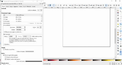
First of all, to be sure that the sketch (or writing or stencil) has measures comparable with the cutting dimensions of our machine, it is better to set the dimensions of the sheet at 400X400mm (cutting area of the machine); To do it, you move to the drop-down menu at the top left and issue the File / Properties command of the document . Clicking, you can choose the size (the default setting is millimeters, but you can change the unit of measure in the menu next to it). If the change was successful, the white sheet in the background has adapted to the dimensions entered; the ruler on the top of the sheet provides further confirmation of the change. Now it is possible to close the window.
On internet through Google Images search for “Silhouette Christmas Ball” and save the corresponding image that you can find among the downloadable files from our website. Now, from Inkscape import, the image file with the menu command File / Import then, from the pop-up opened, choose the file to be imported and confirm the settings from the window that appears.

Now you have to give the Draw bitmap command from the Path menu and, in the window that opens confirm the settings, then close the window.

With the left button of the mouse click on the imported image and, keeping the button pressed, drag the image to another point of the screen, so it will be duplicated. Now you have to enable the display of the skeleton of the image with the Skeleton command of the Display Mode submenu, accessible from the View menu. Delete the previously imported image which will now appear with a red “X” as large as the image. Instead, keep the processed image that will be completely blank with a black cutting edge. Place the image in the work plane, resizing it if necessary. Now you have to reduce the Bezier with the command Extensions / Edit path / Flatten bezier. In the dialog set the value of the Flattening box to 1.0 and confirm with Apply, then close the screen.

Now we can move the image in the work area in such a way as to minimize waste in the polystyrene sheet. Click on the object to create the cutting path and export it using the Polyshaper plug-in.

In the window opened, choose the name of the file you want to get when you have exported the G-code and choose the size of the working area (polystyrene). Set the Cutting Speed, pay attention, it also depends on the material used: thicker it is, lowers the speed must be and vice versa. The foam polystyrene foam with low density is cut with higher speeds than those of expanded polystyrene (thermal insulation sheets for building).

Once this is done, click on Apply to go to the next window, where the path to the file name appears. Take note of the path where the generated file is located, so you can open it with a G-Code reader. On the main screen, a pair of zeros appears, representing the origin of the axes, the machine zero: the physical origin of the machine is at the bottom for the vertical axis while it is located on the horizontal axis.

Well, now let’s perform the cut starting from the G-Code created: first start the Repetier-Host, then from the Configuration> Printer Setup menu select from the Connection tab the COM port associated with the machine and the baud-rate of 115,200 bps.

From the Printing plan options tab set, as a printer type, CNC Router and then set X Max and Print area width to 400; for Y Max and Print area height set the value 400.

Confirm the settings and then click on the button Connect in the menu bar and wait for the connection; note that once the connection is established, the button becomes Disconnect.

To verify that everything is working well, from the Manual Control section try to manage the X and Y axis to check the movement. Warning: do not click on the Home keys: the machine does not provide mechanical Home; also operate without a plate on the machine, otherwise, since the wire is not hot, you will damage it! If everything is correct, click on the Load button to access the dialog with which to select the file (gcode extension) created by Inkscape; Once you have chosen the file, click on Open Now you have to place a polystyrene sheet in place, then adjust the tension for the cutting wire from the display of the DC / DC regulator of the machine according to the type of polystyrene used.

During the tests with traditional polystyrene a tension between 2.7 and 3.4V was set according to the cutting thickness to be obtained. You have to be very careful because the wire must be hot enough to cut the polystyrene without straining too much; if it was difficult it would be necessary to raise the tension to raise the temperature and facilitate the penetration into the material. Now, using the Manual Control section of Repetier Host, move the X and Y axes so that the cutting line is as close as possible to the polystyrene. Click on the Start Job button and wait for the cutting to end. You can enjoy the result of your work at the end of the process, when you extract from the machine, delicately and being careful not to deform or break the hot wire, the cut piece.

Well, we said everything; we just have to wish you good fun with your creations!

From openstore
CUTTING PLOTTER FOR POLYSTYRENE
