
Building our centralized web-controlled home video surveillance system. Second episode.
In the first episode of this series, dedicated to the creation of a video surveillance system, based on Raspberry Pi and the MotionEye application, we saw how to install the software necessary for our architecture and how to configure a first video camera connected via USB. We have seen how to configure the management of alarm notifications when detecting “suspicious” movement in the area controlled by the video camera. Always in the face of an event of a possible intrusion, we have described the possibility of sending a message via e-mail and/or executing a command or program. In Fig. 1 we propose the architecture of the video surveillance system, where a Raspberry Pi is visible which functions as the main concentrator of all the cameras, distributed in the environment to be monitored. Let’s briefly recall the description of the proposed architecture. The main MotionEye application works on the “concentrator”, to which users who can view the images captured by all cameras will connect via the web interface. Given the amount of data that must be processed, in particular, the recording of videos and images from the cameras, the use of a hard disk instead of the normal micro SDCard is strongly recommended as a support for the filesystem of the operating system. Obviously one or more cameras can be directly connected to the Raspberry Pi used as a concentrator, for example, a Camera Pi on the CSI (Camera Serial Interface) connector and one or more cameras on the USB connectors. In a video surveillance system, there is the need to distribute the cameras even to environments that exceed the distance allowed by the USB connections. In this case, cameras located in distant environments can also be connected to the Raspberry Pi concentrator via the local network. Three possible configurations are visible in the diagram. The first uses a Raspberry Pi, which also acts as a “concentrator” of the entire system, with one or more cameras connected to the USB port. The second configuration always rests on a Raspberry Pi with a Camera Pi connected to the CSI connector. Finally, the third configuration uses an IP camera with RTSP (Real-Time Streaming Protocol) and ONVIF (Open Network Video Interface Forum) protocol, via TCP/IP.
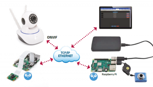
Fig. 1
In this episode, we see how to expand our architecture with a Camera Pi connected to a second Raspberry Pi, all controlled by our Raspberry Pi “concentrator”.
As a “remote” Raspberry Pi you can use any version of Raspberry Pi. If you want to establish a wired network connection, we recommend a Raspberry Pi 2 or 3/3 +. Or you can use the new Raspberry Pi A3 + if you prefer a WiFi connection. For privacy and security reasons, we recommend the “wired” version. In terms of video surveillance, security is very important, as it is, we who want to control any intrusions and not vice versa. If you do not have a very solid basis for managing and protecting networks, it is definitely advisable to create wired networks that are not visible from the outside.
To make the micro SDCard for the second Raspberry Pi, there are two possibilities. Either you create it by installing all the necessary software as indicated in the first article, or you can make a copy of the Raspberry Pi “concentrator” microSD Card, using the “SD Card Copier” tool. You can find it in the “Accessories” item of the Raspberry Pi menu. Insert a micro SDCard into a USB SDCard adapter and insert it into one of the USB connectors of the Raspberry Pi. Copy from the original microSD card to the one inserted in the USB adapter. In this case, video, keyboard and mouse should be connected to the Raspberry Pi to operate from the graphic desktop. You can also take advantage of this configuration to set a possible static IP address, in order to definitively solve the addressing problems. For all these operations you can refer to the book “Enter the world of Raspberry Pi 3+”. While you are there, you can also configure the new micro SDCard. In this case, first, turn off the Raspberry Pi correctly with the command:
sudo shutdown -h now
Insert the new micro SD card in the Raspberry Pi slot and configure it as you prefer. Then insert it into the “remote” Raspberry Pi. In our case we wanted to use a Camera Pi inserted in the CSI (Camera Serial Interface) connector. Obviously insert it with the Raspberry Pi turned off. Gently lift the cable clamp of the CSI connector and insert the flat cable from the Pi chamber into the connector. Be careful to point the blue part of the flat cable towards the Raspberry Pi Ethernet connector and make sure that the flat cable is perfectly perpendicular to the connector. Always close the cable clamp gently. Then connect the network connector and give power. Connect in SSH mode from a remote PC. As a first step, enable Camera Pi. From the command line, type:
sudo raspi-config
Select the “Camera” item (Fig. 2) and, on the next page, select “Yes” (Fig.3). You are asked for a reboot, which you confirm.
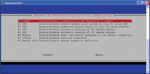
Fig. 2
At this point you can configure the copy of MotionEye on the “peripheral” Raspberry Pi. Open a browser to the Raspberry Pi IP address indicating port 8765:
http://<indirizzo_IP>:8765
log in with the “Admin” user without a password. In the window that opens, if you have created the micro SDCard from scratch, you will have an empty screen, if instead you have copied the micro SD Card of the Raspberry Pi “concentrator” you will have to delete the previously installed video camera. Just select it and click on the trash can icon. Add a password in the “Surveillance Password” field (Fig. 4). It would also be good to do this for the “Admin Password”. Remember, before making the installation definitive above all create your password. The use of assigning a password to the “normal” user and to the “Admin” user is the minimum level of security to protect the system from “indiscreet” eyes. We also recommend that you limit the possibility of access to the video surveillance system, only from within the local network. To allow access from outside the network it is necessary to provide a “chain” of protections that require, at least discretion, knowledge and competence in the design and configuration of network protection schemes, such as firewalls, cryptographic tools, token protections, etc. Never forget that unwanted third-party access to a video surveillance system represents a serious and dangerous violation of privacy and a reversal of the result with respect to the protection you want to create. In practice, from controllers you become controlled. This, at least, is our point of view. After finishing the recording, to add the new camera (Camera Pi), click with the right mouse button on the field at the top right and select “Add Camera”.
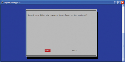
Fig. 3
You are offered a pop-up window where you can choose the features of the camera you want to configure. Different possibilities are available, as each one opens a customized configuration mode, where you can specify the paths and credentials to access the camera itself. In our case, since it is a Camera Pi connected to the CSI connector, you must select the item “Local MMAL Camera”. The “Local” is justified because Camera Pi is connected to the same microcomputer where MotionEye “runs”. MMAL stands for MultiMedia Abstraction Layer which is a C language library created by Broadcom to interface the Raspberry Pi Videocore IV GPU processor, which is the one used by Camera Pi. As confirmation, in the “Camera” field, “VideoCore Camera”, a Pi Camera, is displayed. Confirm and you will be presented with the menu with all the available configuration sections.
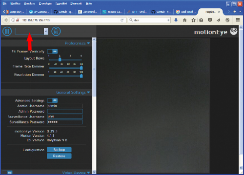
Fig. 4
In the first article of this series, we have described all the configuration possibilities made available in the menu cascade. In our case, with the Raspberry Pi connected remotely, we need the video stream of Camera Pi to be available to the MotionEye application running on the Raspberry Pi “concentrator”. At this point it is possible to configure all the motion control, recording and event management behaviours on the Raspberry Pi where the Camera Pi is installed.
In our case, we preferred to transfer the video streaming of Camera Pi to the Raspberry Pi “concentrator” and manage all the operations from the latter. You can decide where to activate the controls and actions, on the one hand, on the other, or both.

Fig. 5
On the security side, building redundant systems is never a bad idea. The important aspect is to design them, make them and test them correctly. On the remote Raspberry Pi, only configure the settings of the Camera Pi device (Fig. 6) and the output video streaming (Fig. 7).
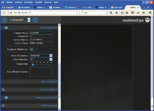
Fig. 6
As for the device configuration, give Camera Pi a recognizable name and then experiment with the other configuration parameters as you wish.
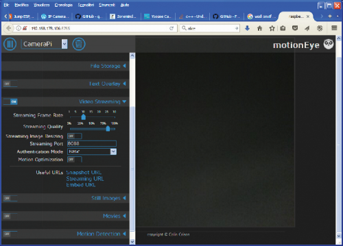
Fig. 7
Activate video streaming. Assign a high-value port, in our case “8088” and set “Authentication Mode” as “Basic”. By clicking on the link “Streaming URL” you get the URL string to be used to connect from the MotionEye “concentrator”. Take note of it.
“Turn off” all other configurations and save with “Apply”.
Log in as “Admin” to the “concentrator” MotionEye application. Click on the window with the name of the cameras and select “Add Camera”. In the initial description window of the camera select “Network Camera”. The fields of the window will expand to request the URL and the connection credentials (Fig. 8). As URL enter what you got from the “Streaming URL” link, usually in the format:
http://<Indirizzo_IP>:<Porta>

Fig. 8
Enter your Username and Password and you should automatically see the recognized camera. You can set the operating modes and response to events, as in the case of a local video camera, which we described in the first article (Fig. 9). As an example, we present the possibility of activating an alarm, using a Raspberry Pi digital pin, in case of detection of a movement by the Camera Pi. Expand the menu item “Motion Notification” and enter the path to two programs in the items “Run A Command” and “Run An End Command” (Fig. 10). The first program visible in List 1 turns on an LED and / or activates a relay connected to a Raspberry Pi pin and the second, visible in List 2, turns off the LED and / or releases the relay. As an example, we used the FT1369 card available from Open electronics, to which it is possible to connect a relay card with digital input and a siren or a light source or any other alarm system.
Listing1
Programma alarm_on.py
#!/usr/bin/python
#import os
import time
import pigpio
pi = pigpio.pi(‘localhost’)
pi.set_mode(24, pigpio.OUTPUT)
pi.write(24, 1)
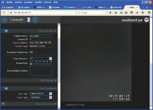
Fig. 9
Remember to enable the “pigpiod” server.
To do this when starting Raspberry Pi, enter a command in the Cron scheduler:
@reboot sudo pigpiod

Fig. 10
if you want to view the recordings made during the “intrusions” click on the triangle icon at the top right of the camera image. The list of recordings made will appear (Fig. 11). From here you can download and view the recorded images.

Fig. 11
In the next article, we will see how to connect a commercial IP camera with the possibility of pan/tilt and which supports the ONVIF communication protocol over TCP/IP. For now, we invite you to experience the remarkable customization possibilities offered by the network architecture created with Raspberry Pi and the MotionEye application.
Listing2
Programma alarm_off.py
#!/usr/bin/python
#import os
import time
import pigpio
pi = pigpio.pi(‘localhost’)
pi.set_mode(24, pigpio.OUTPUT)
pi.write(24, 1)
From openstore
Camera module 8 Megapixel for Raspberry Pi
Raspberry Pi NoIR Infrared Camera Board v2.1 (8MP, 1080p)
