Given two batteries, it chooses the one to connect to the load based on the voltage measured at their poles. It can also be used to switch DC power supplies.
The growing demand for portable devices capable of working where there is no power grid or it is not convenient to use it is rapidly pushing demand of batteries for electronic devices to provide maximum energy density, i.e. the best possible ratio of capacity and encumbrance. When we don’t have a suitable storage battery available for our application, we are often tempted to connect two batteries in parallel with the same nominal voltage, but this solution isn’t ideal, because although it might work at the beginning, it doesn’t guarantee a uniform power distribution, nor long battery life, and not even reliability; especially if the batteries in parallel do not have the same capacity. In fact, electrotechnics teaches us that parallel-connecting two ideal generators of different voltage are not feasible because, given the internal zero value resistance, the one with higher voltage would unload an infinite current on the one with lower voltage. Even if the generators are real, the one with higher voltage gives part of its current to the one with lower voltage. Let’s make the concept clearer with Fig. 1, supposing we have a 12.4 V V1 (which internal resistance is Ri1) and a 12.8 Vcc V2; we set the internal resistance for the latter (Ri2) to be the same of Ri1 at 5 Mohm. These generators will feed a load of RL=4ohm which will, therefore, absorb around 3 A.

Fig. 1
However, even without a load (as shown in Fig. 2), we can already notice that V2 will supply V1 with a voltage of:
Ip=(V2-V1)/(Ri1+Ri2)=40A
Therefore a good amount of the energy is wasted on the internal resistors of the generators, which will dissipate a Pp power equal to a:
Pp=Ip^2*(Ri1+Ri2)=16W
while the load will absorb around 36 W, and that means a loss of around 30%.
In case these generators are batteries, the one with higher voltage will recharge the lower voltage one a little bit until voltages are equalized. However, these recharging process takes place under very different conditions than those indicated by the battery manufacturer. In the previous example, although for a very short amount of time (a few seconds or even less) a battery is charged with a current around 20 times higher than what should be supplied under normal working conditions: likewise, the more charged battery, for the same short amount of time, will see a load of 40 A!

Fig. 2
Two conditions that we must avoid at all costs, in order to ensure a long battery life. Besides, both in the case of batteries and in the case of stepwise power supplies, it is not safe to have such high currents flow in a circuit which would normally withstand currents 10÷20 times the work that.
You can then see that the batteries in parallel issue are not trivial. The first thing that comes to mind in order to solve the issue is to use two diodes, as shown in Fig. 3; this way, the battery with higher voltage will power the RL load until it discharges and reaches the level of the lower voltage battery, then the latter will start supplying current. In case of equal voltages, like voltage drops on the two diets, the two batteries will provide current in parallel; everything apparently works smoothly; there are no high currents circulated, not even if the difference between V1 and V2 is sensible and the difference between Ri1 and Ri2 very small.
However, the problem is the voltage drops on the diodes, amounting to 0.6 – 0.7 V for the PN diodes and 0.2 – 0.3 V for the Schottky diodes. To the voltage drop on the junction, we must add the drop on connections for the diodes capable of withstanding high currents, called bulk resistance; therefore, in a diode capable of withstanding 5 – 10 A it is not unusual to see a voltage drop over 1.1 – 1.2 V.
For this reason, the RL load will receive lower voltage then the generators and a power proportional to the voltage would be dissipated in the diodes. Supposing that each generator supplies an equal amount of current, using the values from the previous example we would have, on each diode, a dissipation of around:
Pd=(Vd*I/2)=Vd*I=~2W
If now the load is powered by V1=V2=12V it will receive VL=V-Vd=11V and power on it will be around 30 W. Since losses are around 4 W, the efficiency of the system showed in Fig. 3 would be around 87%. In order to have a low loss commutation, we must look for alternative solutions, e.g. the one described in these pages.
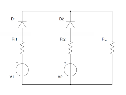
Fig. 3
Circuit diagram
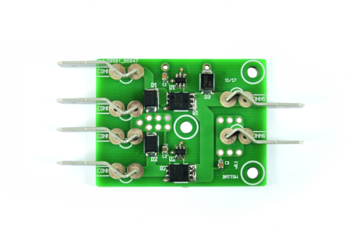
The circuit we are proposing is an automatic battery switch made with power MOSFETs with very low RdsON, which are specifically for SMD but are capable of withstanding noticeable currents since they have very low resistance when adequately polarized. Therefore, these devices are very fitting to act as power switches.
The component employed is a CSD17501Q5A by Texas instruments, capable of withstanding a 30 V Vd and a 100A Ids; the resistance between its drain and source under ON conditions is just 2.4 Mohm.

If we go back to the previous example, the voltage drop for a 3 A load is just 21.6 mV, which is the power dissipation on the most that, for the usual 3 A transit current it is about 65 mW while for a diode, we saw that could be around 4 W. By using to MOSFETs to switch generators on the same load, therefore, the efficiency of this switcher nears 100% (99.82%); besides, the voltage on the load will be basically identical to the generators’. So we have found the ideal actuator, however, in order to carry out our task, which is to create an automatic battery switch, we need a control logic capable of alternately connecting either of the generators with the single load, just like we had tried to do with a couple of diodes. This control system of the MOSFETs can be made with great simplicity thanks to a small IC such as the LM5050, which measures the voltage on the source and drain terminals of the MOSFET and polarizes the gate if the source voltage is over 0.1 V higher than the drain voltage. This way, the battery with the higher voltage will be connected to the load.
Therefore, our circuit can also connect to power supplies in parallel for redundancy (as it is the case on servers and other devices where working operations and power supply must be guaranteed as much as possible). We can also use it to power a utilizer with a battery connected to terminals CONN1 and CONN2 and a power supply on CONN3 and CONN4, this way when the power supply is on, it will be able to supply energy based on the power grid availability, otherwise, the battery will come into action. However, we must take care, because we would need to recharge the batteries separately.
By following this diagram, we can also make a circuit with more than two inputs, by replicating the section composed of C1, D1, U1, Q1 and R1 as many times as the generators we want to “put in parallel”. Obviously, we would have to redesign a printed circuit to host all components in these must be done by following the rules for high currents. The functioning test of the circuit can be easily and comprehensively carried out using a double stabilized power supply, maybe with a display capable of simultaneously read voltage and current for both sections. We are going to put the power supply into “independent” mode, which is with the two separate outputs connected to CONN1 (positive terminal of the first power supply section), CONN2 (negative terminal of the first power supply section), CONN3 (positive terminal of the second power supply section) and CONN4 (negative terminal of the second power supply section) by taking care of following the right polarity of connections if we don’t want to destroy the switcher: given the currents at play, it is not possible (or not efficient anyway) to insert protections for polarity version.
Before turning the power supply on, we would have to calibrate the outputs of both sections of the power supply on zero and connect a small load to the switcher output (connectors CONN5 and CONN6).
Once a power supply is on, we will start by raising the voltage of one section of the power supply and observing the increase of supplied current, while the other section will stay at 0 V of supplied voltage and will not supply nor absorb any current. Now we can increase the voltage of the second section until we go over the voltage value set for the first section. And this is when we will notice the real worth of this circuit: when the voltages will be less than 0.1 V apart, we will notice that the current absorption will slowly “migrate” from the first to the second section, until it will be all on the second section when its voltage will be 0.1 V higher than the first one.
Notice that, in the case of battery, discharge will take place in such a way that, except for a first period when only one battery will be able to provide energy all by itself, within a short time the two batteries will reach the same voltage under load and the current will be supplied to the load by both with essentially a 50/50 partition. And it is also a noticeable advantage because both batteries will be subject to the minimum discharge current possible for a certain load.
The tests run on the circuit using batteries capable of supplying high currents and current related loads (such as a drone motor and its batteries) highlighted an increase in efficiency and battery duration. But above all else, the way of using the energy contained in the two batteries is definitely better than the brutal parallel connection, even when the batteries have had different lifecycles; in fact, if the internal resistance of the battery increased, we could have expected the following scenario: with batteries fully charged, the high voltage drop on the internal resistance of the oldest battery would have had the younger battery powering the load, then – as the latter runs dry – we would have come to a point where voltage suppliable would be higher than the one from the young, partially dead battery.
Now, the oldest battery would power the load by itself, with a higher internal resistance. Therefore, it will be prevalent on the youngest one for a short time, however, during this short time all its energy would be used in the best possible way; and so on and so forth in a cycle of efforts until the actual discharge of both batteries without any – inefficient – energy transmission between the two batteries.
On the other hand, if we connected two batteries of different age directly in parallel, the youngest one would waste part of its energy to recharge – outside of recommended values -the oldest one and the latter wouldn’t have the possibility to efficiently give back that energy.
From openstore

Excellent, I am in the middle of a home Energy Management project that uses (2) 12Ah 12volt batteries with SOLAR to keep it charged. The power is then reduced to 5VDC for the circuits. Currently, the power for the system (BrulTech GEM/DataBox, Universal Devices ISY994I) is supplied by (4) 5VDC transformers. My current control circuit is working on a breadboard using diodes to determine which power source to use. You may wonder why I am using the batteries as my primary source of power… because it is free (after purchasing the needed parts)
Question: can you supply us with the actual parts list.
Thanks
Don
Here is the part list, have a nice time!
Lapo
—–
refdes:value:footprint:digikey:qty
U1:LM5050:sot23-6:LM5050MK-2/NOPBCT-ND:1
D1:MBRS240:do214aa:MBRS240LT3GOSCT-ND:1
CONN1:BATT1+:rs534840:unknown:1
CONN2:BATT1-:rs534840:unknown:1
U2:LM5050:sot23-6:unknown:1
D2:MBRS240:do214aa:unknown:1
CONN3:BATT2+:rs534840:unknown:1
CONN4:BATT2-:rs534840:unknown:1
CONN5:OUT+:rs534840:unknown:1
CONN6:OUT-:rs534840:unknown:1
D3:SMBJ45A:do214aa:SMBJ45AFSCT-ND:1
Q1,Q2:CSD17501Q5A:d8q5a:unknown:2
C1,C2,C3:1u:smd0805:unknown:3
R1,R2:0(LM5050-1)/NM(LM5050-2):smd1206:unknown:2