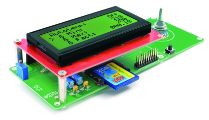
Here’s a simple but essential tool for monitoring the 3Drag and print without the need of a connected computer: all this thanks to a cursor, an SD card slot and an LCD display. Obviously we applied this to our interpretation of the Rep Rap universe (the 3Drag) but you can really easily tweak and adapt to your printer. If you don’t have one, you should consider our super optimized printer. Check it out on the store and in the info page.
One of the main characteristics of 3D printers is their printing slowness: even if of 3Drag mechanic parts are able to exceed the speed of 100 mm per second in printing, an object still requires tens of minutes if not hours to be completed. In fact, as you have a bit more challenging fill or a massive object you easily get to one hour printing time, while those who are accustomed to print multiple parts in one printing batch, organizing them carefully on the printing plate, know that a print like that can take the whole night.
The solution to this problem lies into adding stand-alone printing features: an SD card containing the file to be printed, an LCD panel to display the status, menus and commands, and lastly a system for selection and input. All devices that can be connected to an Arduino board: our printer, like many other RepRaps, sports Arduino at the heart.
Preparation of the software
One of the reasons that led us, a year ago, to prefer Marlin firmware over others (pretty much all equivalent at the time), it was the innovative approach that the creator shown since the very early versions. The choice has proved successful and many other 3D printers now profitably exploit this firmware, also many users now switched from Pronterface to Repetier-Host.
Marlin now allows us to manage stand-alone printing features since it already features all the code needed for this functional mode since few releases.
With or without PC
In implementing the stand-alone printing system, Erik van der Zalm developed a complete and comfortable solution: the user can have an approach like “load, buffer and print” which frees the PC after transferring the file to print to the SD, or even a “print from SD” aproach with absolutely no need for the PC to become part of the process, that is entirely managed via the LCD display added to the printer.

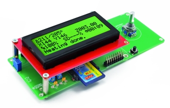
When printing the files from the SD, but with the printer connected to a PC, the firmware communicates via serial with the host computer where you have full control of the printing process thanks to all the options that the best software packages offer. When printing without a PC, instead, we can control the following from the display: the real time temperature, acceleration, velocity, flow rate, preheating, locking and releasing of the engines, the positioning of the plate and extruder plus the commands to start printing manually or automatically via autostart.
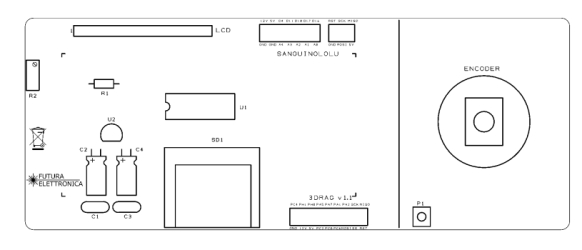
The Schematic
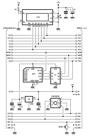
The circuit uses the two Sanguinololu 1.3a board connectors – placed close to the reset button – or the connector of our 3Drag v 1.1 board to bring some data lines to the LCD display, the SPI pins to manage the SD card, three digital inputs for digital encoder, the selection click and the Reset line to allow you to intervene, if necessary.
The Sanguinololu board normally mounts an ATmega 664P with 64K of memory, that’s not sufficient to handle both the SD card and the LCD. Our board instead, already has an ATmega 2560 with 256K flash memory for the firmware, and therefore no problem loading and running Marlin compiled with SD and LCD options enabled.
The display uses only seven connections:
LCD-RS: PB4/PWM (Sanguinololu wrongly indicates D12)
LCD-RW: GND
LCD-E: PC1/SDA
LCD-DB4: A1
LCD-DB5: A2
LCD-DB6: A3
LCD-DB7: A4
The mode of interaction with the Hitachi HD44780 controller is via four data lines: to the two nibbles are sent to recreate a byte. The library needed to use this display type with the necessary protocol is part of the “core” and is therefore present in the basic Arduino IDE distribution.
The SD card instead connects to the ICSP pins featured on the Sanguinololu board for bootloader and firmware programming also with the new microcontroller (without the Arduino bootloader).
SD-CS: A0
SD-DI: MOSI
SD-SCLK: SCK
SD-DO: MISO
As required by the SD and SPI library, other than the ATmega native SPI port pins, a pin is intended for the device select chip and, in our case, A0 has been used, reconfigured as a digital I / O output (PA3 in the case of 3Drag V.1.1 board).
To adapt voltages to the standards levels of SD and microSD cards, both the voltage regulator MCP1702-3302E and the level adapter 74HC4050 are present. The first of the two integrated chips allows us to bring to 3.3 V power to the memory card, thus making the circuit conform to the standards of this type of memory (power may fall as low as 2.7 V, but must not exceed 3.6 V). The component referred to as Encoder, on the diagram, it’s a device that allows us to move the cursor “up” and “down” in the menus: in reality the two switches connected to pins 1, 2, and 3 generate pulses with a rising edge trigger offset to allow you to figure out if the rotation is clockwise or counterclockwise.

The phase shift of the signals on a digital encoder.
Closing the contact between the pins 4 and 5, by pressing on the shaft, the software interprets it as the selection command.
ENCODER-PUSH: PC0/SCL
ENCODER-RIGHT: PD2/RX1
ENCODER-LEFT: PD3/TX1
The reset button is finally connected to the Reset pin of the micro, that is present on the six-pin connector of the ISP that is necessary in the planning stage. For us, it’s important in order to “unlock” the printer in case of crash, error, or other situations in which a reset is is the quickest way to regain control of the situation.
RESET: RESET
All these connections are made on different pins, in the case you use our new control board for 3Drag the 1.1 version. The connections are as follows:
LCD-RS: PA5
LCD-RW: GND
LCD-E: PA7
LCD-DB4: PC0
LCD-DB5: PC2
LCD-DB6: PC4
LCD-DB7: PC6
SD-CS: PA3
SD-DI: MOSI
SD-SCLK: SCK
SD-DO: MISO
ENCODER-PUSH: PA1
ENCODER-RIGHT: PH1
ENCODER-LEFT: PH0
RESET: RESET
The few passive components found on the base are capacitors: these are used to filter the power supply which, although coming from the stabilizer of the printer board, could pick up interferences. The small R2 potentiometer is used to adjust the contrast of the LCD panel, while R1 limits the current drawn by the LED backlight.
The SD card is read through the from SD1 slot; we chose SD and not microSD because we consider it much more physically robust for use with repeated insertions and extractions.
The latest Marlin version already incorporates the 3Drag controller; the changes needed to make Marlin usable with the 3Drag are the following
| Old instruction | New Instruction |
| #define MOTHERBOARD 7 | #define MOTHERBOARD 77 |
| #define TEMP_SENSOR_0 -1 | #define TEMP_SENSOR_0 5 |
| #define DEFAULT_Kp 22.2 | //#define DEFAULT_Kp 22.2 |
| #define DEFAULT_Ki 1.08 | //#define DEFAULT_Ki 1.08 |
| #define DEFAULT_Kd 114 | //#define DEFAULT_Kd 114 |
| // #define DEFAULT_Kp 63.0 | #define DEFAULT_Kp 63.0 |
| // #define DEFAULT_Ki 2.25 | #define DEFAULT_Ki 2.25 |
| // #define DEFAULT_Kd 440 | #define DEFAULT_Kd 440 |
| #define ENDSTOPPULLUP_XMAX | //#define ENDSTOPPULLUP_XMAX |
| #define ENDSTOPPULLUP_YMAX | //#define ENDSTOPPULLUP_YMAX |
| #define ENDSTOPPULLUP_ZMAX | //#define ENDSTOPPULLUP_ZMAX |
| const bool X_ENDSTOPS_INVERTING = true; | const bool X_ENDSTOPS_INVERTING = false; |
| const bool Y_ENDSTOPS_INVERTING = true; | const bool Y_ENDSTOPS_INVERTING = false; |
| const bool Z_ENDSTOPS_INVERTING = true; | const bool Z_ENDSTOPS_INVERTING = false; |
| #define DISABLE_Z false | #define DISABLE_Z true |
| #define INVERT_X_DIR true | #define INVERT_X_DIR false |
| #define INVERT_Z_DIR true | #define INVERT_Z_DIR false |
| #define INVERT_E0_DIR false | #define INVERT_E0_DIR true |
| #define X_MAX_POS 205 | #define X_MAX_POS 200 |
| #define Y_MAX_POS 205 | #define Y_MAX_POS 200 |
| #define Z_MAX_POS 200 | #define Z_MAX_POS 220 |
| #define DEFAULT_AXIS_STEPS_PER_UNIT {78.7402,78.7402,200.0*8/3,760*1.1} | #define DEFAULT_AXIS_STEPS_PER_UNIT {64.25,64.25,2560,600} |
| //#define EEPROM_SETTINGS | #define EEPROM_SETTINGS |
| //#define EEPROM_CHITCHAT | #define EEPROM_CHITCHAT |
To enable the SD card and the LCD change the line
//#define ULTIMAKERCONTROLLER
to
#define ULTIMAKERCONTROLLER
To enable the Hot Bed change the line
#define TEMP_SENSOR_BED 0
to
#define TEMP_SENSOR_BED 5
BOM
R1: 33 ohm
R2: Trimmer 10 kohm
C1: 100 nF
C2: 100 µF 16 VL
C3: 100 nF
C4: 100 µF 16 VL
P1: Microswitch
SD1: SD-Card
U1: 74HC4050
U2: MCP1702-3302E/TO
ENCODER: Encoder
LCD: Display LCD 20×4
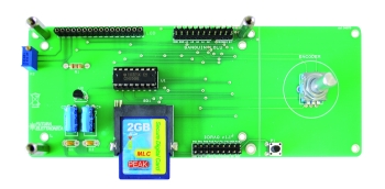
Assembly
The printed circuit board that we provided is of double-sided type and sports traditional components.
The board we created is compatible with the electronics of our first 3Drags (and with all printers using the “Sanguinololu” controller card up to the 1.3a release) through a dedicated connector. Those using a 3Drag with the new board – we designed – should use the connector shown with 3Drag V 1.1. In theory you could then solder only the pinstrip connector that you want to use, without caring about the other.
Preparation of the Software
This control panel for autonomous printing does not contain the features that serve the purpose: the memory contains the files but must be read and the display shows what is sent to it. The actual functionality is contained in the board firmware and specifically in Marlin.
With libraries and add-on code, however, you exceed the 64K memory limit available on ATmega 664P that’s why this is not suitable to operate also the SD and LCD.
All this is well documented by the author of the firmware and in fact, the problem is easily solved by choosing a higher, pin to pin compatible, ATmega version,. The 1284P is best suited for the replacement, while our 3Drag v 1.1 board already sports an ATmega 2560 that has even 256 KB of memory available for the firmware.
As you know, RepRap project was born sporting an Arduino MEGA and then evolved to dedicated board which, however, retain compatibility with Arduino and its IDE. Thanks to this you can reprogram them with great ease as long as the micro already has the bootloader on board.
What changes?
With the activation of the SD part of the firmware, Marlin adds commands and functions to its already impressive arsenal of features. These new features are designed to help you manage files, even from your computer, without having to remove the board to add or edit files that will then be printed. With the onboard memory, the firmware can now queue jobs, always communicating with the printer software through specific messages.
Repetier-Host – the program that we use and recommend – has a specific control panel, located under “Printer -> SD Card Manager”. With this panel you can interact with the printer that, with an SD card inserted, now has the local memory required to “buffer” one or more jobs. It is thanks to this option to download the file, start printing, and then disconnect the computer, that Repetier-Host offers the possibility to add G-code commands at the beginning and end of the file to be printed. Thanks to this feature it becomes easier to put the various heaters off, to position the cart in a given point and then deactivate the engine, reducing the absorption at the end of each printing. This is just an example, based on our practical experience, but the series of commands available with the Marlin firmware can surely inspire other uses.
If an SD card is plugged, the panel shows all the files that you can print. The file system managed by the library allows the use of names in the 8.3 standard with sub directories: in you can go in and out a subdirectory by clicking on the labels shown in the list of files and folders.
Files can be deleted or printed, while, from the panel, you can create a folder or upload a file to be printed later. A PLAY and STOP button are provided to start, pause and stop printing.
The last two icons are used to close the files and allow SD card removal or reading one just inserted.
After having put the fles on the SD, when loading them, remember to be compliant with the 8.3 structure (at most eight characters for the name, a “.” and then up to three characters for the extension – in our case it should be. “g”).
As we will see later, without rebooting the printer (also possible by pressing the Reset button on the panel), you can start the execution of the “auto” file by choosing autostart the from the menu on the LCD.
What to do from the LCD
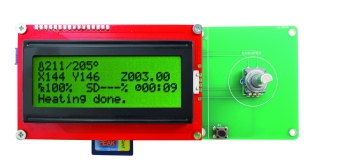
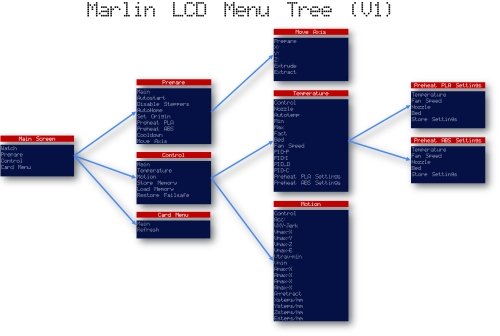
With the display connected and activated, the firmware shows different information, both static, and dynamic. In the image created by the author you can see the whole menu tree, while during printing the unit can be switched to the “Watch” mode showing all functional parameters in Real-time such as the temperature and location of the various axes.
Watch, Prepare, Control, Card Menu: these are the functionalities from which you can manage the printer by controlling what he’s doing (watch), by setting the various functional parameters, activating the heaters, manage movements and parameters permanent (two additional menus levels are provided for this) or access the memory card to choose the file to print.
You can switch between menus by the click of the encoder (when the knob is pressed), then you get back to the previous level if you move to the top of the list of items where there is always the title of the previous menu. To set a parameter, move on it by rotating the encoder, then you click on it, you rotate the knob to change the value, and then you click again to exit to the list. Note that the value changes are applied in real time.
You can also pause printing and access the navigation commands – useful to change the printing thread color.
Open Software & Hardware!
Both the software and the electronics explained here have been developed by various authors who participated in the RepRap community with their work. So we want to express our appreciation for the quality achieved – even greater today thanks to some commercial add ons. This shows how re-circulate changes and improvements, discussing with the community with no secrets or patents brings you a real growth of the material available.
If you have not read the interview with the author of Slic3r, now is precisely the time to do it to better understand what we mean
As we pointed out, we are using the latest versions, but it is very likely that these will soon be superseded by subsequent releases. It is reasonable to assume that the hardware will not be changed, while the firmware and software will almost certainly gain new and different features that we could not documented. Then check the websites of the authors and read the release notes to determine if you should update or keep what you have learned to use.

awesome technology
Nothing new, Ultimaker already sells such units since a year
Yes, this one:
https://shop.ultimaker.com/en/parts-and-upgrades/ulticontroller-ultipanel.html
This version is for 3Drag printer
and Sanguinololu board
http://store.open-electronics.org/3D/3D_electronics/Autonomous_Printing_3Drag
[…] few posts ago we indeed presented a system that complements the 3Drag controller and allows it to print G-Code […]
[…] Here’s a simple but essential tool for monitoring the 3Drag and print without the need of a connected computer: all this thanks to a cursor, an SD card slot and an LCD display. […]
WIll it work with Velleman K8200 ? (clone of 3Drag)
Yes of course ;-)
[…] Another great pillar of 2013, were for sure the 3Drag updates. This year our 3Drag printer grew incredibly in numbers also thanks to the partnership we created with the british manufacturer Velleman, that basically adopted the product and branded K8200 helping us achieve the economies of scale making the 3Drag today one of the cheapest, fully open source, stable 3DPrinters around. This year we shared with an important update of the printer, with an advanced board we created, enabling a few other functionalities including autonomous printing. […]
[…] an interesting number of updates: first we upgraded the Sanguinololu control board, then we added autonomous printing features and lastly, very lately, we added the mod to transform the 3Drag in a CNC Miling […]
[…] The Marlin menu (simplified, by open-electronics.org, CC-BY-SA, image source) […]