
With Arduino Mega, we create, a keyboard with RFID module, a configurable access control system, to manage electric locks.
In the market there are different types of controls for electric locks: from the simple insertion of codes to biometric readers, passing through transponder readers (RFID) or magnetic strips.
The project that we present in this article allows you to control an electric lock via a relay or, more generally, any electrical load that is passed by the relay, by checking six-digit codes and reading RFID transponders.
The man-machine interface of our access control is composed, for the output part, of a 16×2 backlight LCD display and a buzzer, while for the input part we find a 16-key membrane keyboard and an RFID reader.
The administrator user of the system will have a master key that allows access to the system settings, which specifically concern the possibility to insert or remove up to ten numeric codes enabled for access, to associate or disassociate up to ten RFID transponders, to set the time range in which the system will be active and access will be allowed, the number of incorrect attempts after which the system will go into security lockout and the seconds of lockout of the system resulting from such an eventuality.
A further configuration element allows us to set for how many seconds the relay (which, as proposed in the wiring diagram, is located onboard the shield) will remain active upon the insertion of a correct code or upon the passage of an enabled RFID transponder: this feature makes possible not only the control of an electric lock but also the control of a generic electric load that we want to make available only to those who have the credentials to activate it (for example a time-based lighting system, an actuator or an electric pump).
Hardware
To make the project we need the following components, all available from Open Electronics (also online at www.open-electronics.org):
- Arduino Mega 2560;
- Lock shield;
- Membrane keyboard with 16 keys;
- 16×2 LCD display with I²C interface;
- NFC/RFID reader with two transponders;
- Assorted jumpers;
- Power supply 12 Vdc 1 A;
- USB A – USB B cable;
- (optional) Micro SD Storage Board.
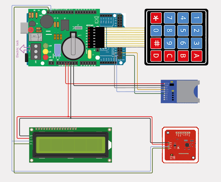
So to create the system we will simply have to get the boards indicated above, which can be purchased already assembled and tested, interconnect them according to the diagram on the next page, find them a suitable container and program the Arduino board with the sketch that we will describe shortly.
Common male/female jumpers are enough to connect the boards together.
We chose to use an Arduino Mega 2560 board as the computing centre of our access control because, with a Flash memory of 256 kB and an SRAM of 8 kB, it allows us to host the ArduLock RFID sketch (which is quite large) and guarantees the possibility to implement this project in the future thanks to its 54 pins.
The lock shield integrates an RTC DS1307 that we will use to read and set the date and time; this RTC has also a control circuit that can verify the lack or insufficiency of the main power supply (Vcc) and make sure that the voltage needed for its operation is taken from the backup battery, in our case a CR2032 3 Volt button cell, which guarantees an autonomy of about 6 months in the absence of power supply.
Always on the shield, we have a buzzer that will be used to communicate with the user through acoustic signals and a relay that will control the electric lock; next to the relay, we find the LED signalling coil excitation: very useful in the development phase of the project to verify the operation of the relay (in addition to the classic “ticking”) without connecting the electric lock.
We also find the eight-pin connector that will allow us to connect the membrane keyboard with 16 keys, more than enough to ensure high security.
The NFC/RFID module we have chosen is extremely flexible: in fact, it measures only 43x41x4 millimeters and is able to communicate in three modes (I²C, SPI and HSU) by setting the DIP switch on board; not only does it support RFID reading and writing but it is able to communicate NFC with another module of the same type or with an Android smartphone up to a distance of about 6 centimeters.
Now let’s move on to the practical implementation: after soldering all components on the PCB of the lockshield following the instructions included in the kit, we place the shield on Arduino Mega by matching the pins below; now we insert the connector of the membrane keyboard on the eight pins on the shield called “keyboard” keeping the keys facing the USB port of Arduino and insert the buffer battery for the RTC.
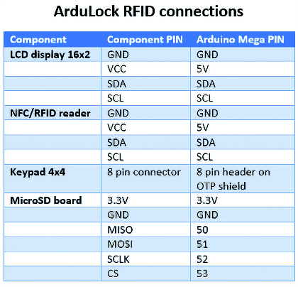
Using jumpers and a breadboard, or with wires and a Stripboard, we derive from the shield pins four lines that we will need later to power and connect the LCD and the RFID module: 5V, GND, SDA and SCL.
Now we move on to the RFID module and set the DIP switch to 1-0 to enable the I²C communication; finally, if we decided to proceed with the jumpers, we solder the four-pin headers on GND, VCC, SDA and SCL, otherwise, we leave the holes free to solder cables.
Firmware
Download the project code and open it with Arduino IDE: as we can see from the first lines we need several libraries.
The EEPROMEx library extends the classic EEPROM management library present by default allowing you to read and write not only bytes but also long, int, float, double, array and even data structures: it is precisely in this way that we will save and recall in memory all the settings of our project, also contains valuable controls to preserve the life of the memory cells that is around 100,000 write operations.
The Keypad library allows us to read the keys pressed on the membrane keyboard while the RTClib library is used to manage the RTC onboard the shield.
The PN532_I2C, PN532 and NfcAdapter libraries manage the RFID module and LiquidCrystal_I2C controls the I²C communication with the LCD display.
After having downloaded and correctly installed all the libraries we can reopen the sketch of our project and proceed to the configuration phase of some fundamental parameters before uploading them to Arduino:
- MASTER_KEY: six-digit administrator code that allows you to enter system settings, we recommend that you choose it carefully and save it without sharing it or writing it down somewhere;
- DEBUG_ON: if uncommented, this define activates the debug serial output (during normal operation we suggest leaving it commented);
- BUZZER_ON: if unmuted, this define activates the buzzer sounds (normally unmuted);
- RESET_TIME: when this value expires in seconds without any input (keystrokes) from the user, if we are in the settings, the system automatically returns to the main menu;
- CONFIRM_KEY: setting of the confirmation key on the membrane keyboard, usually this value must not be changed.
Once finished configuring the sketch, connect the Arduino Mega to the PC via USB cable, select the board and the correct port from the Tools menu and proceed to load the sketch: once loaded we can disconnect the Arduino from the PC.
Before testing our project, let’s analyze the main parts of the code: in the setup function, we find the initialization of the pins, the RTC, the RFID module and the display, finally, we find the initialization of the configuration (settings).
The configuration is a data structure saved on EEPROM containing ten codes and ten RFIDs enabled for access, the start and end times of the input, the number of wrong attempts after which the lock will lock, the seconds the lock will be locked, and the seconds the relay will have to remain active for the electric lock to open.
Below we can see the struct of the configuration:
typedef struct {

long Code[10];

uint32_t RFIDCode[10];

byte HHStartActive;

byte HHEndActive;

byte LockBlockAttempts;

byte LockBlockSeconds;

byte RelayActiveSeconds;

} Configuration;
Each time the system is turned on, the EEPROM cell in position 1 is checked: if this cell contains the value 255 it means that it has not been initialized, then a default configuration is created and written in EEPROM; if instead the cell has a value different from 255 it means that there is a configuration to be loaded in RAM and in this case the configuration structure is populated with the pre-existing data.
The loop function contains two very important functions: ReadKeys and ReadRFID: the first one checks every key that has been pressed and allows, for example, the insertion of an access code or the configuration of some parameters (through ManageActions); the second one checks if a transponder has been approached to the RFID module and, according to the status of the system, it allows to check if the RFID is enabled (by activating the relay) or it allows to associate the RFID. The logic that governs the operation of the sketch is that of the state machine: normally the system is in the state 0 which is the one of code reception or RFID detection (in which the display shows the current date and time), if a code is entered or an RFID is detected and the right conditions are met (correct code or RFID enabled) it goes to a next state such as the activation of the relay or access to the system configuration menu (in the case of insertion of the master key).
How to use Ardulock
Now it’s time to test our project: we power the Arduino via the onboard DC jack with a voltage between 7 and 12 V DC; if everything went well, after a few seconds the display will show the current date and time.
We recommend, at least for the first few times, to activate the debug and use the Arduino serial monitor (speed 115200) keeping the USB cable connected to check for any problems. At the first power up the configuration in EEPROM will be initialized with default values: this means that we will not have any access code and no RFID associated, the lock will be active from 00 to 23 (so all day), the attempts to enter the code will be three, then the lock will lock for ten seconds before allowing new access (either by code or RFID), finally the relay will stay on for one second allowing the electric lock to open.
We insert now the master key that we have invented before loading the sketch and we press the key of confirmation (by default it is #): if we have typed correctly this code on the LCD display will appear the writing “SETTINGS Digit 1-11”, so we type a number from 1 to 11 and we press the # key to confirm: we repeat this operation every time we want to set one of the eleven parameters because at every configuration happened the system will exit from the settings showing us again the initial screen; let’s see in detail the settings:
- 1: allows you to enter an access code (always six digits), confirm with the # key, after validating the code, this will be inserted at the bottom of the list of ten enabled codes, be careful because if the list is full, the code will be inserted in the last available position, scaling all the codes by one position and deleting the code in the first position;
- 2: allows you to locate and remove the access code just entered from the list of enabled codes by entering the position (1-11);
- 3: the system enters in RFID association mode, after having pressed a key from 1 to 10 (without pressing #) we pass an RFID transponder near the module and this will be inserted in the list of the ten enabled RFID, also for this list is valid the same speech of the list of the enabled codes and in the case in which it is all full, that is at the addition of an eleventh RFID, the first RFID in the list will be eliminated;
- 4: allows you to locate and remove an RFID from the list of enabled RFIDs by entering its location (1-11);
- 5: allows you to set the lock activation start time (0-23);
- 6: allows you to set the lock activation end time (0-23);
- 7: allows you to manually set the date of the RTC by inserting it in the format DDMMYYYY;
- 8: allows you to manually set the RTC time by entering it in the HHMMSS format;
- 9: allows you to set the maximum number of wrong attempts before lockout (0-20, 0 means lockout control is off);
- 10: allows you to set the lock seconds if the lock is active (1-120);
- 11: allows you to set the activation seconds of the relay.

After customizing the system by entering some codes and associating the RFID transponders included in the package of the NFC/RFID reader, we can test the activation of the relay: we insert one of the enabled codes and verify that the relay is activated for the preset seconds and that the LCD display shows “CODE OK Lock open”; we also try to insert some wrong codes to test the lock mechanism and the consequent unlocking after a few seconds of waiting (during the lock an X will appear on the display next to the time). Let’s set a lock activation time range that does not include our current time: even if we insert enabled codes or associated RFID, the system will prevent access.
A bit of hacking
We now implement the system by adding a MicroSD module: this will serve to pour all debug messages, which we see in serial, into a text file that we can read from time to time to control all the actions performed by users of ArduLock RFID. Let’s get the MicroSD storage board (available on www.open-electronics.org): this board, 37x23x6mm in size and powered at 3.3 volts DC, has SDIO and SPI connectivity (we’ll use SPI); let’s connect the 3.3V and GND pins to their respective pins on the Arduino, then, since we are working with Arduino Mega, we must connect the MISO pin to Arduino pin 50, the MOSI pin to 51, the SCLK pin to 52 and the CS pin to 53.
Once finished with the connections we get a MicroSD card and insert it into the module ready to receive the log file.
Now open the sketch with Arduino IDE and make changes to implement this feature, as the first thing we include is the SPI and SD libraries, create a define PIN_SD_CS that we set to 53, declare a bool variable SDInitialized that we will need to understand later if we actually have an SD module with MicroSD inserted, then we move to the beginning of the setup function and insert the following lines of code to initialize the module:
pinMode(PIN_SD_CS, OUTPUT);

digitalWrite(PIN_SD_CS, HIGH);

if (!SD.begin(PIN_SD_CS)) {

SDInitialized = false;

WriteLog(“Error: no SD card”);

} else {

SDInitialized = true;

WriteLog(“SD card initialized.”);

}
After entering the initialization of the SD module let’s move to the WriteLog function that we will find at the bottom of the code and insert the following if that allows us to write the log line on a file named “log.txt”:
if(SDInitialized) {

File LogFile = SD.open(“log.txt”, FILE_WRITE);

if(LogFile) {

LogFile.println(LogLine);

LogFile.close();

}

}
We compile and load the code on Arduino, try to carry out some operations, then extract the MicroSD card from the module and read the log.txt file by inserting it into a PC.

We entered the code 112233 (already present in the enabled code list) and the lock opened, then we approached a non-enabled transponder to the RFID reader: in fact, it returned the error “Invalid RFID”; after that, we entered the settings by typing the master key and we selected option 3 that corresponds to the association of a new RFID.
After pressing the 2 keys (without pressing #) we approached the transponder to the reader and the system confirmed the association in position 2 of the list; finally, we tried to approach the transponder again and this time the lock opened because the RFID was recognized as enabled.
Conclusion
At this point, we leave to your imagination possible expansions of the project, but providing some ideas: since we have an RTC, the log file could be created at the beginning of each day with a name like “YYYYY-MM-DD_log. txt” to allow a faster consultation of the logs instead of having to scroll a single log file that records the actions of all days; you could then implement an additional control that scrolls and counts all the free clusters of the SD memory and warns, via the LCD display, that the MicroSD deputed to the recording of the system log is running out of space.
Another implementation is to move the storage of the configuration structure from the EEPROM to the files on the MicroSD; in this way, it will be possible to expand the lists of enabled codes and RFIDs by creating a file for each data to be stored or a single JSON file that contains the whole configuration structure (in this regard, a very interesting library is ArduinoJson).
From OPENSTORE
Shield code activator OTP – to mount
Display LCD 16×2 with I²C interface
