- Building a 3D Digital Clock with ArduinoPosted 4 months ago
- Creating a controller for Minecraft with realistic body movements using ArduinoPosted 5 months ago
- Snowflake with ArduinoPosted 5 months ago
- Holographic Christmas TreePosted 6 months ago
- Segstick: Build Your Own Self-Balancing Vehicle in Just 2 Days with ArduinoPosted 6 months ago
- ZSWatch: An Open-Source Smartwatch Project Based on the Zephyr Operating SystemPosted 7 months ago
- What is IoT and which devices to usePosted 7 months ago
- Maker Faire Rome Unveils Thrilling “Padel Smash Future” Pavilion for Sports EnthusiastsPosted 8 months ago
- Make your curtains smartPosted 8 months ago
- Configuring an ESP8266 for Battery PowerPosted 8 months ago
ANTENNINO a gateway for IoT First episode.

A new application of the Antennino board that realizes a gateway using open-source software, which allows us to realize a control panel (Dashboard) for our wireless devices.
We have introduced you, in issue no. 225, to our Arduino IoT version with a wireless connection, not surprisingly named Antennino; this board can operate, depending on the hardware and firmware configuration, from peripheral or multiple peripherals gateways. Let’s remember, before getting to the very core of this article, that Antennino is a board based on Arduino Uno architecture, natively equipped with a series of connections that can be used for interfacing to local sensors and a UHF radio link to communicate with the outside world. One of its salient features is that, depending on the firmware that you load there, it can work either as a remote unit or peripheral node (edge-point) that interfaces directly to the sensors, or as a concentrator, which would be the node responsible for collecting messages sent by multiple Antennino units operating as a peripheral node. The concentrator is equipped with a small OLED display that acts as a user interface.
In the last project developed with Antennino (issue 228), we explained how to build a gateway having the board configured as a concentrator, but it was a project with a purely educational scope, aimed at highlighting how a network of Antennino-based sensors works. The collected data was displayed directly on the small OLED display and could not be fed into a network or the Internet unless the concentrator was interfaced with a network unit that made it a gateway.
Now, instead, we’re going to implement a real Gateway, where the data of the peripheral Antenninos are not collected merely and displayed, but also interfaced to the web.
To implement this application, we could not use the same hardware as Antennino, but we design from scratch and build a new board, where for connectivity we use an ESP32 module and then the WiFi link, which will act as a bridge to the world of the Internet.
The project
This new Gateway is different from the previous one and more complex; moreover, it is nearly entirely made with commercial modules to be plugged into a motherboard.
We will use the ESP32 module as a classic Arduino, and we will have it communicate with the RFM69 module. As you know, the ESP32 natively supports TCP/IP (WiFi) connectivity, and this opens the door to our sensor ecosystem’s communication with the Internet, so we can talk about IoT.
After a careful evaluation of the possible alternatives, concerning the choice of the Dashboard software, the attention was focused on open-source software (Apache License) that is released in two versions: a Community Edition version and a Professional version. You can download it from https://thingsboard.io.
The Community Edition version can be installed on Raspberry Pi, on a Windows PC, on a Linux server (Ubuntu – CentOS), on Google Cloud, through Doker (Windows or Linux or MacOs) on AWS platform and icing on the cake … it is also available as a fully functional live tool through which you can devote yourself to the first experiments without committing to any installation and without having to pay a single dollar.

For the ablest ones, there is the Professional version that can be instantiated as PaaS services (Platform as a Service, or something that provides developers with a platform and an environment to build applications and Internet services) on Cloud Microsoft Azure or Amazon AWS. Besides, you can activate custom plans to take advantage of the support of the development team.
There is also an additional Open Source Gateway software that allows you to interface with devices that support the protocols OPC-UA, Sigfox, Modbus. Being Open, you can modify the software according to your needs and extend the interfacing possibilities. The code is developed in Java and is available on Github as the Community version of ThingsBoard. We will not use this software, but we will interface our Antennas via MQTT protocol directly to ThingsBoard using our Gateway.
The Thingsboard platform communicates natively via the MQTT protocol.
MQTT: let’s get to know it better
It all began in 1999 with the efforts of two engineers, Andy Stanford-Clark (IBM) and Arlen Nipper (Arcom, now Cirrus Link), who focused on finding a solution to monitor wells and remote assets of Texans oil companies. They came up with the acronym MQTT (Message Queuing Telemetry Transport), and in the same year, they released the first version.
Three years after publication, it was announced that the MQTT would be standardized by OASIS and in October 2014 the MQTT finally received the seal of standardization and version 3.1.1 is now available.
MQTT immediately established itself in the IoT field.
The protocol is now open, available under a royalty-free license after IBM donated it to the Eclipse Paho project in 2011.
The MQTT protocol is suitable for the communication of the embedded devices, with minimum use of energy resources and limited computational capacity; it is particularly suitable for these constraints and in cases where the network allows limited bandwidth.
MQTT travels over TCP/IP network protocol and has low transport overhead, also given a message format with header fixed to 2 bytes, which is also the minimum size of a packet.
MQTT provides three types of Quality of Service. The three levels of service are:
- 0. At most once: Messages are delivered on the best network effort basis, so information may be lost or replicated;
- 1. At least once: ensures that the message arrives, but replicas may occur;
- 2. Exactly once: ensures that messages arrive precisely once.
The developers of Thingsboard have on a particular extent integrated a Broker MQTT in their platform, and then the Gateway that we are going to realize in this episode communicates with the specific Broker MQTT of Thingsboard which supports only the two levels QoS 0 and 1.
How MQTT works
The central role of the architecture is the Broker (intermediary) MQTT (Fig. 1), which is responsible for routing all messages between senders and legitimate recipients.
Each client who posts a message on the broker includes a topic in the body of the message. The topic is routing information for the broker. Each customer who wishes to receive messages subscribes to a specific topic, and the Broker delivers all messages with the corresponding topic to the various clients who subscribed to it.
Therefore, customers do not need to know each other: they only communicate on the topic they wish to subscribe to updates.
This architecture allows highly scalable solutions without dependencies between data producers and data consumers, so you can have completely heterogeneous architectures.
The difference with HTTP is that a client does not have to poll to receive the information it needs, but it is the Broker who notifies the updates on the topics that the client has subscribed, in case there is something new. Therefore, each MQTT client has a permanently open TCP connection to the Broker. If this connection is interrupted for any reason, the broker MQTT can buffer all the messages and send them to the client when it returns online. A client can be at the same time a publisher and a subscriber, on different topics.

Fig. 1
The Gateway
As far as the Gateway is concerned, we decided to create a base with a minimum of pre-welded components on board, to favor modularity. Forms are readily available at www.futurashop.it.
In the first project draft, we were oriented towards the ESP8266 module, but continuing with the implementation, we realized that it would be better to move to the older brother: the ESP32.
Table 1 briefly summarises the differences between the two modules.
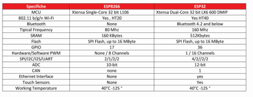
What immediately catches the eye is the greater availability of RAM (almost tripled), the doubled clock frequency, the greater number of GPIOs, but the most important thing is the presence of two Cores.
One core is responsible for the TCP-IP stack management, and the other is dedicated to our Sketch management; this allows for more excellent code stability. While in the case of the ESP8266 chip, the same core must handle both the TCP-IP connection and the user sketch and it is not uncommon for stalled situations to occur that lead to code blocking or malfunctions.
Using ESP32 in the Arduino IDE
To use the ESP32 modules, you need to install what is called the Toolchain: a set of tools and libraries.
To make it easier for the user, we have developed a script that allows you to download everything you need from the Arduino IDE interface.
Let’s make sure we have the latest version of the Arduino IDE, then let’s first add support to the ESP32 module. To do this, we must open the Arduino IDE select from the menu item File/Preferences and open the tab visible in Fig. 2.

Fig. 2
Then enter the following URL in the box “Additional Boards Manager URL” and click on “OK.”
So, let’s restart Arduino’s IDE, and if everything went smoothly, we should find a series of additional boards using the ESP32 module. From the menu, select the desired tab, as shown in Fig. 3.
You will also need to load the libraries used in the project. To help you in the task we have inserted in the lib folder of the GitHub repository, a .zip file containing all the libraries related to the Gateway: insert only those that you do not already have in your folder of the Arduino libraries, because some may already be present because you have already compiled a sketch related to the Antennino modules.
We then restart the Arduino IDE, so that we are ready to open the Gateway sketch, compile it and upload it to the Gateway.

Fig. 3
Memory for the sketch
The ESP32 chip is equipped with external flash memory, as shown in the figure (Fig. 3). This Flash chip is used to store software, data, configuration parameters, etc…
This external memory is connected to the chip via SPI bus and can have a maximum size of 16Mb.
The official Espressif module (ESP-WROOM-32) is equipped with a 4Mb chip. We usually do not see the ESP32 chips and the Flash module because they are enclosed within a metal shield that in Fig. 4 was removed for demonstration purposes.
The overall memory space of the Flash chip is divided into several parts, each of which has a specific purpose.
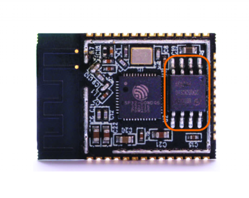
Fig. 4
To see which partition profiles of the Flash Memory normally exist, open the available menu, from the Arduino IDE select, with the commands Tools/Partition Scheme.
In it, we can see that there are four options, each of which corresponds to as many particular uses, and each provides a specific amount of Flash Memory for our sketch (Fig. 5).

Fig. 5
Let’s try selecting the “default” option. Compiling the sketch, we will see (Fig. 6) that a maximum of 1310720 Bytes will be available. While in Fig. 7, selecting the option “No OTA (large APP) we will have at our disposal 2097152 Byte. We, therefore, choose this option for our project.
![]()
Fig. 6
Other options are the communication speed of the serial port, the maximum frequency of the SPI bus of the Flash chip, the mode of operation of the Flash chip and the debug mode.
![]()
Fig. 7
How to load the sketch
To avoid problems, before you start loading the sketch from the IDE interface of
Arduino it is necessary to hold the button “BOOT” that is found to the right of the micro USB connector, we will be able then to release it when it begins to appear the message of log present in Fig. 8. If everything proceeds correctly at the end, the module will reset, and we can test its operation by opening the serial port window to verify the LOG messages. Some important messages are also shown on the OLED display.

Fig. 8
GPRS Module
The Gateway could also be used in an installation where Wi-Fi connectivity is not present, and to overcome this, we have planned to provide connectivity via a small GSM-GPRS module.
The module we are going to use mounts the SIM800 chip that works in the frequency band 1.800 MHz, 1.900 MHz, 850 MHz, 900 MHz and has a maximum data transfer rate of 85,6 kbps.
The use of the MQTT protocol does not require large bandwidths, and therefore, a GPRS connection is more than sufficient. Also, currently on the market have appeared numerous companies that provide specific SIM for the IOT world, and the prices are very attractive.
For the moment we have foreseen it on board of the card, then in the next issues, we will deal with a specific article for its use in the Gateway. The GPRS module needs a power supply voltage that must be in the range 3.4÷4.4V DC with a maximum current of 2A (in the transmission phase), so we need to add a switching power supply module and we will also need to provide an adapter of logical levels for serial communication between the ESP32 and the GPRS module due to the discrepancy in power supply voltage and the fact that the ESP32 module is not 5V-tolerant. We have implemented the logic level translator with the pair of Mosfet N-Channel Q1, Q2 and the four resistors R1, R2, R3, R4.
Electrical Diagram
Let’s take a look at the electrical scheme of the Gateway, which is that of the board that houses all the modules. The configuration is straightforward. Communication between the ESP32 module and RFM69 is initiated via the SPI protocol using the pins provided for this protocol on the ESP32 module.

Fig. 9
In Fig. 9 we see the pin-out of the ESP32 module, and in Table 2, we report a summary of the pins used for SPI communication.
Table 2

Communication between the ESP32 module and the RTC module takes place via the I²C protocol. In Table 3, we have a summary of the pins used, also in this case we have used pins configured in a predefined way to perform this function, namely those of the RTC.
Table 3

The need to use an RTC module is due to the Gateway’s need to send telemetry packets to the Thingsboard that contain a correct Timestamp. This is not necessary for sensors that communicate directly in MQTT with ThingsBoard. On the site, you will find several tutorials explaining how to implement them.
There is also a small OLED display that is controlled by the I²C protocol and therefore shares the Bus with the RTC DS3231 chip. Particular attention should be paid to the pin-out of the OLED module because some models on the market have the power supply pins reversed.
The 3.3V power supply for the RFM69 module and the RTC module is obtained from the controller on board the ESP32 module, which for testing purposes can be powered by the USB cable used to charge the Arduino sketch, while for use in production and especially when using the GPRS module, it will need to be powered by an external power supply connected to the CONN1 connector (Table 4).
Table 4

To connect the antenna of the RFM69 module, we have provided a U.FL connector on the baseboard, that is a pad to which you can weld a piece of wire. As for the ESP32 module, the WiFi antenna is integrated. A CONN2 service connector has been provided to allow access to the GPIO pins that are still free and which could, therefore, be useful for implementing additional functions of the Gateway.
Powering up the SIM800 module
When the gateway is used without the GPRS module, the power supply can also be provided via a good power supply from
5V with micro-USB cable that supplies at least 1A, to be connected directly to the ESP32 module. The on-board AMS117 linear regulator will convert the voltage to the 3.3V necessary for the operation of the Gateway.
When the GPRS module is used, we will have to use an external power supply of greater power to be connected to the CONN1 connector. In this case, it is imperative to use a good quality, stabilized power supply that delivers a maximum output voltage of 12V and a current of at least 2A. This is because the voltage is applied to the Vin pin of the ESP32 module, which has onboard an AMS117 regulator that can withstand a maximum voltage of 15 V, and because the SIM800 module requires a maximum current peak of 2A during data transmission or cell coupling.
Also, particular attention must be paid to the voltage regulation of the Switching module U2: the SIM800 module requires a maximum voltage of 4.4V.
Leave only the U2 regulator on the board, bridge the Jumper JP1, open the Jumper JP2, connect the external power supply (Max 12V) to the CONN1 connector and adjust the trimmer on board the module until the voltage measured with a digital multimeter on the test pins TP1 (GND) and TP2 is equal to 4.4V.
To make sure that there is no change in the setting, we could also seal the trimmer with a drop of silicone or wax. At this point, we remove the external power supply, close the Jumper JP2, connect the GPRS module, and reconnect the external power supply.
Loading sketches and Gateway configuration
The various Sketches can be downloaded from the Github repository, where you can also download the libraries used for the project.
The Gateway code has been divided into three files, all of which must be in the same folder. There is a configuration file User_config.h and two files containing code RFM69.ino and ThingsBoardGateway.ino
In the configuration file, there are only two parameters that require modification: NETWORKID and ENCRYPTKEY.
NETWORKID is currently set to 1. Usually, this is correct, but if you need to have more than 253 Antennino devices, you will have to change this parameter and divide the network into several networks, each with its dedicated gateway because an Antennino network (RFM69) can support up to 253 devices on the same NETWORKID.
The other parameter, ENCRYPTKEY, must be modified because it is the key used to encrypt the communication between the Antennino modules and the gateway. Warning, this must be 16 characters long and must be the same on all nodes in the network, including the Gateway.
The RTC synchronization feature (DS3231) has also been implemented. To synchronize the RTC chip, a library has been created that uses the API of the web service https://timezonedb.com. This is preferable to the synchronization carried out through an NTP server because the latter requires the opening of UDP ports and the code is difficult to port when using the GPRS module. To use the service, which is free for regular use, you must register and obtain a KEY.
In the configuration, there is a parameter that allows you to specify the refresh rate of the RTC through the TimezonedB server.
Once the test procedure has been completed, the variable DEBUG_MODE must be set to false.
Our Gateway code contains the management of the WiFi connection parameters and the ThingsBoard server connection parameters and the KEY for the use of the TimeZonedB timeserver. Everything is implemented through the customization of the WifiManager module.
The Gateway code consists of the usual Setup procedure that is performed only once during the device Boot phase and a Loop procedure that is repeated cyclically during the Gateway operation. In the Setup procedure, the Serial Port, pins, etc. are initialized as usual.
It also intercepts the pressure of the P1 button that is used to reset the configuration of the Gateway. The RTC is initialized (DS3231) the libraries for connection with TimezonedB, MQTT, RFM69.
Particular attention must be placed to the call client.setCallback(MQTTtoRFM69); with which it is instructed the code on the procedure of CallBack relative to the Protocol MQTT, in practice, when the gateway receives a packet MQTT after the reception of data relative to a subscription to a specific topic, the management of these data is delegated to the procedure MQTTtoRFM69() in which the information contained in the format JSON is extracted, and the consequent actions are taken.
In the Loop procedure, a handy thing during debugging is the management of a character received from the serial port (Listing 1). In this way, it is possible to give a particular command (call up a particular procedure while the Gateway is operating for debugging purposes).
In the Loop() the MQTT client connection is verified, and in case the connection is lost the reconnect(); the method is called; while, cyclically if the connection is active the client.loop(); method is called.
In the loop phase, pressing button P1 is also intercepted. Pressing and holding this button resets the WiFi configuration of the ESP32 chip, and then you can change the connection parameters. In the next article, we will see in detail this configuration.
The RFM69toMQTT function forwards the data received from the Antennino nodes by the Gateway to the Thingsboard MQTT server. It is crucial to keep in mind the PublishRPC_Response procedure that allows the operation of RPC calls (Remote Procedure Call) with which you can send commands from ThingsBoard Dashboards to an Antennino device and receive feedback on the execution of the command. This feature has been used to control an Antennino on-board LED from a Dashboard. We will see later how this feature is implemented on ThingsBoard. On the ThingsBoard website, there are examples of GPIO Pin control on simple devices that do not use the Gateway. We invite you to experiment to deeply understand the functioning of the technique when there is no Gateway, which then will be useful to understand the changes that have been necessary for the implementation when there is an intermediary (Gateway) between the module to be controlled and ThingsBoard.
The publication of telemetric data to ThingsBoard is done through the PublishTelemetryData function. Note the particular format that must have the Json payload to be sent:
“{\”RFM69_1\”:[{\”ts\”:1483228800000,\”values\”:{\”BAT\”:2.51,\”T\”:26.38,\”L\”:876.00}}]}”
RFM69_1 is the device identifier that transmits the data, so it is the node RFM69 No. 1.
1483228800000 is the Timestamp from the RTC. BAT is the identifier of the parameter Battery and 2.51 its value read by analogy reading, T the identifier of the parameter Temperature and 26.38 its value read by the sensor to DS18B20 board
The parameter Brightness and 876.00 is identified by its value read by the LDR sensor on board.
Detailed information on which APIs to use can be found at https://thingsboard.io/docs/reference/gateway-mqtt-api
Antennino Node Code – Actuator
As previously mentioned, we have modified the code to the Antenninos to manage the sending of telemetric data in Json format. Also, to take advantage of the ability to control Antennino Pin (RPC) via the ThingsBoard Dashboard, it is necessary that the Antennino module does not go into LowPower mode. Then we configured the module to be powered continuously and modified the code to handle CPR calls.
In Fig. 10 is the jumper arrangement that allows you to obtain the desired power configuration. In this module, we use the power mode through the two AA batteries on board Antennino disabling the timer TPL5110. Most of the code has remained unchanged compared to the already presented code of the Antennine nodes.

Fig. 10
Noteworthy is the block inside the loop in Listing 2. This code intercepts the commands received by the Gateway as a result of requests originating from the Dashboard and prepares the construction of the response to be redirected to the Gateway which in turn will redirect them to the Thingsboard.
One crucial thing is the value of the Request_Id parameter, which is sent by ThingsBoard to keep track of the identity of a sequence of requests and answers between the device and ThingsBoard. In practice, if ThingsBoard sends a command for which it requests a response, the Request_Id code is inserted and must be returned by the Antennino node in response to ThingsBoard. All this in consequence of the asynchrony between calls and answers.
Antennino Node Code – Lowpower
In this case, i.e., using the lowpower mode, the module can go into the low power mode, and therefore, it will not be possible to send remote commands to it via the Dashboard.
We report it in Fig. 11the jumper arrangement that allows obtaining the configuration for the native Low Power mode of the Antennino module (without TPL5110). The code is very similar to that of the Actuator Node, but RPC commands management as well as the Low Power mode management change. Otherwise, the same telemetry data is sent to ThingsBoard.

Fig. 11
Automatic provisioning
An exciting thing about our Gateway and the Antennino nodes is that once added the Gateway device, to make sure that the various Antennino modules that we will add to our network of sensors/actuators appear between the devices on ThingsBoard, it is not necessary to perform any action: it is sufficient to keep the Gateway powered, power the various Antennine nodes that we want to participate in the network and the nodes will appear “magically” under the heading Devices on ThingsBoard with the wording RFM69_1, RFM69_2 … RFM69_XXX.
Where the number XXX after the prefix RFM69_ indicates the number of the node that must be unique to an Antennino network.
We remind you that the Antennino network supports the maximum 255 (253 considering the data gateway and OTA) nodes possible for each network. So, we will benefit from what is referred to as Automatic Provisioning or Deployment. So as soon as one of the nodes will send a packet of data to the Gateway (because let’s remember that the nodes speak directly with our Gateway) the Gateway will redirect the data with the MQTT protocol to ThingsBoard.
Conclusion
All right, we’re done here for now. In the next article, we will conclude this part by addressing the installation and use of ThingsBoard in the creation of the Dashboard.
We have introduced the realization of the Antennino Gateway that will allow us to connect our network of devices to a Thingsboard Dashboard, we have illustrated the peculiarities of the Gateway, and we have introduced the MQTT protocol and the IoT ThingsBoard Dashboard.
From openstore
ANTENNINO – Arduino-RF multifunction board
ESP-WROOM-32 ESP32 ESP-32S Development Board
Breakout Board with RFM69 (434 MHz)
DC/DC Power Converter 1.5V ÷ 35V / 3A

Related Posts


One Comment
Leave a Reply
-
 Arduino ISP (In System Programming) and stand-alone circuits
We use an Arduino to program other ATmega without...
- Posted 12 years ago
-

-

-
 GSM GPS shield for Arduino
Shield for Arduino designed and based on the module...
- Posted 12 years ago
-
 Small Breakout for SIM900 GSM Module
Some post ago we presented a PCB to mount...
- Posted 13 years ago
-
 Join Maker Faire Rome 2024: Innovation Unleashed at Gazometro Ostiense | Calls Now Open!
All Calls Now Open for Maker Faire Rome 2024...
- Posted 2 weeks ago
-
 Building a 3D Digital Clock with Arduino
Project to create a digital clock consisting...
- Posted 4 months ago
-
 Acoustic amplifier – in DIY Kit
This kit creates a microphone amplifier with an output...
- Posted 5 months ago
-
 Creating a controller for Minecraft with realistic body movements using Arduino
Project of a controller that maps body movements...
- Posted 5 months ago
-

Pingback: ANTENNINO a gateway for the IoT – ThingsBoard | Open Electronics