A solid-state amperometric sensor, capable of measuring up to 5 A providing a voltage that is directly proportional to the current.
There are many practical situations where we need to know the current absorption of a circuit branch, a motor or in general, an electric utilizer. Sure, we could just use a multimeter set on amps measurement, but this is not to point, in fact in this context, when we say know we mean to detect a value and transmit it to a circuit that will in turn carry out specific actions. In this case, we need an amperometric sensor capable of providing an appropriate output.
We know that this can be implemented in various ways, according to the coupling with the circuit where we have to take the measurement, which can basically be magnetic (like an amperometric clamp) or galvanic. In this post, we propose a device of this kind, based on a dedicated chip mounted on a breakout board that is very practical to combine to various circuits, such as one of the many Arduino boards or our Fishino boards.
The amperometric sensor described can measure up to 5 A both in direct or alternate current and provides, on the output, and analog voltage that is directly proportional to the detected value, according to a linear relation, although including a fixed offset.
We will better explain this and more by analyzing the circuit on which we are going to install the sensor.
Circuit diagram
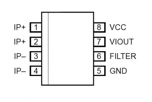
The circuit we propose is based on the ACS712ELCTR-05B-T chip by Allegro Microsystems, which is an integrated current sensor except encapsulated in an 8-pin SOIC container, therefore aimed to SMD, capable of detecting alternate or direct current ranging from 0 to 5 A.
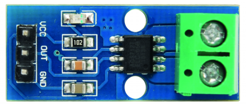
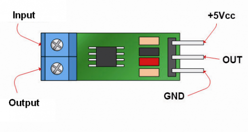
From the diagram, we can notice that the circuit is inserted in the branch where we want to detect current; you can connect it using a bipolar terminal box after interrupting one wire of the line.
Then we have three terminals, two for the power (positive and negative, i.e. Vcc and GND) and one for the output, referenced to ground; the integrated labeled U1 on the circuit diagram provides an output voltage (measurable between OUT and circuit ground) equal to 185 mV for each detected ampere; since the IC can measure current both ways, so both negative and positive values, the range’s purpose is to respect a reference value which is 2.5 V (the exact half of the power voltage required by the IC) if current is zero. By measuring positive values (IMO current on pins 1 and 2, that is IP+) the output will provide 185 mV more for each ampere and by detecting negative currents (positive clarity on pins 3 and 4, that is IP-) OUT will drop by 185 mV for each ampere.
Everything requires 5 Vcc and measurement range is within 0 and 5 A; therefore with positive current, you can find a Vout voltage between OUT and GND equal to:
Vout = 2.5V + 0.185VxI
where I is the current flowing between pins 1,2 and 3,4.
At +5 A, the output will then provide:
Vout = 2.5V + 0,185Vx5 =
= 2.5V + 0,925 = 3,425V
Instead, if detective current is negative, the output voltage will be:
Vout = 2,5V – 0,185VxI
So at -5 A, Vout will be:
Vout = 2.5V – 0.185Vx5 =
= 2,5V – 0,925 = 1,575V
Note how, in case of alternate current detection, voltage provided on output by the integrated circuit will oscillate around to it at 5 V by following the course of the current itself; it is understood that the oscillation will be within the range allowed by the power, which means that it will be positive. In case of sinusoidal alternate current, it will be sinusoidal but unidirectional; if the wave is rectangular, the profile will be the same and polarity will always be positive.

In case of alternate current we can straighten the component provided by the OUT through a classic diode straightener (better if it’s a germanium diode) with capacitive filter at the output, in order to obtain a direct component which is directly proportional to current’s intensity.
List of components
C1: 100 nF ceramic(0805)
C2: 1 nF ceramic(0805)
U1: ACS712ELCTR
LD1: green LED(0805)
R1: 1 KOhm (0805)
Various:
– 2-pole terminal
– 3-way male strip
If we continue analyzing the electric diagram, we can find pin 6, connected to ground through a capacitor acting as bypass and setting the upper limit frequency of the measurement circuit, which, without any bypasses, is equal to 80 kHz; it is better to set limit frequency slightly higher than the current to be measured. Of course, we are talking about measuring variabel or alternate current, because there is no frequency with direct current, i.e. frequency is zero.
Generally speaking, the bypass capacitor (C) is calculated for a filter cut frequency that it forms with the internal Rf which is 20% higher than maximum frequency of the current to be measured, by using the formula:
C = 1/6.28 x Rf x fts
And taking into consideration that Rf is 1.7 kohm. In the formula, fts frequency is expressed in Hz is Rf is in kohm and C in millifarad.
Therefore, in case we want to measure currents at power quit frequency (50 Hz) the capacitor must be selected considering an fts of:
fts = 1.2 x 50 = 60 Hz
And will therefore be:
C = 1/6.28 x 1.7 x 60 = 0.00156mF = 1.56µF
Let’s complete the circuit analysis with the LD1 light diode, powered by Vcc line through the R1 limiting resistor; the diode lights on to indicate when the circuit is functioning (powered).
Before moving on to some use notes, we must mention that there are actually three distinct versions for the ACS712 IC that differ in terms of measurable current, i.e. 5, 20 and 30A, so if you want to detect higher currents you can mount the version you need, provided that if you want to detect 20 and 30 A you must install a fitting terminal box and use a lot of tin for the lines.
In this project, we will use the 5 A version, which can be used for many low-voltage applications, but also for the power grid. In order to stay within the output voltage range compatible with the power, note that 20 and 30 A sensors have lower sensitivity than the 5 A version; to be exact, the 20 A ACS712 has an output voltage excursion of 100 mV/A, while the 30 A one has a drift of 66 mV/A.
Anyway, in order to take the measurement you will have to break one of the current conductors to the load and secure the terminals in the terminal box; we also remind you that if you want to take measurements on high voltage circuits you have to isolate well all the junctions and terminals and make sure to insert the ends of the wires in the terminal box, and pay great care not to touch the circuit with your hands, although only the terminal box pins and pins 1, 2, 3, 4 of ACS712 are subject to high-voltage.
You must also make sure that the circuit is not lying on metallic surfaces and that any possible container is well insulated.
Please note that insertion loss (voltage drop) due to the integrated circuit is negligible, given the very low resistance detectable between the couples of pins 1-2 and 3-4 which is equal to 1,2 mΩ.
Using the sensor
Now, let’s move on to the practical use of the current sensor, which we can directly connect to an end scale 200 µA microamperometer preceded by a voltage divider and 847 kΩ trimmer, and the input of a Arduino board, to let its ADC carry out the measurement and show it on a display, through one of its analog inputs, or allow it to carry out local actions (such as lighting a LED on or cutting off a relay) once said current threshold is reached or when current is cutoff in a utilizer.
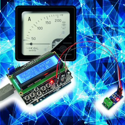
In figure you can see a possible system created by combining our sensor breakout board to an Arduino Uno board equipped with a LCD Shield.
on the other hand, shows the general connection of the breakout board (OUT’s ground is in common with power’s) to the circuit where we have to measure the current and to power and output.
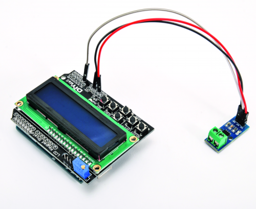
Let’s spend a few paragraphs to talk about the reading made using an Arduino Uno rev. 3 board coupled with a LCD Shield (both can be found on www.futurashop.it) which has been already used in the past and is equipped with a 2-line display for 16 characters and six buttons.
The OUT terminal of the breakout board will be connected to line A1 (analog input A1) of the shield, and it will be brought to the corresponding Arduino Uno rev. through the header (we are not using the A0 because it is already busy, since it is employed by the ATmega328P to read the shield’s keys) while we’re still going to rely on the shield for the power, by connecting Vcc to the 5 V pin of Arduino and the GND 21 of its GND pins.
The sketch you can see in List 1 periodically acquires voltage provided by the OUT from the breakout boards and samples it through ATmega328P’s A/D converter, which works with a predefined 10 bit reference, so each of the 1023 acquirable samples corresponds to 0.0049 V. The function using the sketch is analogRead().
Taking into account the 2.55 V offset (output voltage in standby) and value of each of the ADC units, besides the sensitivity of the ACS712 which is equal to 185 mV/A, value provided by the display will be given by the formula:
I = (0.0049 x unità – 2.5)V / 0.185V
So if the ADC provides a digital value of 600, this means that the current has a value of:
I = (0.0049 x 600 – 2.5)V / 0.185V = = 2.94V-2,5V / 0.185V = 2.38A
This means that if the current goes into pins 1 and 2, while coming out of these, the reading will provide a negative polarity. The sketch works like this: once the line A1 has been assigned, Arduino reads the value between itself and GND and converts it using the above-mentioned formula, therefore sends out the corresponding binary value to the display, which is piloted by the dedicated LiquidCrystal.h library. The ACS712 integrated circuit provides a voltage that instantaneously follows current variation, therefore in order to prevent fluctuations that could alter measurement, we are going read 1000 values in the sketch, and then we calculate the average and send out the result to the display. Since we want one sample per second, we introduce a delay of 1 ms per reading.
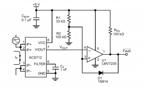
The circuit can also be used without any microcontroller, by connecting its OUT (GND-referenced) to a voltage comparator that is triggered when measured current goes over a set threshold; such an application allows, for instance, by connecting the competitors output to a relay, to disconnect an electric line in case of excessive absorption. The figure shows such circuit, where the comparator is a LMV7235; switching threshold is defined by R1 and R2 and in the figure is 3.76 V, corresponding to 6.8 A (remember that the ACS712 can’t withstand more current than the measurable amount).
The system can also be employed in home applications since nowadays electricity meters are placed far away from the apartment and therefore it is not possible to see the blinking LED indicating the incoming threshold crossing causing the meter to disconnect.
In this application, however, we have to include a shunt (an extremely low-value resistor) between the terminals of the terminal box, allowing for the passage of the current equal to that allowed by the electricity meter, which is around 16 A for a traditional home electricity meter (3.3 kW); you can also replace the provided IC with the 20 A version, labeled ACS712ELCTR-20B-T, and in this case you won’t have to install a shunt.
However, if you are going to use a shunt, this must be calculated by considering the anti-parallel formula, once established that maximum current between pin couples 1-2 and 3-4 of our ACS712 is 5 A and that you should have a voltage drop equal to the product between the shunt’s resistance and the current itself:
V = 1.2mΩ x 5A = 6mV
Now, let’s suppose we want to measure to 16 A of the power grid at around 220 Vca, while keeping that drop, we get that the new resistance must be placed between the terminal box’s terminal, which is:
Rtot = 6mV / 16A = 0.375mΩ
Given that the IC’s internal resistance (Ri) is fixed and known, we know from electrotechnics that the parallel of two resistors can be determined using the formula:
Rtot = Ri x Rs /(Ri+Rs)
We then find the resistance of the shunt (Rs) that we will use to deviate the excess current, which is the current that does not flow through the ACS712 but parallel to it, in the shunt:
Rs = Rtot x Ri / (Ri – Rtot) =
= 0,375mΩ x 1,2mΩ / (0,825mΩ) = = 0,54mΩ
Therefore, we have to place a 0.54 milliohm shunt parallel to the pins of the terminal box; this kind of resistors are available ready-made, e.g. for electronic measurement instruments (we can find them in both analog and digital testers); we have to consider the power of around 0.6 W the maximum current of 11 A (i.e. 16 minus 5 corresponding to the maximum current flowing through ACS712 in order to be measured correctly).

The shunt can be made also by using a segment of naked copper wire, considering the typical resistance of this material which is 16 milliohm per meter, per mm², therefore a 1 mm², 1 cm long wire will have a 0,16 milliohm resistance and in order to obtain our 0,54 mΩ we will need 3,5 cm of it.
Conclusions
Current measurement in a circuit branch or in a wire powering a utilizer can now be carried out with great precision and safety, thanks to the integrated circuits from the ACS712 series: the technique we use, based on the detection of the electromagnetic field produced by a conductor running through the integrated, allows to concentrate the advantages of various measurement techniques in just one component, providing a precise measurement and, thanks to Hall effect, allows to determine the current without the coupling, with minimum insertion loss (voltage drop), linearity and possibility to measure both direct and alternate currents.
All of this would be impossible using conventional techniques, because in order to obtain galvanic isolation, we would have to make use of photocouplers, however, these do not grant linearity and cause insertion losses of a couple volts, or we could use coils, but they would only allow measuring alternate currents and not direct currents. In order to have low insertion losses and measure both direct and alternate current we should carry out the galvanic coupling with a low-value shunt, but this again would present issues and risks without installation.
On the other hand, as we have just shown you, by using the small circuit based on the ACS712 sensor, taking measurements and assessing data with discrete circuits or microcontrollers becomes very easy.
From Openstore
