It is based on the DFRobot module, and enables the playing of musical tracks that have been recorded on a microSD or on a USB Pen Drive; it is supplied with outputs that enable to connect it to the AUX socket, the one most Car Audio Systems are provided with.
Car Hi-Fi systems – both OEM (Original Equipment Manufacturers) and aftermarket ones – have evolved in time, in order to adjust to new music media. While the radio has always been the same (sound always comes from a radio receiver, independently from the fact that it is an analog radio or a DAB/DAB+ one), the player has evolved from the cassette player (at first a stereo 8 one, then a stereo 7 one) to the Compact Disc to eventually feature an MP3 player. This compressed format is an extremely practical one, since a single device stores hours of uninterrupted music (in the MP3 format, a MB corresponds to about a minute of a hi-fi audio file, sampled at 44.1 kHz); for those who go on long journeys, that means that it is possible to listen to your music, without the need to periodically change your Compact Disc, or to buy expensive or bulky CD changers.

Still for the purpose of taking advantage of the MP3 format, Car Hi-Fi system s supplied with a USB socket were born, and they enable the access to a lot more MB (if not GB!) of digital music in a compressed format; moreover they do that on a device that just about anyone has in his pockets: that’s the USB flash drive (also known as pen drive).
With the arrival of the Bluetooth, the multimedia files contained in a smartphone have been made available to the Car Hi-Fi system, by means of the audio connection and of the AUDIO profile of the Bluetooth itself, thus further extending the possible uses.
Unfortunately, not all car radios are supplied with the Bluetooth or the USB technology, but they still have an auxiliary audio input (signed as AUX) that may be accessed via a jack socket.By taking advantage of this, you will be able to connect a MP3 player such as the one shown here; it is based on the DFR0299 module that you already met when we dealt with the Presepino and the MP3 Demoboard projects.
In this circuit, it has been used in a configuration for a simplified manual control, that is to say we are gonna manage it by means of the buttons, as with the demoboard, by drawing the audio signal from its BF stereo low level output.
Our circuit
Before going on with the analysis of the circuit diagram we would like to say a word or two on the subject of the MP3 module, that has been designed for the purpose of playing the MP3 and WAV files that have been stored on a microSD-Card having a maximum capacity of 32 GB (as long as it has been formatted to FAT16 or FAT32) or from a pen drive, still having a maximum capacity of 32 GB (and formatted in the same way as explained for the microSD Card).
The MP3 module has been designed and developed for the Arduino world, and it may operate autonomously. It’s not a case that we use it like that – by means of the buttons – in the project, you will find in these pages. Thanks to them, it is possible to command its functions, that we need in order to listen to the tracks; more specifically, in order to reduce the size of the printed circuit board as much as possible, we added just three buttons (Play, Next, Prev), so that only the basic functions are kept (that is to say, to sequentially skip to the next track or to the previous one found in the archive you are using, and to start the reproduction).
It is therefore not possible to directly access a certain track (that is something that is not anyway supported by the DFR0299 module), but we believe that it is possible to do without such a function; also, there is not much space for distractions, in a car.
The module contains a decoder, capable of decompressing the audio in the MP3 format, and a microcontroller, capable of accessing the data contained in the microSD-Card, via SPI: gradually, the data stream is read, and the decoder converts it into uncompressed audio, that is then amplified by a small integrated final amplifier; the latter is a mono one having a 3 watt bridge output, that’s more than enough power to drive a loudspeaker capable of “being heard” in the environment. The output of the said amplifier refers to the module’s SPK1 and SPK2 pins, however, the DFR0299 module makes the L and R high impedance and low level stereo audio outputs individually accessible; they are fine for the purpose of directly driving the AUX stereo input of the car Hi-Fi on board. You may, therefore, be satisfied with the mono audio output, or choose to draw the audio from the module’s pins 4 (LEFT output) and 5 (RIGHT output) and to bring it to the RCA sockets of the Car Hi-Fi system ’s AUX, by means of a small stereo audio cable (a shielded one) and two RCA plugs. The stereo output has been made accessible from the 3.5 mm jack plug found on the board.
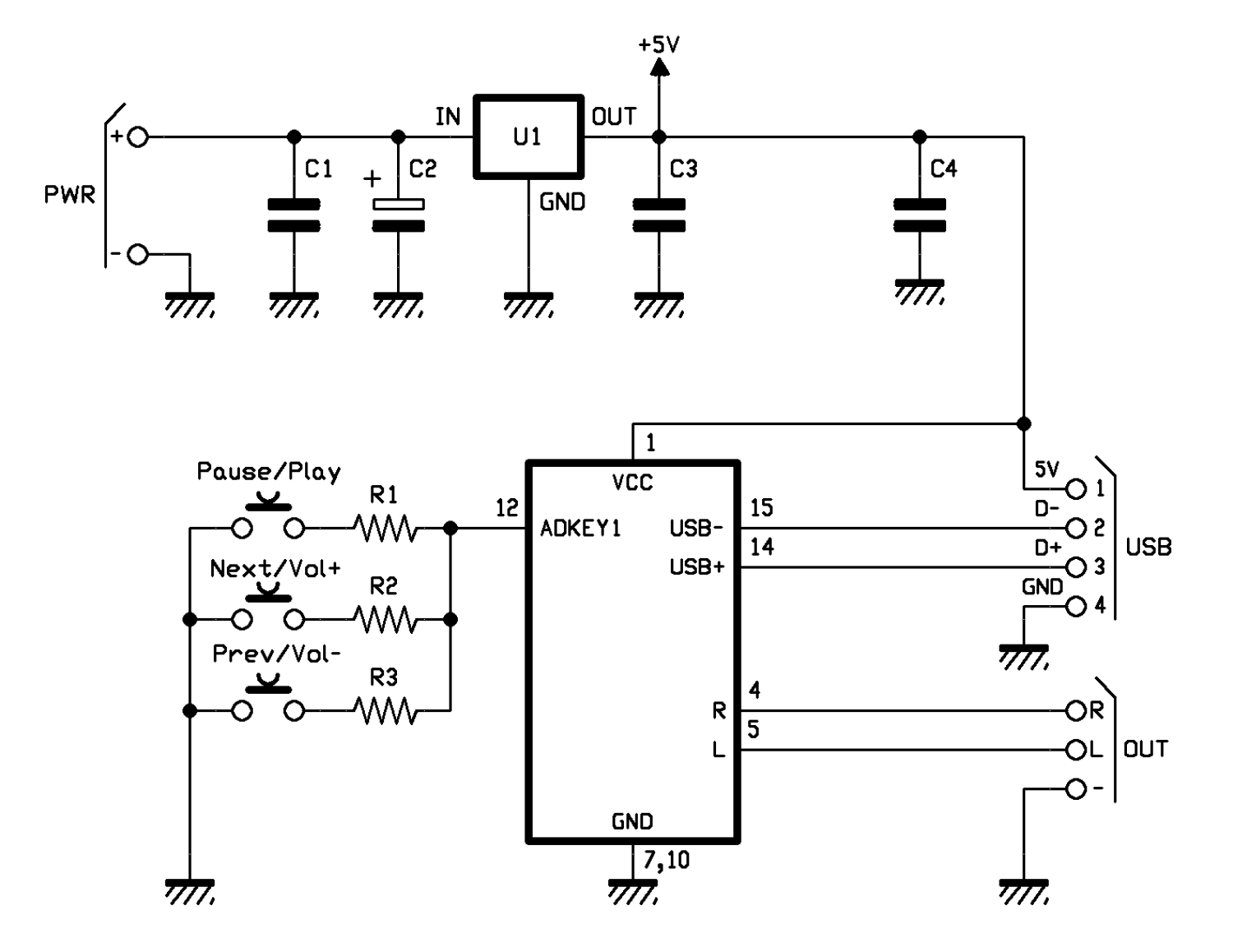
All the module’s functions that we implemented are managed by means of the buttons placed on the printed circuit board, as the circuit diagram shows. And now, after this introduction, we may start to analyze the latter.
Please notice that, in order to read the buttons’ state we used a gimmick that uses the A/D converter that is internal to the microcontroller (that manages the MP3 module) and that has been assigned to the ADKEY1 line; such a solution enables to acquire the state of three buttons by using a single line of the U2. By the way, that’s exactly the one that the manufacturer provided in order to minimize the number of lines – and therefore of pins – for the connection to the external world.
More precisely, we would like to remind that the ADC lines that have been destined to the button management are two (ADKEY1 and ADKEY2), but as for our project, one is more than enough.
The reading of the buttons is carried out by detecting the voltage that the pressure and consequent closing of each of them create at the input they are connected to; such a voltage depends on the resistor in series to the button.

For the sake of completeness, we will say that both ADKEY1 and ADKEY2 are provided with a pull-up resistor that is internal to the module; it will act as a voltage divider with the resistor placed in series to each button, thus determining – when the button is pressed – a certain voltage. In the firmware, a table of values is found: each one of them corresponds to the reading of the ADC for each one of the buttons found (here they are only three, but ADKEY1 supports up to 10 of them, and the same goes for ADKEY2). For example, by closing Pause/Play a potential is created on ADKEY1, and it is different from the one that would be generated when acting on Next/Vol+ or on Prev/Vol-, and so on.
Even though in this project we only use three buttons, it is useful to know that actually ADKEY1 is needed in order to read the 6 function buttons (you may see three of them in the circuit), in addition to the first four ones for the direct access to the tracks, if you opt for such a mode (that has not been used here); on the other hand, ADKEY2 (that has not been used in this project) is used for the purpose of reading the remaining buttons for the direct access to the tracks.
That being said, let’s see the functions of the three buttons found in the circuit: the first one, that is to say Pause/Play, is used in order to pause the ongoing reproduction, or to restart it, if it has been paused. Moreover, it is needed in order to start the playing the first track.
The Next/Vol+ button has a twofold function as well: if pressed briefly it makes us skip – when we are playing a track – to the next one.

If it is pressed for a longer period of time, it increases the volume (that is to say, the level of the audio signal supplied to the outputs and to the module’s integrated amplifier) at a constant rate, and until it is released.
Similarly, when the Prev/Vol- button is briefly pressed, it jumps – from playing the current track – to the previous one (for example, if the player is reproducing the tenth file, it starts playing the ninth one), while when it is pressed for a long enough period of time, it gradually lowers the volume, until it is released.
Still on the subject of the volume, please notice that at the beginning it automatically starts at the highest volume, and therefore you will have to adjust it by means of the buttons (more precisely, you will have to act on the Prev/Vol- button), so to adapt it to your needs.
Well, after the analysis of the buttons (that make up the board’s user interface), we may move on to examining the communication ports. Here, in particular, that’s just the USB one, that refers to the USB-A connector and internally to the USB interface of the Device type; it has been configured by the manufacturer for the purpose of being used as an interface towards the pen drive from which to load the files to be played. Even though our module may be controlled by means of a serial interface at a TTL level, in our circuit we do not use such a function and the only USB you will see in the circuit diagram is the one that has been integrated into the module, and that is used in order to load the MP3 tracks from the USB mass storage device.

Please notice that the module enables (by means of a command given from the U/SD/SPI button that has not been provided here) the possibility to manually select the source from which to read the file to be played (U/TF/SPI/Sleep): when it is pressed, it changes from the USB to the SD-Card, and then from the SD-Card to the SPI; the third time it is pressed, it brings to the Sleep Mode, and then it restarts; however such a function has not been used, since in order to take up only a minimal amount of space we did not provide a button for the selection of the playing source (USB/SD). Therefore, here we take advantage of the automatic selection that is provided by the module.
For example, if we insert the microSD (and not the pen drive), the playing is directly carried out from the microSD; while if we insert the USB pen drive only, at the start the playing is carried out from the pen drive. In the case in which the microSD is found, and we insert the USB pen drive, it will stop playing, and by pressing the Pause/Play button it will automatically move on to playing from the USB pen drive, or vice versa. In practice, each time we insert a second physical device, the playing will stop and will wait until the Play command is given, in order to start playing from the new device that has been inserted.

The whole circuit is powered by a direct voltage with a value between 9 and 12 V, and the U1 regulator draws the 5 volt needed by the MP3 module from the main power source.
The C1 and C2 capacitors filter the input power (+ and – PWR contacts of the circuit), while the 5 stabilized volts from the 7805 regulator are filtered by C3 and C4. The last two capacitors locally filter the 5 volt, thus preventing the noises propagated on the power line to influence the activity of the microcontroller managing the MP3 module.
Tests and usage
Once you have completed assembling it, you may immediately try the MP3 player, by powering it by means of a direct voltage source with a voltage between 9 and 12 volt, and capable of supplying 500 milliampere (if you wish to connect the module’s mono output to a loudspeaker, otherwise it should be 200 milliamperes if you wish to connect headphones or a stereo jack plug to an amplifier’s input).
We would like to remind you that you may connect the Car Hi-Fi system ’s AUX input (in this case you will have to join the left and the right channels) to the jack socket, by means of a specific jack/RCA cable.
You will have to connect the power source, on the other hand, by means of a piece of a flat cable (possibly a red/black one, or with a marked conductor, so to help to recognize the polarities) to a cigarette lighter plug.

Please press the Pause/Play button and check that the first track is played; then please adjust the volume by means of the Prev/Vol-, since it will probably be too loud, given that the module automatically starts from the highest volume (in the beginning, therefore, the volume may only be lowered).
As hinted before, the player supports the MP3 and WAV files and automatically starts reading from a pen drive or microSD if only one of them is inserted; therefore please never insert both at the same time.
In order that the MP3 module may detect and play the audio files contained in the mass storage device, it is enough that they are supplied in the above said formats; it will be the module to deal with what is left to do, and it will first search in the device’s root directory, and then in all the folders found (in the above said order).
By starting the playing via Pause/Play, the circuit will play the tracks in order.
From openstore
Demoboard MP3 audio player DFR0299

3conjuncture