
We melt metals using the ZVS (Zero Voltage Switching) technique, applied to a 1000 W RLC resonant circuit.
Have you ever wondered how powerful the electric-magnetic fields around us can get? The question is fitting because nowadays we have a lot of examples showing how we are surrounded by countless electromagnetic waves, due for example to electric network cables, radio and TV repeaters, mobile cell towers and RC remotes. You just have to take a mobile phone next to the receiver of a landline phone or a speaker to hear some crackling, or take a walk in the dark under a high-voltage line with the neon light and see that neon lighting on. These waves that the naked human eye cannot see are actually very present and invasive in our everyday life, although their effect is relevant only in just a few cases and proportionately to the power irradiated and our distance from the source. How powerful can an electromagnetic field get? The microwave oven found in many households show they can heat up food and create electrical arcs when we put in metal utensils or aluminum foil by mistake. However, can an electromagnetic field get so powerful to get an electric conductor white-hot in a few seconds?

The answer is yes and the project we are presenting today provides clear evidence of that. In fact, it is a system that operates by taking advantage of three physical phenomena that we as electronics technicians should have studied in school: the magnetic induction principle, the Foucault currents principle and the Joule effect. Our project shows how to heat up and eventually fuse conductive materials and especially ferromagnetic materials with electricity using a ZVS circuit with a nominal power of 1000 W that can be pushed to 1500 under specific conditions.
ZVS are the initials of Zero Voltage Switching, a technique used in electronic power converters in order to increase performances, in fact, semiconductors commute with an almost null voltage at their terminals so the V x I product decreases and, as a consequence, commutation losses are extremely low, as we are going to see in-depth later in the paragraph dedicated to the functioning principle.
In the circuit, we are going to apply the same concept that is the base of the functioning of induction stoves, the type of stoves often used abroad where electric power is cheaper.
An induction stove is usually made of a coil in which a high electric current pass through, or a time variable current, which produces a magnetic field that is proportional to the current generated. Due to the Faraday’s law, a variation in the magnetic field over time produces an induced electromotive force in any electric conductive body that is invested by the force lines emanating from the field. This electromotive force originates induced electric currents circulating in the material of the pot or container placed on the stove; these are called parasite currents or Foucault currents or Eddy currents. These currents are caused by the Joule effect, the heat generation caused by energy loss as a consequence. In the case of induction cooking, thermal energy dissipation makes the part heat up, just like it happens in mechanics with friction, which is a resistance force that results in kinetic energy dissipation as heat. However, induction cooking is a particular case, because the effect of the currents induced by the electromagnetic fields is different based on the magnetic permeability of materials immersed in those fields, their magnetic reluctances and electric conductivity. This explains why we cannot put a metal pot in a microwave oven (let alone a steel one) but we can cook meat, while meat can cook on an induction stove if it’s inside a pot with a steel bottom. In fact, in the first case heat is generated inside the food and in the second case, it is generated at the bottom of the pan, because some materials heat up sensibly at low frequencies and some others require microwaves.
Usually, parasite currents are in effect we want to avoid, because it implicates losses, for instance, think about leaks in a transformer’s core. On the other hand, in our case, we want to highlight it in order to generate heat in the body invested by the magnetic field; specifically, we are talking about ferromagnetic materials which can be strongly heated up at working frequencies of the circuit.
Besides heating metals and possibly melting them, the circuit can also be employed in other interesting applications, like energy transmission in the ether through the use of coupled coils synchronized on the resource frequency (wireless power) and trigger circuits for Tesla coils.
CIRCUIT DIAGRAM
When we take a look at the circuit diagram we notice a 2-branched symmetrical structure in the control circuit, called Royer oscillator, which is a circuit that allows self-oscillation of an RLC block at its natural resonance frequency.
The RLC block is composed for the L part of a coil commonly called “work-coil”, for the C part of a so-called
“tank-capacitor”, several capacitors connected in parallel and for the R part it is composed of series-connected resistances introduced by to components and the connections. Once powered on, the oscillator starts resonating and thanks to the elevated extra-resonance current circulating in the work-coil, it is able to generate a strong magnetic field.
When the Royer oscillator is powered on, as symmetrical as the two branches are, one of the two MOSFETs M1 and M2 will start conducting first, because the two MOSFETs will never be exactly the same.
Let’s suppose that the M1 starts conducting first and its drain terminal goes to ground voltage and this forces M2 to turn off, thanks to the feedback diode D1 which starts conducting and quickly takes gates charge from M2.
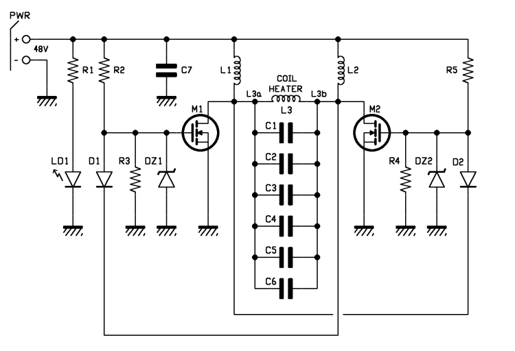
The resonant circuit composed by the L3 inductor and the parallel capacitors C1, C2, C3, C4, C5, C6 shows a sinusoidal semi-wave to M2’s drain terminal that goes from zero to max and then back to zero; when the semi-wave goes back to zero the D2 diode turns on and it forces M1 to turn off and M2 turns on making the circuit generate the other sinusoidal semi wave. From this moment on, the cycle repeats with the specific resonance frequency of the RLC block and, on the L3 coil of the work-coil we will have an elevated sinusoidal current at the frequency of around 100 kHz; this value, which would have food to heat up just a little bit, already generates a remarkable heating inside a bolt, that grows when we have a certain electric power available and the consequent electromagnetic induction. In the oscillator, the MOSFETs work in counter phase, i.e. when M1 is on, M2 is off and vice versa; this is granted by the presence of the resonating circuit and the feedback diode D1 and D2; if the two MOSFETs didn’t conduct simultaneously, there would be no short-circuit current limitation and the MOSFETs would be destroyed due to the excessive current.
Commutation into the MOSFETs takes place with a voltage between the drain and source terminals (Vds) that is almost 0, i.e. under conditions of Zero Voltage Switching (hence the initials ZVS) and therefore dissipated power during commutation is minimized and equal to:
Pd = Vds x Id
Where Id is the drain current. Furthermore, thanks to this ZVS technique, radiofrequency disturbances produced during commutation, which the circuit naturally radiates in the surrounding air, are sensibly reduced.
M1 and M2 MOSFETs are IRFP260N by Infineon, characterized by a really low Rdson (only 40 mΩ) and a high drain current (ID=50A); they are Fast Switching type, which means they switch from full conduction (on) to interdiction really quickly and this is also the case for the integrated protection diodes we placed in anti-parallel, which require a TRR parameter (Reverse Recovery time) of around 400 ns.

Max peak voltage in a ZVS commutation circuit is equal to:
VPEAK = VSUPPY x p
Since we have limited power voltage 248 Vcc, we have selected 200 V as maximum voltage comparator between drain and source (Vdss).
D1 and D2 retroaction diodes are MUR420 and they also must be Fast Switching, in order to readily turn off the MOSFET to which their anode is connected and they must sustain a current of at least 4 A. In order to turn on the GATES of the two MOSFETs there are two power resistance R2 and R5 of 470 Ω.
In order to protect the MOSFETs from extra voltages and extra currents there are two Zener diode–resistance couples R3/DZ1 and R4/DZ2. R3 and R4 have a value of 10 kΩ; DZ1 and DZ2 are 12V – 1W.
LD1 LED signals when there is power and it is powered through the 4,7 kΩ R1 series resistor limiting its current. L1 and L2 inductors have a value of 100 mH and are used to limit voltage spikes during commutation that might destroy the MOSFETs and are coiled on toroidal cores with a maximum current capacity of 13 A.
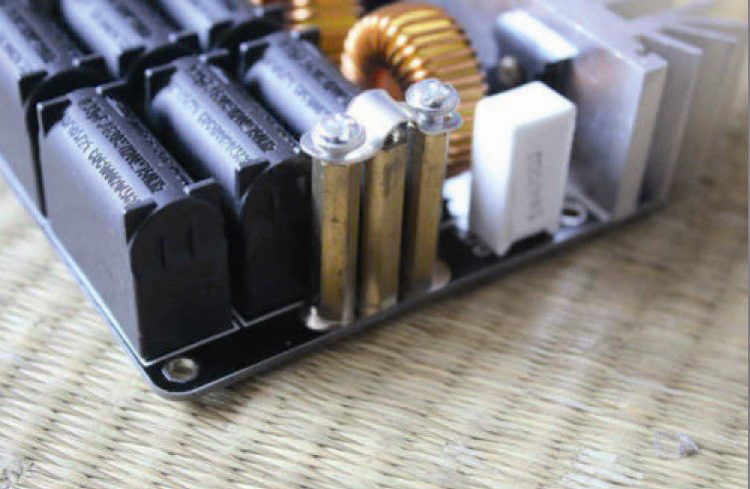
C1, C2, C3, C4, C5, C6 capacitors are made of MKP polypropylene in order to sustain the high current and resonance voltage and limit losses.
In our circuit, we have selected a resonance capacity of around 2 mF composed might parallel of 6 0,33 mF capacitors and a working voltage of 630 V.
The work-coil, that is the coil which we are going to introduce the object to heat/melt in, is made of 6 coils of 0.8 mm thick copper with a diameter of 6 mm which is freely-coiled in order to sustain strong currents, better dissipate generated heat and minimize losses due to the skin effect that, at frequency of 100 kHz, tends to make the current flow in the circular crown of the conductor.

Coils must not touch each other (because the copper is naked), otherwise this would result in a short circuit that would reduce their number and alter the inductance value.
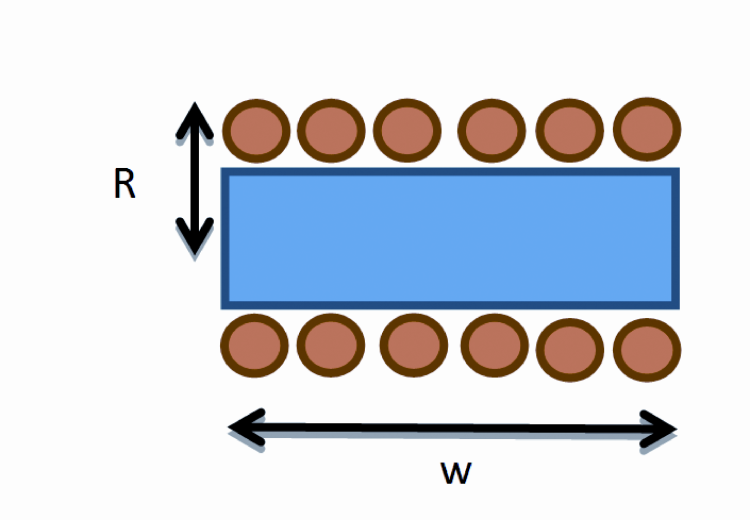
The work-coil has a theoretical inductance of around 1,26 mH, but it may vary according to the length of the horizontal branches that connects it to the capacitors. In order to calculate the theoretical auto-inductance value you can use this formula:
L = m0 N2 p R2/w
where m0 is magnetic permeability in the void (m0 = 4 p 10-7H/ m), N is the number of coils (in our case 6),
R is 2,5 x 10⁻² m e w = 7 x 10⁻² m, therefore L equals to 1,26 mH.
You can use this formula to calculate the value of theoretical resonance frequency:
fR= 1 / (2p * Ö(L C)) = 100,3 kHz
where L =1,26 mH, C = 2mF.
USAGE
The circuit must be powered by a direct voltage ranging from 10 to 48 V with enough power; if you apply the maximum provided voltage of the 48 Vcc, we suggest a power supply with a power not below 1500 W. Insert positive and negative wires coming from the power supply in the terminal making sure that polarity is correct and tighten the screws. Power circuit between the + and – terminals and make sure the green LD1 LED turns on to indicate input voltage.

Now, a resonance current of around 100 kHz should flow within the work-coil. If you use maximum provided voltage (48 Vcc) to power it without introducing metal objects within the work-coil, power absorbance is aware than 500 W; on the other hand, by introducing a conductor, based on its material, dimensions, geometry and position, absorbed power can vary greatly up to a maximum of 1500 W.
Once selected the conductive object to insert in the work-coil, e.g. a metal screw, take it and keep it in position with pliers (which must not get too near to the coils) to avoid burning yourself.
Slowly insert the conductive object inside the work-coil, trying not to touch the walls of the coil. Keep the conductive object in the vertical position inside the work-coil. The conductive object acts as secondary for the transformer that has the work-coil as the primary element and since it is inside a solenoid, the conductive material is invested by the magnetic field lines with more power compared to the outside of the solenoid. In a short time, the inserted material heats up due to Joule effect and its color changes becoming orange–yellow, as it is typical for incandescent objects.

This condition can be maintained for a few tens of seconds, but you have to keep in mind that temperature gets really high therefore you must be really careful not to directly touch the conductor element or the work-coil or the dissipators in order to avoid burns.
Please note that after using the ZVS Induction Heater for a few minutes, the work-coil will get darker, it will become almost black due to the heat generated, but this will not influence its functioning.
Measurements
The current flowing inside the work-coil has a RMS value of around 100 A. With such a high current, the magnetic field is remarkable therefore any objects nearby are immersed in the force lines, so some devices which are sensible to magnetic fields might be disturbed. Magnetic induction B can be calculated with this formula:
B = mo N I / L = 10,7mT = 107 gauss

where N = 6, I = 100A, L =1,26 mH. Figure shows waveforms on the oscilloscope for the voltage between GATE-SOURCE terminals of M1 and M2, and as you can see they are in perfect phase opposition: before GATE voltage of M2 goes high and turns on M2 completely, the voltage on the other GATE M1 is already low therefore guaranteeing that M1 is turned off and avoiding simultaneous conduction of the two MOSFETs, which would destroy the MOSFETs.

Figure shows the voltage applied to the work-coil, reaching remarkable levels with a peak of around 150 V and keeping a perfectly sinusoidal waveform thanks to the resonant parallel circuit RLC.
Finally, figure shows current absorption of the circuit when applying an input voltage 48 Vcc, which equals to 17A.

Measurement is based on the voltage drop measured with a digital multimeter at the terminals of a 0,06 ohm shunt resistance (obtained with a parallel of three 0,18 ohm resistances) and with an object inserted inside the work-coil.
We conclude this article hoping you will enjoy this product and remember once more that, if you will be extremely cautious when using it, this circuit will be able to provide an appealing and satisfactory experience.
From openstore

Any idea of what size the choke coils are L1 & L2? I want to make this circuit board for my own school project. The work coil (copper tubing) is hooked up at L3a and L3b points correct?
Good paper!!
Hi! I was wondering what’s the role of C7 and which capacitor have been used.
Hi, does this work? cos I done the schematics in LTSpicce and dosent run.
C7? Value?
THANKS!!!
Please, next time write the source of some images: PierAisa Youtube Video
Bye :-)
Matéria muito interessante,parabéns ao trabalho postado e respectivo autor.
O conteúdo é muito rico aos estudantes de eletrônica.
Ever notice the misspellings?
“https://www.open-electronics.org/an-open-project-for-a-1-000w-induction-heather/”
Bonjour, où puis-je trouver les inductances de 100mH 13 A (ou comment les fabriquer ?)
Merci d’avance, M.TASSOU