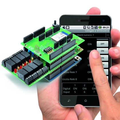
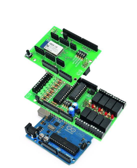
Today we’ll expand Arduino’s digital resources thanks to an I2C bus equipped shield and we’ll allow the management of the board via a bluetooth connection RN-42 through an Android systems.
All Arduino boards feature a number of digital I/Os. For the simplest projects, such resources are usually more than sufficient, but in those where they you need several control lines, “standard” I/Os can be less than enough, because some pins are shared with internal resources while others are dedicated to external shields.
In these cases, a possible solution is to switch to more powerful Arduinos (for example, the Mega, which has more I/Os than the classic Duemilanove or Uno) or use special expansion shield. In this article, we present one shield that allows you to add I/Os that can be handled very simply via an I²C bus data channel. The shield is basically what we call “I/O expander”. I²C bus management is provided by MCP23017 integrated circuit manufactured by Microchip.
The bus is made of three wires: one is the (common) ground while the other two are SCL (a clock that marks the communication) and SDA (Bi-directional serial data). In the I²C-Bus protocol the beginning of each communication session comes from a Master unit (Slaves can only reply to the Master), which sends 8 bytes commands, one of which contains the address of the Slave which is directed to. Since the address is made by one byte, the I²C-Bus could theoretically support 128 devices but you can only use 112, since 16 addresses are reserved. The identification of the individual slave units is usually done by setting the appropriate combination logic on the lines for which each integrated is provided: these lines are usually three allowing 8 combinations.
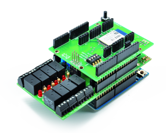
In our case, the ability to define the destination of the I²C-Bus commands allows us to connect several I²C I/O Expander board at the same time by stacking them one on top of the other. Each expansion board has 8 relay outputs and as many digital inputs, the I²C address of the MCP23017 chip can be selected from eight possible, so you can mount eight shield, until a total of 64 relay outputs and 64 digital inputs .
On top of this smart system we decided to add Bluetooth control, in order to manage it from a smartphone. To be super cool, we added our Bluetooth RN-42 shield, and we developed a special app for Android that allows you to view the status of all digital resources and send commands to activate outputs.
Being the overall system modular (you can add and remove Expander shields at will) it lends itself to different end-user applications. Both the Arduino firmware and the App will adapt: the firmware is indeed able to detect how many (and which) Expander shields are present while the App receives such information from Arduino and consequently adapt its own graphical user interface.
The App has a special configuration page that makes possible to set text labels to be used for the description of the I / O resources, thus adapting to your particular hardware configuration. Finally, there is a bluetooth setup page where you can set your name and pin code to be matched to the RN-42 shield.
Wiring Diagram of the I2C I/O Expander Shield

The circuit diagram of a single expansion shield has been developed around the U1 component, namely Microchip’s MCP23017. Find more info in the previous post.
Outputs end on U2, the ULN2803, specially designed to drive inductive loads such as relay coils (in fact, has several transistor stages with protection diodes of the base-collector junction).
Inputs (B port) are connected to appropriate circuit sections which carry the digital inputs. Each input has a protection diode, a pull-up resistor, and an LED that indicates the status. When the input is logically low (to ground) the corresponding LED is lit, and the I/O Expander shows that the input is “0”, whereas, when the input is high, the LED is off and the I/O Expander indicate that the input is “1”.
MCP23017 management happens though the I²C Bus protocol and by reading and writing specific registers. The SDA and SCL lines are available on pins 13 and 12, which, as you see in the wiring diagram, are taken to the corresponding pins of the Arduino board. As the MCP23017 has the ability to generate an interrupt when at least one pin programmed as input changes state, we used this function to handle inputs from the Arduino in interrupt mode instead of polling (thus being faster and without burdening the I²C bus). The interrupt allows you to initiate a connection, with the the Arduino operating as the Master unit. Clearly, as we’ll see later, the software must be specially crafted to take advantage of this feature.
Thanks to a jumper we left the possibility of bringing the MCP23017 interrupt pin (INTB, 19) as input on 2 different Arduino pins (D2 or D4) to fit as much as possible to the actual use.
MCP23017’s I2C address is selected via SW1 dip-switch: 3 dips are present therefore it is possible to connect up to 8 different shield without interfering with each of them.
Finally, there is a power supply section composed by the regulator U3 (integrated L78L05) which transforms the input voltage Vin to 5 volts needed to operate the entire circuit. Through the JP5V bridge you can choose to bypass the regulator but directly use the 5V supplied by the Arduino board.
The I2C I/O Expander Shield Arduino Library
We developed an ad hoc Arduino software library that provides all the routines needed for the detection of connected shields and I /O management.
The communication with the MCP23017 is based on the I2C Bus, so the library uses “Wire.h”. A function called “begin(int i2cAddress)” is available to initialize the single shield identified by an I2C address. Furthermore you have a “init()” to properly program the internal registers of the chip according to your needs and finally the “pinMode (int pin, int mode)” is to indicate whether the individual pins of I/O are inputs or outputs.
Besides the initialization functions, particularly interesting instructions are the “digitalRead (int pin)”, “digitalWrite (int pin, int val)”, “digitalWordRead ()” and “digitalWordWrite (word w)”, which respectively allow you to read the state of a single input pin, write a single output pin, read the status of all input pins (8 in our case), and finally write the status of all output pins (always 8).
As mentioned above, the management of the input is done via an interrupt, therefore this is a special function “pinDisableINT (int pin)” that allows you to set (or not to set) the pin as a single interrupt generator (in certain applications it may be useful to have the option not set all the input pins as interrupt generators but do it selectively)
The Arduino RN-42 Shield and library
The shield that makes the bluetooth connection possible is based on the Roving Networks RN-42, module. You can find the complete description of this module in a previous post here on this blog.
The Arduino firmware
Having previously defined the software library for the management of I/O Expander and Bluetooth shields, creating Arduino software is easier and straightforward.
Arduino’s CPU is responsible for managing both the I2C communication with the inputs and outputs (read/write logic state configuration) and the serial communication with the RN-42 (new connections or disconnections requests and data transmission protocol).
/****************************************************************************************************
* Titolo:       BluetoothIOControl                                                                  *
* Descrizione:  Software gestione shield I/O MCP23017 tramite shield Bluetooth RN-42                *
* Autori:       Ingg. Tommaso Giusto e Alessandro Giusto                                            *
* Data:         20/09/2013                                                                          *
                                                                   *
****************************************************************************************************/

/****************************************************************************************************
* Inclusione librerie                                                                               *
****************************************************************************************************/
#include <BluetoothRN42.h>
#include <Wire.h>
#include <IOExpanderMCP23017.h>
#include <EEPROM.h>

const int pinBoardLed = 13;
const int pinInterruptMCP23017 = 2;

/****************************************************************************************************
  0xFF,       // Byte ADD 000   Flag Reset EEPROM
                                  0x51 -> Non Eseguire Reset EEPROM
                                  Default -> Eseguire Reset EEPROM

  'B',        // Byte ADD 001   Nome Bluetooth del Sistema
  'T',        // Byte ADD 002   Default: 'BTIOControl' + 0xFF....
  'I',        // Byte ADD 003   Note: Max: 19 caratteri. Quelli non usati pari a 0xFF
  'O',        // Byte ADD 004
  'C',        // Byte ADD 005
  'o',        // Byte ADD 006
  'n',        // Byte ADD 007
  't',        // Byte ADD 008
  'r',        // Byte ADD 009
  'o',        // Byte ADD 00A
  'l',        // Byte ADD 00B
  0xFF,       // Byte ADD 00C
  0xFF,       // Byte ADD 00D
  0xFF,       // Byte ADD 00E
  0xFF,       // Byte ADD 00F
  0xFF,       // Byte ADD 010
  0xFF,       // Byte ADD 011
  0xFF,       // Byte ADD 012
  0xFF,       // Byte ADD 013

  '1',        // Byte ADD 014   PIN Code Bluetooth del Sistema
  '2',        // Byte ADD 015   Default: '1234' + 0xFF....
  '3',        // Byte ADD 016   Note: Max: 16 caratteri. Quelli non usati pari a 0xFF
  '4',        // Byte ADD 017
  0xFF,       // Byte ADD 018
  0xFF,       // Byte ADD 019
  0xFF,       // Byte ADD 01A
  0xFF,       // Byte ADD 01B
  0xFF,       // Byte ADD 01C
  0xFF,       // Byte ADD 01D
  0xFF,       // Byte ADD 01E
  0xFF,       // Byte ADD 01F
  0xFF,       // Byte ADD 020
  0xFF,       // Byte ADD 021
  0xFF,       // Byte ADD 022
  0xFF        // Byte ADD 023
****************************************************************************************************/
#define Flag_Reset_EEPROM_EEPROMADD         0x0000  // Flag Reset EEPROM

#define Start_Nome_Sistema_EEPROMADD        0x0001  // Struttura Nome Bluetooth del Sistema
#define Dimension_Nome_Sistema_EEPROM       19      // Byte struttura Nome Bluetooth del Sistema

#define Start_PIN_Code_Sistema_EEPROMADD    0x0014  // Struttura PIN Code Bluetooth del Sistema
#define Dimension_PIN_Code_Sistema_EEPROM   16      // Byte struttura PIN Code Bluetooth del Sistema

#define WLCOME_CMD      0x40

#define GETNFO_CMD      0x41

#define SETNFO_CMD      0x42

#define OKSTNF_CMD      0x43

#define ERSTNF_CMD      0x44

#define ERGTNF_CMD      0x45

#define STATUS_CMD      0x40

#define OUTRLE_CMD      0x41

#define INPDIG_CMD      0x42

#define NMEBTH_CMD      0x43

#define PNCBTH_CMD      0x44


#define INPUT1_PIN 0
#define INPUT2_PIN 1
#define INPUT3_PIN 2
#define INPUT4_PIN 3
#define INPUT5_PIN 4
#define INPUT6_PIN 5
#define INPUT7_PIN 6
#define INPUT8_PIN 7

#define OUTPUT1_PIN 15
#define OUTPUT2_PIN 14
#define OUTPUT3_PIN 13
#define OUTPUT4_PIN 12
#define OUTPUT5_PIN 11
#define OUTPUT6_PIN 10
#define OUTPUT7_PIN 9
#define OUTPUT8_PIN 8

#define Num_Max_Byte_Buffer_Bluetooth           35

BLUETOOTHRN42 bluetooth;

IOExpanderMCP23017 IOExpander[8];

char IOExpanderRilevati = 0x00;

char Stato_Uscite_Rele[8];
char Stato_Ingressi_Digitali[8];

void setup() {
  char i;

  memset(Stato_Ingressi_Digitali, 0x00, sizeof(Stato_Ingressi_Digitali));
  memset(Stato_Uscite_Rele, 0x00, sizeof(Stato_Uscite_Rele));

  pinMode(pinBoardLed, OUTPUT);
  digitalWrite(pinBoardLed, LOW);
  pinMode(pinInterruptMCP23017, INPUT);
  delay(1500);

  if (EEPROM.read(Flag_Reset_EEPROM_EEPROMADD) != 0x51) {
      EEPROM.write(Start_Nome_Sistema_EEPROMADD, 'B');
      EEPROM.write(Start_Nome_Sistema_EEPROMADD + 1, 'T');
      EEPROM.write(Start_Nome_Sistema_EEPROMADD + 2, 'I');
      EEPROM.write(Start_Nome_Sistema_EEPROMADD + 3, 'O');
      EEPROM.write(Start_Nome_Sistema_EEPROMADD + 4, 'C');
      EEPROM.write(Start_Nome_Sistema_EEPROMADD + 5, 'o');
      EEPROM.write(Start_Nome_Sistema_EEPROMADD + 6, 'n');
      EEPROM.write(Start_Nome_Sistema_EEPROMADD + 7, 't');
      EEPROM.write(Start_Nome_Sistema_EEPROMADD + 8, 'r');
      EEPROM.write(Start_Nome_Sistema_EEPROMADD + 9, 'o');
      EEPROM.write(Start_Nome_Sistema_EEPROMADD + 10, 'l');
      EEPROM.write(Start_Nome_Sistema_EEPROMADD + 11, 0xFF);
      EEPROM.write(Start_Nome_Sistema_EEPROMADD + 12, 0xFF);
      EEPROM.write(Start_Nome_Sistema_EEPROMADD + 13, 0xFF);
      EEPROM.write(Start_Nome_Sistema_EEPROMADD + 14, 0xFF);
      EEPROM.write(Start_Nome_Sistema_EEPROMADD + 15, 0xFF);
      EEPROM.write(Start_Nome_Sistema_EEPROMADD + 16, 0xFF);
      EEPROM.write(Start_Nome_Sistema_EEPROMADD + 17, 0xFF);
      EEPROM.write(Start_Nome_Sistema_EEPROMADD + 18, 0xFF);
      // PIN Code Bluetooth del Sistema
      EEPROM.write(Start_PIN_Code_Sistema_EEPROMADD, '1');
      EEPROM.write(Start_PIN_Code_Sistema_EEPROMADD + 1, '2');
      EEPROM.write(Start_PIN_Code_Sistema_EEPROMADD + 2, '3');
      EEPROM.write(Start_PIN_Code_Sistema_EEPROMADD + 3, '4');
      EEPROM.write(Start_PIN_Code_Sistema_EEPROMADD + 4, 0xFF);
      EEPROM.write(Start_PIN_Code_Sistema_EEPROMADD + 5, 0xFF);
      EEPROM.write(Start_PIN_Code_Sistema_EEPROMADD + 6, 0xFF);
      EEPROM.write(Start_PIN_Code_Sistema_EEPROMADD + 7, 0xFF);
      EEPROM.write(Start_PIN_Code_Sistema_EEPROMADD + 8, 0xFF);
      EEPROM.write(Start_PIN_Code_Sistema_EEPROMADD + 9, 0xFF);
      EEPROM.write(Start_PIN_Code_Sistema_EEPROMADD + 10, 0xFF);
      EEPROM.write(Start_PIN_Code_Sistema_EEPROMADD + 11, 0xFF);
      EEPROM.write(Start_PIN_Code_Sistema_EEPROMADD + 12, 0xFF);
      EEPROM.write(Start_PIN_Code_Sistema_EEPROMADD + 13, 0xFF);
      EEPROM.write(Start_PIN_Code_Sistema_EEPROMADD + 14, 0xFF);
      EEPROM.write(Start_PIN_Code_Sistema_EEPROMADD + 15, 0xFF);
      // Flag Reset EEPROM
      EEPROM.write(Flag_Reset_EEPROM_EEPROMADD, 0x51);
  }    // Se eseguire reset EEPROM

  // Avvio librerie Wire
  Wire.begin();

  // Avvio/rilevo libreria MCP23017
  IOExpanderRilevati = 0x00;
  for (i = 0; i < 8; i++) {
    // Avvio libreria MCP23017
    IOExpander[i].begin(i);

    // Se rilevo MCP23017
    if (IOExpander[i].init() == true) {
      // Setto flag IO Expander rilevato
      setIOExpanderRilevato(i);
      // Inizializzo modalità pin I/O MCP23017
      IOExpander[i].pinMode(INPUT1_PIN,  INPUT);
      IOExpander[i].pinMode(INPUT2_PIN,  INPUT);
      IOExpander[i].pinMode(INPUT3_PIN,  INPUT);
      IOExpander[i].pinMode(INPUT4_PIN,  INPUT);
      IOExpander[i].pinMode(INPUT5_PIN,  INPUT);
      IOExpander[i].pinMode(INPUT6_PIN,  INPUT);
      IOExpander[i].pinMode(INPUT7_PIN,  INPUT);
      IOExpander[i].pinMode(INPUT8_PIN,  INPUT);
      IOExpander[i].pinMode(OUTPUT1_PIN,  OUTPUT);
      IOExpander[i].pinMode(OUTPUT2_PIN,  OUTPUT);
      IOExpander[i].pinMode(OUTPUT3_PIN,  OUTPUT);
      IOExpander[i].pinMode(OUTPUT4_PIN,  OUTPUT);
      IOExpander[i].pinMode(OUTPUT5_PIN,  OUTPUT);
      IOExpander[i].pinMode(OUTPUT6_PIN,  OUTPUT);
      IOExpander[i].pinMode(OUTPUT7_PIN,  OUTPUT);
      IOExpander[i].pinMode(OUTPUT8_PIN,  OUTPUT);

      // Inizializzo interrupt pin input MCP23017
      IOExpander[i].pinEnableINT(INPUT1_PIN);
      IOExpander[i].pinEnableINT(INPUT2_PIN);
      IOExpander[i].pinEnableINT(INPUT3_PIN);
      IOExpander[i].pinEnableINT(INPUT4_PIN);
      IOExpander[i].pinEnableINT(INPUT5_PIN);
      IOExpander[i].pinEnableINT(INPUT6_PIN);
      IOExpander[i].pinEnableINT(INPUT7_PIN);
      IOExpander[i].pinEnableINT(INPUT8_PIN);
    }    // Chiusura if rilevo MCP23017
  }    // Chiusura ciclo for avvio/rilevo libreria MCP23017
}    // Chiusura funzione setup

// Programma Principale
void loop() {
  // Variabili buffer bluetooth inRX/TX
  char Buffer_Bluetooth_RX[Num_Max_Byte_Buffer_Bluetooth];
  char Buffer_Bluetooth_TX[Num_Max_Byte_Buffer_Bluetooth];
  // Flag connessione bluetooth attiva
  bool ConnessioneAttiva = false;
  // Flag eseguire config bluetooth
  bool EseguireConfigBluetooth = true;
  int Num_Byte;
  int timeOut;
  int i, j;

  // Ciclo infinito di esecuzione
  for (;;) {
    // Se rilevato interrupt input shield MCP23017
    if (digitalRead(pinInterruptMCP23017) == 0) {
      // Considero IO Expander rilevati
      for (j = 0; j < 8; j++) {
        // Se IO Expander rilevato
        if (IOExpanderRilevato(j) == true) {
          // Azzero stato ingressi digitali
          Stato_Ingressi_Digitali[j] = 0x00;
          // Leggo stato ingressi digitali
          for (i = 0; i < 8; i++) {
            if (IOExpander[j].digitalRead(INPUT1_PIN + i) == HIGH)
              Stato_Ingressi_Digitali[j] |= (1 << i);
          }
        }    // Chiusura if IO Expander rilevato
      }    // Chiusura ciclo for considero IO Expander rilevati
    }    // Chiusura if rilevato interrupt input shield MCP23017

    // Se nessuna connessione attiva
    if (ConnessioneAttiva == false) {
      // Se eseguire config bluetooth
      if (EseguireConfigBluetooth == true) {
        // Configurazione bluetooth RN-42
        configBluetooth();
        // Reset flag reset modulo
        EseguireConfigBluetooth = false;
      }    // Chiusura if eseguire config bluetooth

      // Se ricevuti byte dal modulo
      if (bluetooth.Available_RN_42() != 0) {
        // Se richiesta nuova connessione
        if (bluetooth.New_Connection_Request_RN_42() == true) {
          // Attivo led segnalazione
          digitalWrite(pinBoardLed, HIGH);
          // Invio risposta richiesta connessione: WLCOME
          Buffer_Bluetooth_TX[0] = WLCOME_CMD;
          bluetooth.Write_Buffer_Bluetooth_RN_42(Buffer_Bluetooth_TX, Num_Max_Byte_Buffer_Bluetooth);

          // Avvio scansione time out
          timeOut = 0;

          // Indico connessione collegata
          ConnessioneAttiva = true;
        }     // Chiusura if richiesta nuova connessione
      }     // Chiusura if ricevuti byte dal modulo
    }    // Chiusura if nessuna connessione attiva
    // Se connessione attiva
    else {
      // Se ricevuti byte dal modulo
      if (bluetooth.Available_RN_42() != 0) {
        // Se rilevata disconnessione
        if (bluetooth.Close_Connection_Request_RN_42() == true) {
          // Disattivo led segnalazione
          digitalWrite(pinBoardLed, LOW);
          // Indico connessione non collegata
          ConnessioneAttiva = false;
        }     // Chiusura if rilevata disconnessione

        // Se non rilevata disconnessione
        else {
          // Leggo i byte dal buffer di ricezione
          Num_Byte = bluetooth.Read_Buffer_Bluetooth_RN_42(Buffer_Bluetooth_RX);
          // Seleziono codice comando ricevuto
          switch (Buffer_Bluetooth_RX[0]) {
            // Se ricevuto comando richiesta lettura dati (GET)
            case GETNFO_CMD:
              // Seleziono identificativo risorsa
              switch (Buffer_Bluetooth_RX[1]) {
                // Se ricevuto identificativo pagina stato scheda (GET STATUS)
                case STATUS_CMD:
                  // Invio Stato shield IO Expander rilevati
                  Buffer_Bluetooth_TX[0] = IOExpanderRilevati;
                  // Invio Stato uscite rele/ingressi digitali IO Expander
                  for (j = 0; j < 8; j++) {
                    // Se IO Expander selezionato non rilevato
                    if (IOExpanderRilevato(j) == false) {
                      // Azzero stato I/O Expander
                      Stato_Uscite_Rele[j] = 0x00;
                      Stato_Ingressi_Digitali[j] = 0x00;
                    }

                    // Invio stato I/O Expander
                    Buffer_Bluetooth_TX[1 + (j * 2)] = Stato_Uscite_Rele[j];
                    Buffer_Bluetooth_TX[2 + (j * 2)] = Stato_Ingressi_Digitali[j];
                  }
                  bluetooth.Write_Buffer_Bluetooth_RN_42(Buffer_Bluetooth_TX, Num_Max_Byte_Buffer_Bluetooth);
                  break;      // Chiusura case ricevuto identificativo pagina stato scheda (GET STATUS)

                // Se ricevuto identificativo uscite rele (GET OUTRLE_CMD)
                case OUTRLE_CMD:
                  // Se IO Expander selezionato rilevato
                  if (IOExpanderRilevato(Buffer_Bluetooth_RX[2]) == true)
                    // Invio stato uscita rele selezionata
                    Buffer_Bluetooth_TX[0] = Stato_Uscite_Rele[Buffer_Bluetooth_RX[2]];
                  // Se IO Expander selezionato non rilevato
                  else
                    // Invio risposta negativa comando GETNFO: (ERGTNF)
                    Buffer_Bluetooth_TX[0] = ERGTNF_CMD;

                  bluetooth.Write_Buffer_Bluetooth_RN_42(Buffer_Bluetooth_TX, Num_Max_Byte_Buffer_Bluetooth);
                  break;      // Chiusura case ricevuto identificativo uscite rele (GET OUTRLE_CMD)

                // Se ricevuto identificativo ingressi digitali (GET INPDIG)
                case INPDIG_CMD:
                  // Se IO Expander selezionato rilevato
                  if (IOExpanderRilevato(Buffer_Bluetooth_RX[2]) == true)
                    // Invio stato ingresso digitale selezionato
                    Buffer_Bluetooth_TX[0] = Stato_Ingressi_Digitali[Buffer_Bluetooth_RX[2]];
                  // Se IO Expander selezionato non rilevato
                  else
                    // Invio risposta negativa comando GETNFO: (ERGTNF)
                    Buffer_Bluetooth_TX[0] = ERGTNF_CMD;

                  bluetooth.Write_Buffer_Bluetooth_RN_42(Buffer_Bluetooth_TX, Num_Max_Byte_Buffer_Bluetooth);
                  break;      // Chiusura case ricevuto identificativo ingressi digitali (GET INPDIG)
              }     // Chiusura switch seleziono identificativo risorsa
              break;      // Chiusura case ricevuto comando richiesta lettura dati (GET)

              // Se ricevuto comando richiesta scrittura dati (SET)
              case SETNFO_CMD:
                // Seleziono identificativo risorsa
                switch (Buffer_Bluetooth_RX[1]) {
                  // Se ricevuto identificativo uscite rele (SET OUTRLE_CMD)
                  case OUTRLE_CMD:
                    // Se ricevuti parametri corretti
                    if ((Buffer_Bluetooth_RX[2] >= 0) && (Buffer_Bluetooth_RX[2] <= 7) &&
                        (Buffer_Bluetooth_RX[3] >= 0) && (Buffer_Bluetooth_RX[3] <= 7) &&
                        (Buffer_Bluetooth_RX[4] >= 0) && (Buffer_Bluetooth_RX[4] <= 1)) {
                      // Imposto stato uscita rele
                      IOExpander[Buffer_Bluetooth_RX[2]].digitalWrite(OUTPUT1_PIN - (int) (Buffer_Bluetooth_RX[3]), (int) (Buffer_Bluetooth_RX[4]));
                      // Memorizzo stato uscita rele attuale
                      if (Buffer_Bluetooth_RX[4] == 0)
                        Stato_Uscite_Rele[Buffer_Bluetooth_RX[2]] &= (~(1 << Buffer_Bluetooth_RX[3]));
                      else if (Buffer_Bluetooth_RX[4] == 1)
                        Stato_Uscite_Rele[Buffer_Bluetooth_RX[2]] |= (1 << Buffer_Bluetooth_RX[3]);

                      // Invio risposta positiva comando SETNFO: (OKSTNF)
                      Buffer_Bluetooth_TX[0] = OKSTNF_CMD;
                    }    // Chiusura if ricevuti parametri corretti
                    // Se ricevuti parametri errati
                    else
                      // Invio risposta negativa comando SETNFO: (ERSTNF)
                      Buffer_Bluetooth_TX[0] = ERSTNF_CMD;

                    bluetooth.Write_Buffer_Bluetooth_RN_42(Buffer_Bluetooth_TX, Num_Max_Byte_Buffer_Bluetooth);
                    break;    // Chiusura case ricevuto identificativo uscite rele (SET OUTRLE_CMD)

                  // Se ricevuto identificativo nome bluetooth del sistema (SET NMEBTH_CMD)
                  case NMEBTH_CMD:
                    // Memorizzo in EEPROM carattere nome ricevuto
                    EEPROM.write(Start_Nome_Sistema_EEPROMADD + Buffer_Bluetooth_RX[2], Buffer_Bluetooth_RX[3]);

                    // Se ricevuto ultimo carattere nome
                    if (Buffer_Bluetooth_RX[2] == (Dimension_Nome_Sistema_EEPROM - 1))
                      // Set flag reset modulo
                      EseguireConfigBluetooth = true;

                    // Invio risposta positiva comando SETNFO: (OKSTNF)
                    Buffer_Bluetooth_TX[0] = OKSTNF_CMD;
                    bluetooth.Write_Buffer_Bluetooth_RN_42(Buffer_Bluetooth_TX, Num_Max_Byte_Buffer_Bluetooth);
                    break;      // Chiusura case ricevuto identificativo nome bluetooth del sistema (SET NMEBTH_CMD)

                  // Se ricevuto identificativo pin code bluetooth del sistema (SET PNCBTH_CMD)
                  case PNCBTH_CMD:
                    // Memorizzo in EEPROM carattere PIN code ricevuto
                    EEPROM.write(Start_PIN_Code_Sistema_EEPROMADD + Buffer_Bluetooth_RX[2], Buffer_Bluetooth_RX[3]);

                    // Se ricevuto ultimo carattere PIN code
                    if (Buffer_Bluetooth_RX[2] == (Dimension_PIN_Code_Sistema_EEPROM - 1))
                      // Set flag reset modulo
                      EseguireConfigBluetooth = true;

                    // Invio risposta positiva comando SETNFO: (OKSTNF)
                    Buffer_Bluetooth_TX[0] = OKSTNF_CMD;
                    bluetooth.Write_Buffer_Bluetooth_RN_42(Buffer_Bluetooth_TX, Num_Max_Byte_Buffer_Bluetooth);
                    break;      // Chiusura case ricevuto identificativo pin code bluetooth del sistema (SET PNCBTH_CMD)

                 // Se ricevuto identificativo errato
                 default:
                   // Invio risposta negativa comando SETNFO: (ERSTNF)
                   Buffer_Bluetooth_TX[0] = ERSTNF_CMD;
                   bluetooth.Write_Buffer_Bluetooth_RN_42(Buffer_Bluetooth_TX, Num_Max_Byte_Buffer_Bluetooth);
                   break;      // Chiusura case ricevuto identificativo errato
               }     // Chiusura switch seleziono identificativo risorsa
               break;      // Chiusura case ricevuto comando richiesta scrittura dati (GET)
          }     // Chiusura switch seleziono codice comando ricevuto
        }    // Chiusura else non rilevata disconnessione

        // Resetto scansione time out
        timeOut = 0;
      }     // Chiusura if ricevuti byte dal modulo

      // Se non ricevuti byte dal modulo
      else {
        // Attesa time out
        delay(250);
        // Incremento timeout connessione
        timeOut++;
        // Se time out connessione scaduto
        if ((timeOut * 250) >= 5000) {
          // Chiudo connessione attuale modulo RN-42 (reboot)
          bluetooth.Kill_Connection_RN_42();
          // Segnalo disconnessione
          for (i = 0; i < 10; i++) {
            digitalWrite(pinBoardLed, HIGH);
            delay(50);
            digitalWrite(pinBoardLed, LOW);
            delay(50);
          }    // Segnalo disconnessione

          // Indico connessione non collegata
          ConnessioneAttiva = false;
        }     // Chiusura if time out connessione scaduto
      }     //  Chiusura else non ricevuti byte dal modulo
    }    // Chiusura else connessione attiva
  }    // Ciclo infinito di esecuzione
}    // Chiusura funzione loop

// Configurazione bluetooth RN-42
void configBluetooth() {
  String Nome = "";
  String PIN = "";
  char NomePINChar;

  // Begin software for bluetooth
  bluetooth.Begin();
  // Enter in command mode
  bluetooth.Enter_Command_Mode_RN_42();
  // Set factory default
  bluetooth.Set_Factory_Default_RN_42();
  // Set bluetooth operation mode as slave (0)
  bluetooth.Set_Operation_Mode_Slave_RN_42();
  // Set Extended Status String RN-42 module
  bluetooth.Set_Extended_Status_String_RN_42();
  // Set config timer RN-42 module
  bluetooth.Set_Config_Timer_RN_42();
  // Set Inquiry Scan Window RN-42 module
  bluetooth.Set_Inquiry_Scan_Window_RN_42();
  // Set Page Scan Window RN-42 module
  bluetooth.Set_Page_Scan_Window_RN_42();

  // Leggo i caratteri nome bluetooth
  for (int tmp = 0; tmp < Dimension_Nome_Sistema_EEPROM; tmp++) {
    // Leggo singolo carattere
    NomePINChar = EEPROM.read(Start_Nome_Sistema_EEPROMADD + tmp);
    // Se trovato carattere fine nome
    if (NomePINChar == (char) (0xFF))
      // Blocco ciclo for leggo i caratteri nome bluetooth
      break;

    // Accodo carattere letto
    Nome = Nome + NomePINChar;
  }
  // Set name of bluetooth
  bluetooth.Set_Name_RN_42(Nome);

  // Leggo i caratteri PIN bluetooth
  for (int tmp = 0; tmp < Dimension_PIN_Code_Sistema_EEPROM; tmp++) {
    // Leggo singolo carattere
    NomePINChar = EEPROM.read(Start_PIN_Code_Sistema_EEPROMADD + tmp);
    // Se trovato carattere fine PIN
    if (NomePINChar == (char) (0xFF))
      // Blocco ciclo for leggo i caratteri PIN bluetooth
      break;

    // Accodo carattere letto
    PIN = PIN + NomePINChar;
  }
  // Set PIN of bluetooth
  bluetooth.Set_PIN_Code_RN_42(PIN);

  // Enter in data mode
  bluetooth.Enter_Data_Mode_RN_42();
  // Reboot RN-42 module
  bluetooth.Reboot_RN_42();
}    // Chiusura funzione configBluetooth

// Verifica se un IO Expander è stato rilevato
boolean IOExpanderRilevato(int ExpanderNum) {
  // Se IO Expander selezionato non rilevato
  if ((IOExpanderRilevati & (1 << ExpanderNum)) == 0x00)
    return(false);
  // Se IO Expander selezionato rilevato
  else
    return(true);
}    // Chiusura funzione IOExpanderRilevato

// Setta flag IO Expander è stato rilevato
void setIOExpanderRilevato(int ExpanderNum) {
  // Setto flag IO Expander rilevato
  IOExpanderRilevati |= (1 << ExpanderNum);
}    // Chiusura funzione setIOExpanderRilevato

// Resetta flag IO Expander è stato rilevato
void resetIOExpanderRilevato(int ExpanderNum) {
  // Resetto flag IO Expander rilevato
  IOExpanderRilevati &= (~(1 << ExpanderNum));
}    // Chiusura funzione resetIOExpanderRilevato
The Android Software
The Software developed for Android smartphones (“ShieldIOControl”) allows you to connect and remotely manage the system: you can check the current status of all digital inputs, realize the state of the outputs (ON or OFF) and change the value to suit your needs. The display of different measured shield is managed by pages and you can “browse” through the different pages thanks to two buttons.
Graphical labels that identify the various I/O and their status descriptions can be configured by software and saved so that they are restored to the subsequent executions. We point out, however, that these settings are stored in the smartphone and not in the PCB (it would take too many bytes of EEPROM), so if you use 2 or more smartphones for the management of electronics, you must run the configuration on both ends.
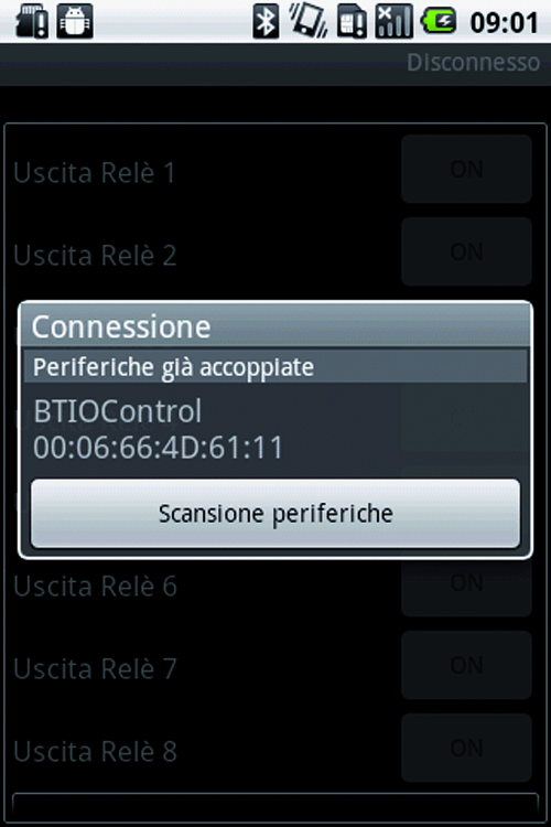
At start-up, after an initial presentation screen, the app starts scanning and detecting all bluetooth devices present within the coverage area. In the list that appears all systems already paired and the new detected are shown. By clicking on the single board label (“BTIOControl” in our example), you select it and require to start the connection. A button to request a new execution of the scan and update the list s also available.
At this point if it is the first time that the device is detected, you are asked to enter the PIN code (“1234” by default; Screenshot_2_Articolo image). Later you switch to the main screen of the program: starting from the top you see the number of shield shown, the status of the 8 relay outputs and 8 digital inputs. Next to the label that identifies the shield are two buttons to switch to the previous and next shield.
For each output the following convention is used: on the extreme left is the text label that identifies the resource, then it is indicates the current status (always via text label) and then right-most button can be used to change the current status. Whether the output is on or off the text label is updated (ON or OFF in our example) and the button is enabled.

For each digital input is instead present only a single text label showing the current status: ON in our example in the case in which the digital input is high; OFF otherwise.
Coming back to outputs, to request the change of the current state you simply click on the appropriate button: at this point the selected command is sent to the card and, upon completion, the graphical user interface is updated.
During normal operation, a refresh timer helps the app to cyclically connect to the board, read the current status and update the graphical interface of all the shields.

By choosing Android’s “menu” button, the configuration menu pops up consisting of two buttons: “BT Config” allows to select the configuration of the bluetooth boad and “Text Config” allows to configure the text labels.
In the first configuration page there are 2 configuration sections “System Name” and “PIN code”: each section has a text field to edit and a button to confirm the configuration.
On the second configuration page, you can setup eight text labels, descriptive of each output; two more to identify the state of the outputs, and finally an additional two labels are matched to the two-state inputs. On the right, a button helps reset al the default configurations, while on the left a “OK” button confirms the entered values.
Mounting on the Arduino Uno
In case you want to implement the project presented today using an Arduino Uno (the simplest but also the more widespread version) we highlight that Arduino Uno early versions used the A4 and A5 pins for the I2C bus (SDA and SCL signal). Starting from Rev. 3 2 pins have been added just for the communication channel but the designers also left, however, pins A4 and A5 connected to the bus.
As we saw in the post Arduino’s CPU communicates with the I/O Expander shield by using the I2C bus while the RN-42 module of the bluetooth shield has some GPIO; 3 of these are brought towards Arduino (in particular the GPIO9 refers to pin A4).
We can easily understand that this would generate an incompatibility on pin A4 (which would be connected to both the I2C bus to the MCP23017 and the GPIO9 of the RN-42): this problem would affects the proper functioning of the board, indeed, at the startup of the same, the I2C bus would be blocked and therefore the software would not run correctly.
The solution to this problem is, when stacking the shields, to add the Bluetooth shield as the last on (above all also to avoid communication interference), and, on this shield, leaving the pin that corresponds to Arduino A4 floating (meaning not plugged into the corresponding female strip; refer to the mounting plane for an image that is explanatory of the final result you should aim for).
In this way the Arduino One is able to communicate with the MCP23017 via I2C bus and with the bluetooth RN-42 via the serial port (clearly the GPIO9 may not be used or, at least, connected with Arduino).
In the store
I/O expander shield for Arduino

You may need $11.9 Arduino shield CANBUS here: http://www.elecfreaks.com/store/canbus-shield-p-746.html